

Page 1
USER
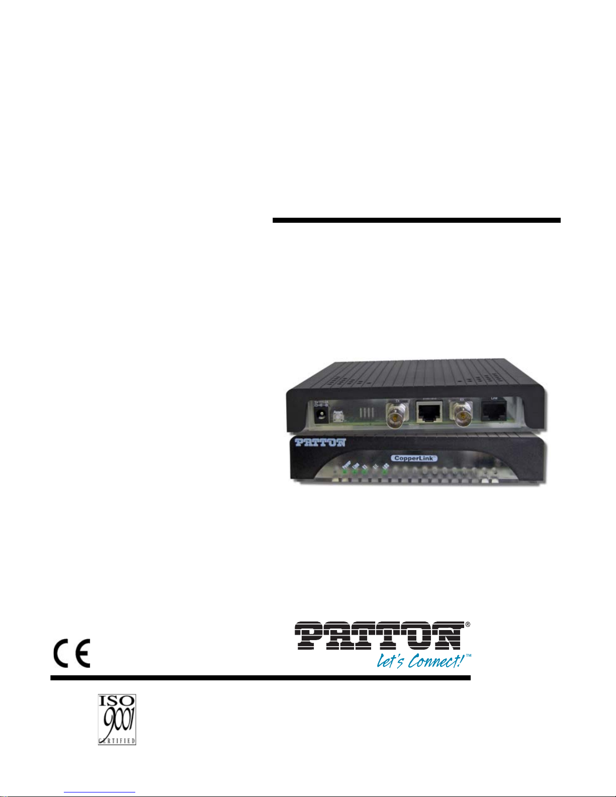
MANUAL
MODEL 2113A
CopperLINK™ E1 Extender
REGULATORY MODEL NUMBER:
03340D4-001
This is a Class A device and is not intended for
use in a residential environment.
Part# 07M2113A-UM
Rev . A
Revised 2/2/12
An ISO-9001Certified
Company
SALES OFFICE
(301) 975-1000
TECHNICAL SUPPORT
(301) 975-1007
Page 2

CONTENTS
1.0 Warranty Information ................................................................. 3
1.1 Regulatory Information ................................................................. 3
EMC Directive:......................... ...... ............................ ...... ..... ...... .. 3
Low-Voltage Direcive (Safety):..................................................... 3
1.2 Radio and TV Interference (FCC Part 15).................................... 4
1.3 CE Declaration of Conformity....................................................... 4
1.4 Authorized European Representative........................................... 4
1.5 Service.......................................................................................... 4
1.6 Safety When Working With Electricity .......................................... 5
2.0 General Information.................................................................... 7
2.1 Features........................................................................................ 7
2.2 Description.................................................................................... 7
3.0 Installation................................................................................... 8
3.1 Connecting the Line Port.............................................................. 9
3.2 Connecting the E1 In terface ....................................................... 10
3.3 Connecting Power ......................... ............................................. 10
4.0 Operation................................................................................... 11
4.1 Front Panel LED Status Monitors............................................... 11
4.2 Configuration and Dip Switches.................................................. 12
Switch S4-1: Line Build Out........................................................ 12
A
Specifications ........................................................................... 13
A.1 Circuit Rate ................................................................................. 13
A.2 Circuit Interface .......................................................................... 13
A.3 Circuit Defaults ........................................................................... 13
A.4 Circuit Connector ........................................................................ 13
A.5 LED Status Indicators ................................................................. 13
A.6 Transmission Line ....................................................................... 13
A.7 Line Coding ................................................................................ 13
A.8 Line Interface .............................................................................. 13
A.9 Line Physical Connection ........................................................... 13
A.10 Power Supply .............................................................................. 13
A.11 Environmental ............................................................................. 13
A.12 Dimensions ................................................................................. 13
B
Model 2113A Series Factory
Replacement Parts and Accessories...................................... 14
2
Page 3

1.0 WARRANTY INFORMATION
Patton Electronics warrants all Model 2113A components to be free
from defects, and will—at our option—repair or replace the product
should it fail within one year from the first date of the shipment.
This warranty is l im ite d to defe cts in workmanship or materials, a nd doe s
not cover customer damage, abuse or unauthorized modification. If this
product fails or does not performs as warranted, your sole recourse shall
be repair or replacement as described above. Under no condition shall
Patton Electronics be liable for an y damage s incurr ed by the use of thi s
product. The se dama ges i nclud e, b ut are n ot lim ited to, t he fol lowing: lost
profits, lost savings and incidental or consequential damages arising
from the use of or inability to use this product. Patton Electronics spe
cifically disclaims all other warranties, expressed or implied, and the
installation or use of this product shall be deemed an acceptance of
these terms by the user.
Note Conformity documents of all Patton products can be viewed
online at www.patton.com under the appropriate product page.
1.1 REGULATORY INFORMATION
EMC Directive:
• FCC Part 15, Class A
• EN55022, Class A
• EN55024
Low-Voltage Direcive (Safety):
• UL 60950-1/CSA 22.22 NO. 60950-1
• IEC/EN60950-1, 2nd Edition
• AS/NZS 60950-1
3
Page 4

1.2 RADIO AND TV INTERFERENCE (FCC PART 15)
This device generates and uses radio frequency energy, and if not
installed and use d proper ly- that is, in s trict ac corda nce with the man ufac
turer’s instructions-may cause interference to radio and television reception. The dev ic e h as b een tested and found to comply w i th t he limits for a
Class A computin g dev ice in ac c orda nc e w ith spec ifications in Subpart B
of Part 15 of FCC rules, which are designed to provide reasonable protection from such interference in a commercial installation. However,
there is no gua ran tee that interference will not occur in a particular instal
lation. If the device does cause interference to radio or television reception, which can be determined by disconnecting the unit, the user is
encouraged to try to corr ect the interf erence by on e or more of t he follow
ing measures: moving the computing equipment away from the receiver,
re-orienting the receiving antenna and/or plugging the receiving equip
ment into a different AC outlet (such that the computing equipment and
receiver are on different branches).
1.3 CE DECLARATION OF CONFORMITY
Patton Electronics, Inc declares that this device is in compliance with the
essential requirements and other relevant provisions of Directive
2004/108/EC relating to electromagnetic compatibility and Directive
2006/95/EC relating to electrical equipment designed for use within cer
tain voltage limits. The Declaration of Conformity may be obtained from
Patton Electronics, Inc at w ww.patton.com/certifications.
The safety advice in the documentation accompanying this device shall
be obeyed. The conformity to the above directive is indicated by CE
mark on the device.
1.4 AUTHORIZED EUROPEAN REPRESENTATIVE
D R M Green, European Compliance Services Limited.
Avalon House, Marcham Road, Abingdon, Oxon OX14 1UD, UK
1.5 SERVICE
All warranty and non-warranty repairs must be returned freight prepaid
and insured to Patto n Elec tro nic s. All retu rns must hav e a R et urn Mate ri
als Authorization number on the outside of the shipping container. This
number may be obtained from Patton Electronics Technical Services at:
•Tel: +1 (301) 975-1007
•Email: support@patton.com
• URL: http://www.patton.com
4
Page 5

1.6 SAFETY WHEN WORKING WITH ELECTRICITY
• This device contains no user serviceable parts. This
device can only be repaired by qualified service per
sonnel.
• Do not open the device when the power cord is connected. For systems without a power switch and without
an external power adapter, line voltages are present
within the device when the power cord is connected.
• For devices with an external power adapter, the power
adapter shall be a listed Limited Power Source. The
mains outlet that is utilized to power the device shall be
within 10 feet (3 meters) of the device, shall be easily
accessible, and protected by a circuit breaker in com
pliance with local regulatory requirements.
• For AC powered devices, ensure that the power cable
used meets all applicable standards for the country in
which it is to be installed.
-
-
WARNING
• For AC powered devices which have 3 conductor
power plugs (L1, L2 & GND or Hot, Neutral &
Safety/Protective Ground), the wall outlet (or socket)
must have an earth ground.
• For DC powered devices, ensure that the interconnecting cables are rated for proper voltage, current, anticipated temperature, flammability, and mechanical
serviceability.
• WAN, LAN & PSTN ports (connections) may have hazardous voltages present regardless of whether the
device is powered ON or OFF. PSTN relates to inter
faces such as telephone lines, FXS, FXO, DSL, xDSL,
T1, E1, ISDN, Voice, etc. These are known as “hazard
ous network voltages” and to avoid electric shock use
caution when working near these ports. When discon
necting cables for these ports, detach the far end connection first.
• Do not work on the device or connect or disconnect
cables during periods of lightning activity.
5
Page 6

WARNING
WARNING
In accordance with the requirements of council directive 2002/96/EC on Waste of Electrical and Electronic
Equipment (WEEE), ensure that at end-of-life you sepa
rate this product from other waste and scrap and deliver
to the WEEE collection system in your country for recy
cling.
This device contains no user serviceable parts. This
device can only be repaired by qualified service per
sonnel.
This device is NOT intended nor approved for connection to the PSTN. It is intended only for connection to
customer premise equipment.
-
-
-
WARNING
Electrostatic Discharge (ESD) can damage equipment
and impair electrical circuitry. It occurs when electronic
printed circuit cards are improperly handled and can
result in complete or intermittent failures. Do the fol
lowing to prevent ESD:
• Always follow ESD prevention procedures when
removing and replacing cards.
• Wear an ESD-preventive wrist strap, ensuring that it
makes good skin contact. Connect the clip to an
unpainted surface of the chassis frame to safely chan
nel unwanted ESD voltages to ground.
• To properly guard against ESD damage and shocks,
the wrist strap and cord must operate effectively. If no
wrist strap is available, ground yourself by touching the
metal part of the chassis.
-
-
6
Page 7

2.0 GENERAL INFORMATION
Thank you for your purchase of this Patton Electronics product. This
product has been thoroughly inspected and tested and is warranted for
one year for parts and labor. If any questions or problems arise during
installation or use of this product, contact Patton Electronics Technical
Support at +1 (301) 975-1007.
Note The 2113A includes software developed under third party
licenses. Contact Patton for more information.
2.1 FEATURES
• Easy-to-install E1 Extender—no configuration required
• Data rate set to 2.048 Mbps on an unframed E1
• Plug ‘n’ Play for easy installations
• LED indicators for Power, Ethernet Link, and Frame
• CE marked
2.2 DESCRIPTION
The Patton Electronics Model 2113A CopperLink provides high speed 2wire E1 extension connectivity to ISPs, P TTs, and enterprise environm ents
using binder group friendly TC-PAM modulation.
Line connection is made with an RJ-45 jack. The Model 2113A is powered
by an 100/230 VAC (Universal) supply. The E1 Extender features exter
nally-accessible DIP switches, loopback dia gnostics, and CopperLink Plug
‘n’ Play.
-
7
Page 8

3.0 INSTALLATION
The Interconnecting cables shall be acceptable for
external use and shall be rated for the proper application with respect to voltage, current, anticipated tem-
CAUTION
perature, flammability, and mechanical serviceability.
To install the 2113A E1 Extender, do the following:
1. Connect the line interface (ref er to sec tion 3.1 , “Con necting th e Line
Port” on page 9)
2. Connect the E1 interface (refer to section 3.2, “Connecting the E1
Interface” on page 10).
3. Co nnect the po wer plug (refer to section 3.3 , “Connecti ng Power” on
page 10).
RX (75 Ohm)
(Data from
G.703/G.704
Power
Figure 1. Model 2113A rear panel
network)
8
E1 interface
(120 Ohm)
Line
TX (75 Ohm)
(Data to
G.703/G.704
network)
Page 9

3.1 CONNECTING THE LINE PORT
The Interconnecting cables shall be acceptable for
external use and shall be rated for the proper applica
-
tion with respect to voltage, current, anticipated tem-
CAUTION
perature, flammability, and mechanical serviceability.
Follow the steps below to connect the Model 2113A CopperLINK Line
port.
Note The Model 2113A units work in pairs. One of the units must be
configured as a (L) Local unit, and the other unit must be configured as a (R) Remote unit.
To function properly, the two E1 Extenders must be connected together
using twisted-pair, unconditioned, dry, metal wire, between 19 (0.9mm)
and 26 AWG (0.4mm). Leased circuits that run through signal equaliza
-
tion equipment are not acceptable.
Follow the steps below to connect the CopperLink line port:
1. Obtain a single-twisted pair cable with an RJ-45 plug connector at
each end.
2. Plug one end of the cable into the RJ-45 socket (labeled Line) on
the CopperLink 2113A.
3. When the remote and local extender units synchronize, the frontpanel green Line LED will turn on.
The RJ-45 connector on the Model 2113A's twisted pair interface is
polarity insensitive and is wired for a two-wire interface. The signal/pin
relationship is shown in Figure 2.
1 (no connection)
1
2
3
4
5
6
7
8
2 (no connection)
3 (no connection)
4 (RING)
5 (TIP)
6 (no connection)
7 (no connection)
8 (no connection)
Figure 2. Model 2113A (RJ-45) twisted pair line interface.
9
Page 10

3.2 CONNECTING THE E1 INTERFACE
The Interconnecting cables shall be acceptable for
external use and shall be rated for the proper applica
-
tion with respect to voltage, current, anticipated tem-
CAUTION
perature, flammability, and mechanical serviceability.
Your CopperLink comes with an RJ-48C and dual BNC for connection to
E1.To connect the twisted pair cable to the CopperLink E1 port, attach
the male connec tor of the twist ed pair cable to the femal e R J-48 connec
tor on the CopperLink. Attach the other end of the cable to the RJ-48
connector on the local E1.
The Model 2113A is equipped with dual female BNCs (TX and RX) for
connection to a 75-ohm dual coax E1 network interface. To connect the
BNC connectors of the E1 interface on the Model 2113A, simply use a
coaxial cable with a BNC connector at each end to connect the pair of
Model 2113As.
3.3 CONNECTING POWER
The Interconnecting cables shall be acceptable for
external use and shall be rated for the proper applica
-
tion with respect to voltage, current, anticipated tem-
CAUTION
perature, flammability, and mechanical serviceability.
The Model 2113A does not have a power sw itch, so it powers up as soon
as it is plugged in.
An external AC or DC power supply is available separately. This connection is made via the barrel jack on the rear panel of the Model 2113A. No
configuration is necessary for the power supply (See Appendix B for
domestic and international power supply and cord options).
DC power (supplied via the power supply jack to the 2113A) must meet
the following requirements; DC power supplied must be regulated 5VDC
±5%, 1.0A minimum. Center pin is +5V. The barrel type plug has a
2.5/5.5/10mm I.D./O.D./Shaft Length dimensions.
10
Page 11

4.0 OPERATION
Once the Model 2113As are properly installed, they should operate
transparently. No user settings required. This section describes reading
the LED status monitors.
Before applying power to the Model 2113A, please review section 3.3,
“Connecting Power” on pa ge 10 to verify that the unit is connected to the
appropriate power sourc e.
4.1 FRONT PANEL LED STATUS MONITORS
The Model 2113A features five front panel LEDs that monitor power, the
line connection, the E1 connection, and any signal errors.
Loss of Signal
Error
E1 Connection
Power
Figure 3. Model 2113A front panel
Tab le 1: Front panel LED description
Link
LED Status Description
Power Green The device is powered on.
Off The device is powered of f.
Line Green The port is connected.
*
Blinking Green
Linking with the other unit in the pai r
Off No valid link on this port.
E1 Green The interface is connected.
Blinking Green Data transceiving.
Off No valid link on this port.
T/E Yellow Test mode in progress
Blinking Yellow Test mode is starting, or errors detected.
Off Test mode is off/No errors p resent
LOS Blinking Red Framing errors/clock slips det ected
Off No errors present
*.
Once the unit connects to a power source, the Line LED will
blink as the 2113A automatically looks for the other unit in the
pair.
11
Page 12

4.2 CONFIGURATION AND DIP SWITCHES
The CopperLink 2113A E1 Extender is Plug ‘n’ Play enabled and does
not require any configuration by the user.
Note The user should NOT change any of the dip switches except
for S4-1 (if necessary). If the user changes the position of any of
the dip switches (except for S4-1), it will affect the operation of
the unit.
ON
1 2 3 4 5 6 7 8
ON
ON
1 2 3 4 5 6 7 8
1 2 3 4 5 6 7 8
ON
ON
1 2 3 4 5 6 7 8
1 2 3 4 5 6 7 8
Model 2113A
ON
ON
S4
S3
S3
S1
S1
1 2 3 4 5 6 7 8
Figure 4. Model 2113A DIP Switch Location
Switch S4-1: Line Build Out
Switch S4-1 defines the shape of the waveform on the E1 line.
Tab le 2: S4-1 Default Position
Switch Position Setting
S4-1 ON 120-ohm
S4-1 OFF 75-ohm
OFF
12
Page 13

APPENDIX A
S PECIFICATIONS
A.1 CIRCUIT RATE
• Model 2113A - 2.048 Mbps
A.2 CIRCUIT INTERFACE
• G .703/G.704 interface. Either 75 Ohms (unbalanced) or 120 Ohms (bal-
anced). Pins 1 & 2 are Receive. Pins 4 & 5 are transmit.
A.3 CIRCUIT DEFAULTS
• E1 Line Cod ing = HDB 3.
A.4 CIRCUIT CONNECTOR
• Dual BNC and RJ48C, strap selectable
A.5 LED STATUS INDICATORS
• Five LED indicators: Power, Line, E1, TM/ERR, and LOS
A.6 TRANSMISSION LINE
• Single Twisted Pair
A.7 LINE CODING
• TC-PAM (Trellis Coded Pulse Amplitude Modulation)
A.8 LINE INTERFACE
• Transformer coupled, 2500 VRMS isolation
A.9 LINE PHYSICAL CONNECTION
• RJ-45, 2-wire polarity insensitive pins 4 and 5
A.10 POWER SUPPLY
External AC and DC options:
• AC: 120 VAC, 220 VAC, and UI (120–240 VAC)
• DC: 12 VDC, 24 VDC and 48 VDC
• Power consumption: 400mA at 12VDC
A.11 ENVIRONMENTAL
• Temperature Range: 0–50°C
• Relative Humidity: Up to 90% non-condensing.
A.12 DIMENSIONS
6.22 W x 1.25 H x 4.75 D in. (157 W x 318 H x 120 D mm)
13
Page 14

APPENDIX B
MODEL 211 3A SERIES FACTORY
REPLACEMENT PARTS AND ACCESSORIES
Patton Model # Description
Base Models
2113A/EUI-2PK High Speed CopperLink E1 Extender Kit
(Local and Remote); RJ45 Line, 100-240VAC
07M2113A-UM
User Manual
Power Supplies
PS-03671H1-002 100-240VAC (12V, DC/2A) Wall mount power adapter
Power Adapters
12-130 European replacement plug
12-129 American replacement plug
12-131 United Kingdom plug
12-132 Australian/Chinese plug
14
Page 15

NOTES
_________________________________________________________
_________________________________________________________
_________________________________________________________
_________________________________________________________
_________________________________________________________
_________________________________________________________
_________________________________________________________
_________________________________________________________
_________________________________________________________
_________________________________________________________
_________________________________________________________
_________________________________________________________
_________________________________________________________
_________________________________________________________
_________________________________________________________
_________________________________________________________
15
Page 16

Copyright © 2012.
Patton Electronics Company
All Rights Reserved.
16
 Loading...