

Page 1
CopperLink™ Model 1314R
Ruggedized Long Range
Ethernet Extender
Quick Start Guide
Important
intended nor approved for use in an industrial or residential environment.
REGULATORY MODEL NUMBER: 03340D4-001
Part Number: 07MCL1314R-QS, Rev. A
Revised: July 12, 2012
—This is a Class A device and is intended for use in a light industrial environment. It is not
Sales Office: +1 (301) 975-1000
Technical Support: +1 (301) 975-1007
E-mail: support@patton.com
WWW: www.patton.com
Page 2
WARNING
• Do not open the device when the power cord is connected. For systems without a power switch and without an external power
adapter, line voltages are present within the device when the power
cord is connected.
• For devices with an external power adapter, the power adapter shall
be a listed Limited Power Source The mains outlet that is utilized to
power the device shall be within 10 feet (3 meters) of the device,
shall be easily accessible, and protected by a circuit breaker in compliance with local regulatory requirements.
• For AC powered devices, ensure that the power cable used meets all
applicable standards for the country in which it is to be installed.
• For AC powered devices which have 3 conductor power plugs (L1, L2
& GND or Hot, Neutral & Safety/Protective Ground), the wall outlet
(or socket) must have an earth ground.
• For DC powered devices, ensure that the interconnecting cables are
rated for proper voltage, current, anticipated temperature, flammability, and mechanical serviceability.
• WAN, LAN & PSTN ports (connections) may have hazardous voltages
present regardless of whether the device is powered ON or OFF.
PSTN relates to interfaces such as telephone lines, FXS, FXO, DSL,
xDSL, T1, E1, ISDN, Voice, etc. These are known as “hazardous network voltages” and to avoid electric shock use caution when working
near these ports. When disconnecting cables for these ports, detach
the far end connection first.
WARNING
• Do not work on the device or connect or disconnect cables during periods of lightning activity.
This device is NOT intended nor approved for connection to the PSTN. It
is intended only for connection to customer premise equipment.
In accordance with the requirements of council directive 2002/96/EC on
Waste of Electrical and Electronic Equipment (WEEE), ensure that at endof-life you separate this product from other waste and scrap and deliver
to the WEEE collection system in your country for recycling.
2 CopperLink Model 1314R Quick Start Guide
Page 3
1.0 Configure the DIP Switches
To use DIP-switch configuration, you must first set the DIP switches to a position other than all OFF or all ON
before powering-up the CopperLink. To configure your CL1314R using the DIP switches, refer to the section entitled “Hardware (DIP-switch) configuration” in the CopperLink Model 1314R User Manual.
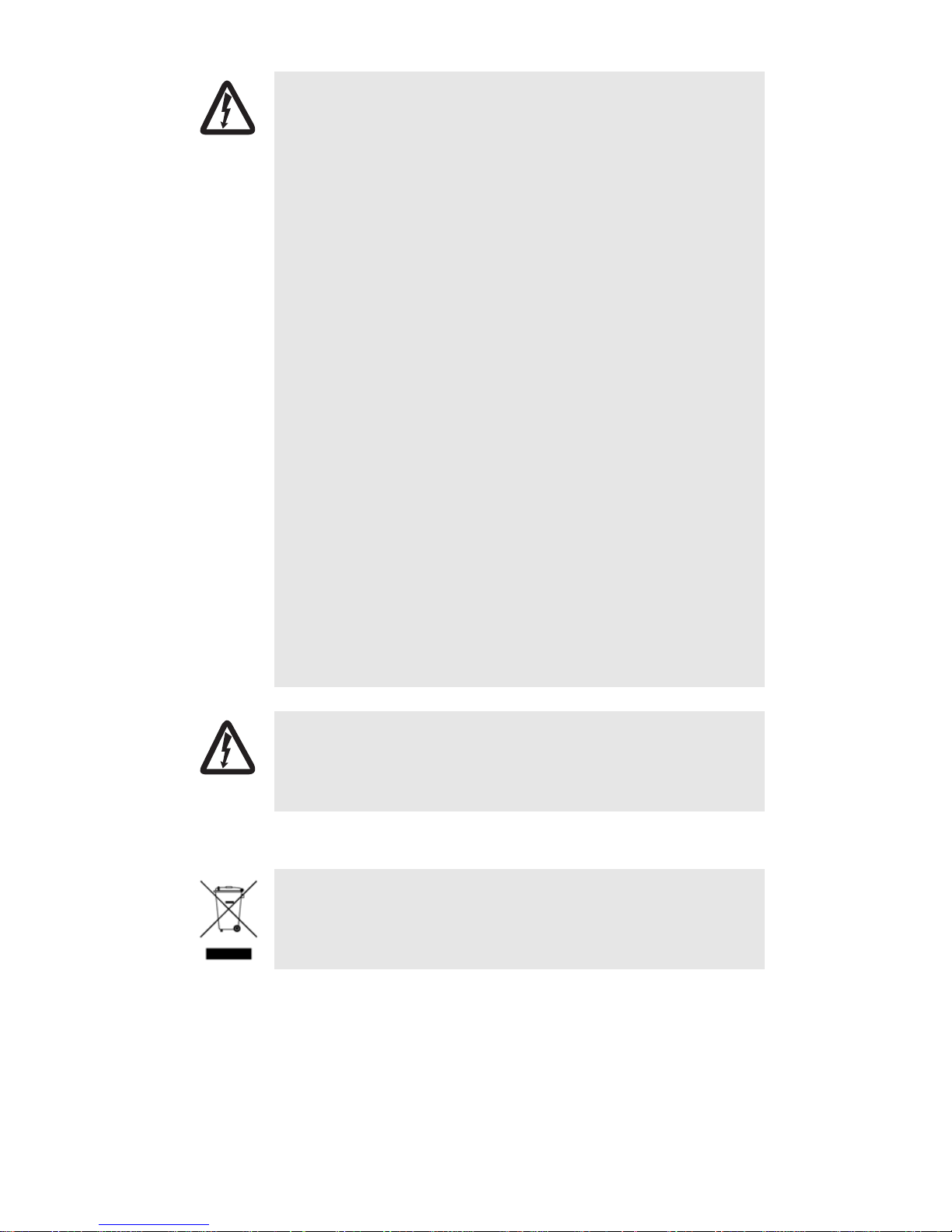
2.0 Power up the CL1314R
The CL1314R comes with either an external AC or external DC power supply.
Figure 1. Power Supply Installation
2.1 Models with external AC adapter
To connect the AC power supply, determine the positive lead and negative lead on the power adapter. Insert the
positive lead into the opening on the terminal block labeled + and the negative lead into the opening on the terminal block labeled -. Tighten the screws on the block to secure the wires. The CL1314R powers up as soon as it
is connected to an AC power source—there is no power switch.
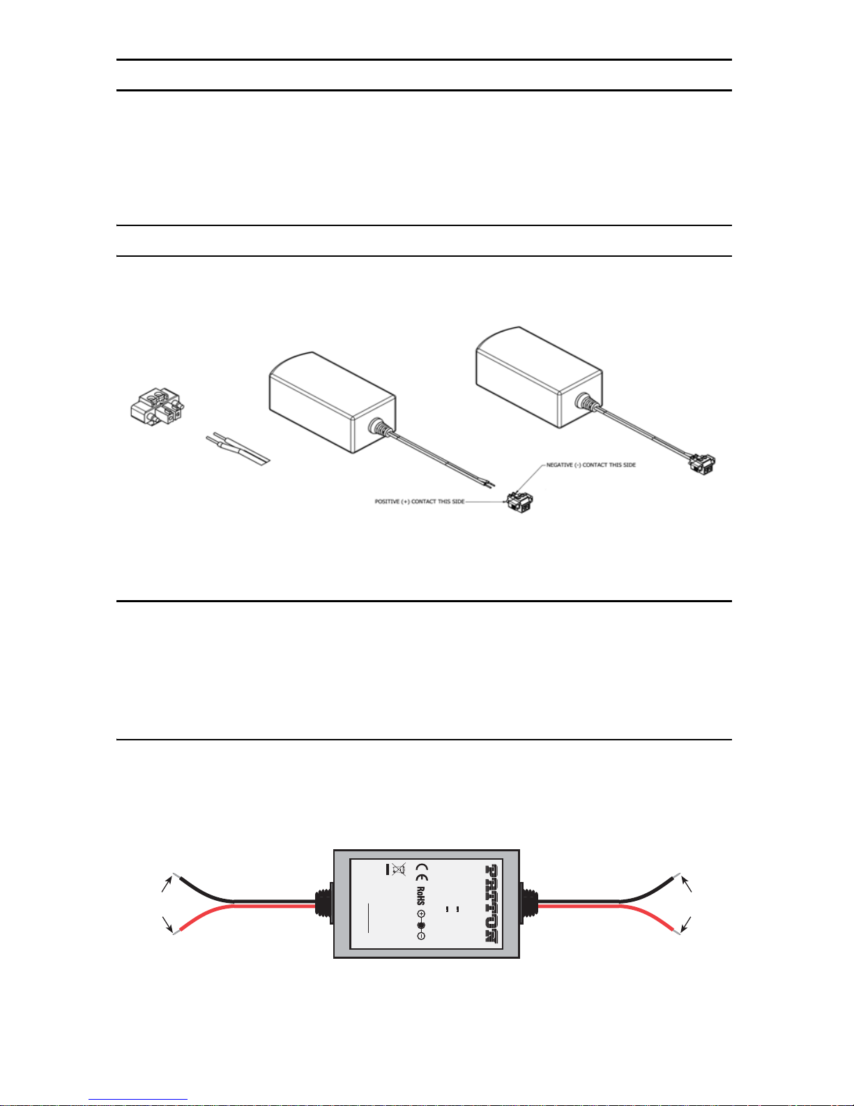
2.2 Models with external DC power supply
The 36-60 VDC DC to DC adapter is supplied with the DC version of the CL1314R. The black and red leads on one
end of the power supply plug into a DC source (nominal 48VDC), and the leads on the other end connect to the
terminal block power connector on the CL1314R.
Black lead (-V)
Red lead (+V)
To Terminal Block
Power Connector
-Vin
+Vin
S/N: G01234567890
MADE IN CHINA BY SUNNY
SWITCHING POWER SUPPLY
MODEL : SYD1106-0505
INPUT : 36-60V 0.2A MAX
OUTPUT : +5V 1.0A
OUTPUT POWER : 5W MAX
-Vin
+Vin
To -48VDC
Source
Black lead (-V)
Red lead (+V)
CopperLink Model 1314R Quick Start Guide 3
Figure 2. DC Power Supply
Page 4

2.3 Power up indication
Verify that the Power LED on the front panel illuminates and remains lit.
CopperLink™ Line Interface
Power LED
Line Link LED
Ethernet Port 1
Ethernet Port 0
Ethernet Port 0 Link LED
Ethernet Port 1 Link LED
Reset button
Figure 3. CL1314R front panel
3.0 Connect the CopperLink interface
1. Obtain single-twisted-pair cable with an RJ-45 plug connector at each end.
2. Plug one end of the cable into the RJ-45 socket (labeled Line) on the CopperLink. Verify that the other
end of the cable is connected to the Line port on other CopperLink and that the port is correctly configured.
3. When a link is established, the Line Link LED will turn on.
4.0 Connect the Ethernet port(s)
The RJ-45 ports labeled Eth 0 and Eth 1 are the Auto-MDIX 10/100Base-T interface. These ports are designed to
connect directly to a 10/100Base-T device or network. You may connect this port to a hub or PC using a straight
through or crossover cable that is up to 328 ft long.
4 CopperLink Model 1314R Quick Start Guide
Page 5

5.0 Additional information
For detailed information about installing, configuring, and operating the CopperLink, refer to the CopperLink
Model 1314R User Manual at www.patton.com/manuals/CL1314R.pdf.
A.0 Compliance Information
A.1 Compliance
EMC:
•
FCC Part 15, Class A
•
EN55022, Class A
•
EN55024
Safety:
•
UL 60950-1/CSA C22.2 N0. 60950-1
•
IEC/EN60950-1
1.2 Radio and TV Interference (FCC Part 15)
This equipment generates and uses radio frequency energy, and if not installed and used properly—that is, in
strict accordance with the manufacturer's instructions—may cause interference to radio and television reception. This equipment has been tested and found to comply with the limits for a Class A computing device in accordance with the specifications in Subpart B of Part 15 of FCC rules, which are designed to provide reasonable
protection from such interference in a commercial installation. However, there is no guarantee that interference
will not occur in a particular installation. If the equipment causes interference to radio or television reception,
which can be determined by disconnecting the cables, try to correct the interference by one or more of the following measures: moving the computing equipment away from the receiver, re-orienting the receiving antenna,
and/or plugging the receiving equipment into a different AC outlet (such that the computing equipment and
receiver are on different branches).
A.3 EC Declaration of Conformity
(See section A.4 “EG-Konformitätserklärung” for German version.)
Product Description: CopperLink Model 1314R
This equipment conforms to the requirements of Council Directive 1999/5/EC on the approximation of the laws
of the member states relating to Radio and Telecommunication Terminal Equipment and the mutual recognition
of their conformity.
The safety advice in the documentation accompanying the products shall be obeyed.
The conformity to the above directive is indicated by the CE sign on the device.
The signed Declaration of Conformity can be downloaded from www.patton.com/certifications/.
CopperLink Model 1314R Quick Start Guide 5
Page 6

A.4 EG-Konformitätserklärung
(see section A.3 “EC Declaration of Conformity” for English version)
Produktbezeichnung: CopperLink Model 1314R
Die bezeichneten Produkte stimmen in der von uns in Verkehr gebrachten Ausführung mit den Vorschriften folgender Richtlinie überein:
R&TTE 1999/5/EG
Richtlinie des europäischen Parlaments und des Rates zur Angleichung der Rechtsvorschriften der
Mitgliedstaaten über Funkanlagen und Telekommunikations-Endeinrichtungen und die gegenseitige
Anerkennung ihrer Konformität.
Die Sicherheitshinweise in der mitgelieferten Produktdokumentation sind zu beachten.
Die Konformität mit der oben erwähnten Richtlinie wird durch das CE-Zeichen auf dem
Gerät bestätigt.
Die unterzeichnete Konformitätserklärung kann heruntergeladen werden von: www.patton.com/
certifications/.
A.5 Authorized European Representative
D R M Green
European Compliance Services Limited.
Oakdene House, Oak Road
Watchfield, Swindon, Wilts SN6 8TD, UK
6 CopperLink Model 1314R Quick Start Guide
Page 7

Copyright statement
Copyright © 2012, Patton Electronics Company. All rights reserved.
The information in this document is subject to change without notice. Patton Electronics assumes no
liability for errors that may appear in this document.
Trademarks statement
The term CopperLink is a trademark of Patton Electronics Company. All other trademarks presented in this docu-
ment are the property of their respective owners.
Patton support headquarters in the USA
•
Online support: Available at www.patton.com
•
E-mail support: E-mail sent to support@patton.com will be answered within 1 business day
•
Telephone support: Standard telephone support is available five days a week—from 8:00 am to
5:00 pm EST (1300 to 2200 UTC/GMT)—by calling +1 (301) 975-1007
•
Support via VoIP: Contact Patton free of charge by using a VoIP ISP phone to call sip:support@patton.com
•
Fax: +1 (253) 663-5693
Alternate Patton support for Europe, Middle East, and Africa (EMEA)
•
Telephone support: Standard telephone support is available five days a week—from 8:00 am to
5:00 pm CET (0900 to 1800 UTC/GMT)—by calling +41 (0)31 985 25 55
•
Fax: +41 (0)31 985 25 26
Note For additional service and support information, refer to the “Contacting Patton for assistance” chapter
of the CopperLink Model 1314R User Manual available online at www.patton.com/manuals/
CL1314R.pdf.
Warranty, Trademark, & Compliance Information
For warranty, trademark and compliance information, refer to the CopperLink Model 1314R User Manual available
online at www.patton.com/manuals/CL1314R.pdf.
CopperLink Model 1314R Quick Start Guide 7
Page 8

NOTES
____________________________________________________________________
____________________________________________________________________
____________________________________________________________________
____________________________________________________________________
____________________________________________________________________
____________________________________________________________________
____________________________________________________________________
____________________________________________________________________
____________________________________________________________________
____________________________________________________________________
____________________________________________________________________
____________________________________________________________________
____________________________________________________________________
____________________________________________________________________
____________________________________________________________________
____________________________________________________________________
8 CopperLink Model 1314R Quick Start Guide
 Loading...