

Patton CopperLink 1314MDE Quick Start Manual

CopperLink™ Model 1314MDE
Ruggedized Multi-Drop Ethernet
Extender & Repeater
Quick Start Guide
Important
intended nor approved for use in an industrial or residential environment.
REGULATORY MODEL NUMBER: 03340D4-001
Part Number: 07MCL1314MDE-QS, Rev. A
Revised: August 10, 2012
—This is a Class A device and is intended for use in a light industrial environment. It is not
Sales Office: +1 (301) 975-1000
Technical Support: +1 (301) 975-1007
E-mail: support@patton.com
WWW: www.patton.com
WARNING
• Do not open the device when the power cord is connected. For systems without a power switch and without an external power
adapter, line voltages are present within the device when the power
cord is connected.
• For devices with an external power adapter, the power adapter shall
be a listed Limited Power Source The mains outlet that is utilized to
power the device shall be within 10 feet (3 meters) of the device,
shall be easily accessible, and protected by a circuit breaker in compliance with local regulatory requirements.
• For AC powered devices, ensure that the power cable used meets all
applicable standards for the country in which it is to be installed.
• For AC powered devices which have 3 conductor power plugs (L1, L2
& GND or Hot, Neutral & Safety/Protective Ground), the wall outlet
(or socket) must have an earth ground.
• For DC powered devices, ensure that the interconnecting cables are
rated for proper voltage, current, anticipated temperature, flammability, and mechanical serviceability.
• WAN, LAN & PSTN ports (connections) may have hazardous voltages
present regardless of whether the device is powered ON or OFF.
PSTN relates to interfaces such as telephone lines, FXS, FXO, DSL,
xDSL, T1, E1, ISDN, Voice, etc. These are known as “hazardous network voltages” and to avoid electric shock use caution when working
near these ports. When disconnecting cables for these ports, detach
the far end connection first.
• Do not work on the device or connect or disconnect cables during periods of lightning activity.
This device is NOT intended nor approved for connection to the PSTN. It
is intended only for connection to customer premise equipment.
WARNING
In accordance with the requirements of council directive 2002/96/EC on
Waste of Electrical and Electronic Equipment (WEEE), ensure that at endof-life you separate this product from other waste and scrap and deliver
to the WEEE collection system in your country for recycling.
2 CopperLink Model 1314MDE Quick Start Guide
1.0 Configure the DIP Switches
To use DIP-switch configuration, you must first set the DIP switches to a position other than all OFF or all ON
before powering-up the CopperLink. To configure your CL1314MDE using the DIP switches, refer to the section
entitled “Hardware (DIP-switch) configuration” in the CopperLink Model 1314MDE User Manual.
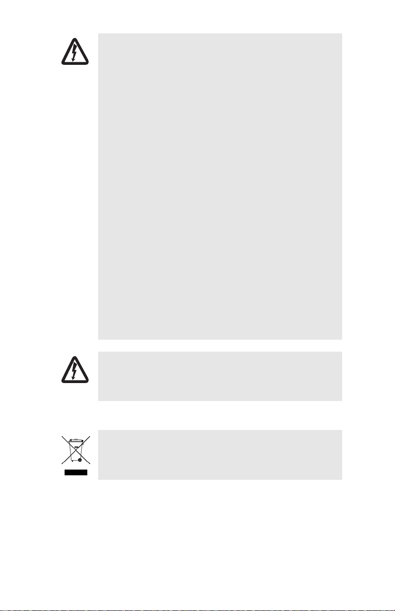
2.0 Power up the CL1314MDE
The CL1314MDE comes with either an external AC or external DC power supply.
Figure 1. Power Supply Installation
2.1 Models with external AC adapter
To connect the AC power supply, determine the positive lead and negative lead on the power adapter. Insert the
positive lead into the opening on the terminal block labeled + and the negative lead into the opening on the terminal block labeled -. Tighten the screws on the block to secure the wires. The CL1314MDE powers up as soon as
it is connected to an AC power source—there is no power switch.
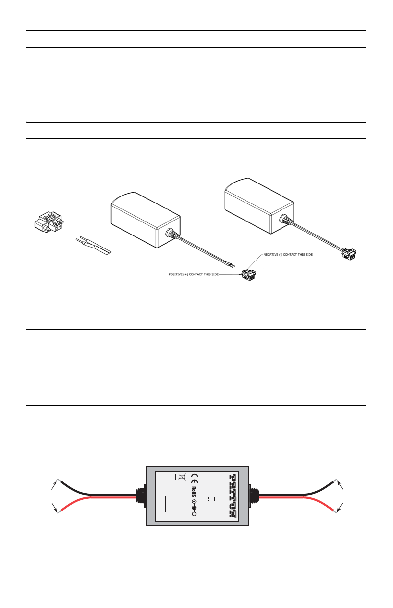
2.2 Models with external DC power supply
The 36-60 VDC DC to DC adapter is supplied with the DC version of the CL1314MDE. The black and red leads on
one end of the power supply plug into a DC source (nominal 48VDC), and the leads on the other end connect to
the terminal block power connector on the CL1314MDE.
To Terminal Block
Power Connector
S/N: G01234567890
Black lead (-V)
Red lead (+V)
-Vin
+Vin
MADE IN CHINA BY SUNNY
Figure 2. DC Power Supply
CopperLink Model 1314MDE Quick Start Guide 3
MODEL : SYD1106-0505
INPUT : 36-60V 0.2A MAX
OUTPUT : +5V 1.0A
OUTPUT POWER : 5W MAX
SWITCHING POWER SUPPLY
-Vin
+Vin
To -48VDC
Source
Black lead (-V)
Red lead (+V)
 Loading...