

Page 1
Model 6476
ForeFront FullPipe
Chassis Assembly
User Guide
Sales Office: +1 (301) 975-1000
Technical Support: +1 (301) 975-1007
E-mail: support@patton.com
URL: www.patton.com
Document Number: 12002U2-001 Rev. B
Part Number: 07M6476
Revised: May 12, 2006
Page 2

Patton Electronics Company, Inc.
7622 Rickenbacker Drive
Gaithersburg, MD 20879 USA
tel: +1 (301) 975-1000
fax: +1 (301) 869-9293
support: +1 (301) 975-1007
url: www.patton.com
e-mail: support@patton.com
Copyright Statement
Copyright © 2003, Patton Electronics Company. All rights reserved.
Trademark Statement
The terms ForeFront and FullPipe are trademarks of Patton Electronics Company.
CompactPCI and PICMG are registered trademarks of the PCI Industrial Computer
Manufacturers Group. All other trademarks presented in this document are the property of their respective owners.
Notices
The information contained in this document is not designed or intended for use as
critical components in human life-support systems, equipment used in hazardous
environments, or nuclear control systems. Patton Electronics Company disclaims any
express or implied warranty of fitness for such uses.
The information in this document is subject to change without notice. Patton Electronics assumes no liability for errors that may appear in this document.
Any software described in this document is furnished under license and may be used or
copied only in accordance with the terms of such license.
Page 3

Summary Table of Contents
1 Introduction.................................................................................................................................................. 14
2 Chassis specifications .................................................................................................................................... 16
3 System Architecture....................................................................................................................................... 26
4 Installation checklist ..................................................................................................................................... 34
5 Maintenance.................................................................................................................................................. 39
6 Contacting Patton for assistance ................................................................................................................... 41
A Compliance information .............................................................................................................................. 44
B Glossary of Terms ......................................................................................................................................... 47
3
Page 4

Contents
Summary Table of Contents ........................................................................................................................... 3
Contents ......................................................................................................................................................... 4
List of Figures ................................................................................................................................................. 7
List of Tables .................................................................................................................................................. 8
About this guide .....................................................................................................................................................9
Audience................................................................................................................................................................. 9
Structure................................................................................................................................................................. 9
Precautions ........................................................................................................................................................... 10
Safety when working with electricity ...............................................................................................................10
Style conventions used in this document............................................................................................................... 11
Typographical conventions used in this document................................................................................................ 11
General conventions .......................................................................................................................................12
Mouse conventions .........................................................................................................................................12
Bibliography ......................................................................................................................................................... 12
1 Introduction.................................................................................................................................................. 14
Product features and benefits.................................................................................................................................15
About Patton Electronics Company ......................................................................................................................15
2 Chassis specifications .................................................................................................................................... 16
4U CPCI subrack..................................................................................................................................................17
Description of chassis front side.............................................................................................................................17
Description of chassis rear side...............................................................................................................................19
Electromagnetic compatibility (EMC)...................................................................................................................20
Electrostatic discharge (ESD) protection................................................................................................................21
Fan tray assembly ..................................................................................................................................................23
Chassis system specifications..................................................................................................................................24
Power considerations .............................................................................................................................................24
Specifications ..................................................................................................................................................25
3 System Architecture....................................................................................................................................... 26
Board front panels .................................................................................................................................................27
Transition Boards..................................................................................................................................................27
Pin and socket connectors......................................................................................................................................29
J1/P1 & J2/P2 connectors ...............................................................................................................................30
J3/P3 through J5/P5 connector .......................................................................................................................30
Reserved Pins ..................................................................................................................................................30
Power Pins ......................................................................................................................................................30
Backplane Architecture..........................................................................................................................................30
Backplane power distribution ................................................................................................................................32
External power connections ............................................................................................................................32
Hot-Swap Capability.............................................................................................................................................33
4
Page 5

5
Model 6476 User Guide
Contents
4 Installation checklist ..................................................................................................................................... 34
4U quick set-up checklist.......................................................................................................................................35
Power cable installation ...................................................................................................................................36
Installing the power cables—AC unit ........................................................................................................36
Installing the power cables—DC unit .......................................................................................................36
Grounding the Model 6476—AC and DC units ......................................................................................37
Changing the VI/O configuration jumper .......................................................................................................37
Optional Frame Ground/Signal Ground Connect ..........................................................................................37
5 Maintenance.................................................................................................................................................. 39
Preventive Maintenance.........................................................................................................................................40
Cleaning the fan filter .....................................................................................................................................40
Troubleshooting....................................................................................................................................................40
System won’t power up ...................................................................................................................................40
6 Contacting Patton for assistance ................................................................................................................... 41
Introduction..........................................................................................................................................................42
Contact information..............................................................................................................................................42
Patton support headquarters in the USA .........................................................................................................42
Alternate Patton support for Europe, Middle East, and Africa (EMEA) ..........................................................42
Warranty Service and Returned Merchandise Authorizations (RMAs)...................................................................42
Warranty coverage ..........................................................................................................................................42
Out-of-warranty service .............................................................................................................................43
Returns for credit ......................................................................................................................................43
Return for credit policy .............................................................................................................................43
RMA numbers ................................................................................................................................................43
Shipping instructions ................................................................................................................................43
A Compliance information .............................................................................................................................. 44
Radio and TV Interference (FCC Part 15) ............................................................................................................45
EC Declaration of Conformity ..............................................................................................................................45
FCC Part 68 (ACTA) Statement ...........................................................................................................................45
Industry Canada Notice ........................................................................................................................................46
B Glossary of Terms ......................................................................................................................................... 47
C ...........................................................................................................................................................................48
CFM ...............................................................................................................................................................48
CSA ................................................................................................................................................................48
CT ..................................................................................................................................................................48
D...........................................................................................................................................................................48
Dual Redundant .............................................................................................................................................48
E............................................................................................................................................................................48
ECTF .............................................................................................................................................................48
EIA .................................................................................................................................................................48
EMC ...............................................................................................................................................................48
EMI ................................................................................................................................................................48
Page 6

6
Model 6476 User Guide
EN ..................................................................................................................................................................48
Enumeration ...................................................................................................................................................48
ESD ................................................................................................................................................................48
Eurocard .........................................................................................................................................................48
H...........................................................................................................................................................................48
Hot-Swap .......................................................................................................................................................48
HP ..................................................................................................................................................................48
I.............................................................................................................................................................................49
IDE ................................................................................................................................................................49
IEC .................................................................................................................................................................49
IEEE ...............................................................................................................................................................49
IN/C ...............................................................................................................................................................49
ISA ..................................................................................................................................................................49
K ...........................................................................................................................................................................49
Keying ............................................................................................................................................................49
N...........................................................................................................................................................................49
N+1 Redundant ..............................................................................................................................................49
NEBS .............................................................................................................................................................49
NP ..................................................................................................................................................................49
P............................................................................................................................................................................49
PCI .................................................................................................................................................................49
PCI SIG ..........................................................................................................................................................49
PICMG ..........................................................................................................................................................49
Platform ..........................................................................................................................................................49
S............................................................................................................................................................................49
SELV ..............................................................................................................................................................49
S-HAZ ............................................................................................................................................................49
Shroud ............................................................................................................................................................50
T ...........................................................................................................................................................................50
TDM ..............................................................................................................................................................50
TNV ...............................................................................................................................................................50
U...........................................................................................................................................................................50
U ....................................................................................................................................................................50
W..........................................................................................................................................................................50
Warm-Swap ....................................................................................................................................................50
Contents
Page 7

List of Figures
1 Model 6476 . . . . . . . . . . . . . . . . . . . . . . . . . . . . . . . . . . . . . . . . . . . . . . . . . . . . . . . . . . . . . . . . . . . . . . . . . . . 17
2 Model 6476 ForeFront FullPipe Chassis . . . . . . . . . . . . . . . . . . . . . . . . . . . . . . . . . . . . . . . . . . . . . . . . . . . . . . 18
3 Front view of chassis . . . . . . . . . . . . . . . . . . . . . . . . . . . . . . . . . . . . . . . . . . . . . . . . . . . . . . . . . . . . . . . . . . . . . 19
4 Rear view of chassis . . . . . . . . . . . . . . . . . . . . . . . . . . . . . . . . . . . . . . . . . . . . . . . . . . . . . . . . . . . . . . . . . . . . . . 20
5 AC and DC rear power entry modules . . . . . . . . . . . . . . . . . . . . . . . . . . . . . . . . . . . . . . . . . . . . . . . . . . . . . . . 20
6 EMC strip and gasket on chassis and cards . . . . . . . . . . . . . . . . . . . . . . . . . . . . . . . . . . . . . . . . . . . . . . . . . . . . 21
7 Alignment/ESD pin on card handle . . . . . . . . . . . . . . . . . . . . . . . . . . . . . . . . . . . . . . . . . . . . . . . . . . . . . . . . . 22
8 Model 6470-FT fan tray assembly . . . . . . . . . . . . . . . . . . . . . . . . . . . . . . . . . . . . . . . . . . . . . . . . . . . . . . . . . . 23
9 Front panel—6U front-entry card . . . . . . . . . . . . . . . . . . . . . . . . . . . . . . . . . . . . . . . . . . . . . . . . . . . . . . . . . . 27
10 Front/rear boards and backplane interface . . . . . . . . . . . . . . . . . . . . . . . . . . . . . . . . . . . . . . . . . . . . . . . . . . . . . 28
11 J1 through J5 connectors on the 6U card . . . . . . . . . . . . . . . . . . . . . . . . . . . . . . . . . . . . . . . . . . . . . . . . . . . . . 29
12 Rear view of chassis showing the midplane/backplane . . . . . . . . . . . . . . . . . . . . . . . . . . . . . . . . . . . . . . . . . . . . 31
13 IEC-320 connector and grounding stud locations . . . . . . . . . . . . . . . . . . . . . . . . . . . . . . . . . . . . . . . . . . . . . . . 36
14 DC connector, -DC and +DC input view . . . . . . . . . . . . . . . . . . . . . . . . . . . . . . . . . . . . . . . . . . . . . . . . . . . . . 37
15 Frame ground connected to signal ground . . . . . . . . . . . . . . . . . . . . . . . . . . . . . . . . . . . . . . . . . . . . . . . . . . . . 38
7
Page 8

List of Tables
1 General conventions . . . . . . . . . . . . . . . . . . . . . . . . . . . . . . . . . . . . . . . . . . . . . . . . . . . . . . . . . . . . . . . . . . . . . 12
2 Mouse conventions . . . . . . . . . . . . . . . . . . . . . . . . . . . . . . . . . . . . . . . . . . . . . . . . . . . . . . . . . . . . . . . . . . . . . . 12
3 Fan tray specifications . . . . . . . . . . . . . . . . . . . . . . . . . . . . . . . . . . . . . . . . . . . . . . . . . . . . . . . . . . . . . . . . . . . . 23
4 4U chassis materials specifications . . . . . . . . . . . . . . . . . . . . . . . . . . . . . . . . . . . . . . . . . . . . . . . . . . . . . . . . . . . 24
5 Power input and power supplies . . . . . . . . . . . . . . . . . . . . . . . . . . . . . . . . . . . . . . . . . . . . . . . . . . . . . . . . . . . . 24
6 . . . . . . . . . . . . . . . . . . . . . . . . . . . . . . . . . . . . . . . . . . . . . . . . . . . . . . . . . . . . . . . . . . . . . . . . . . . . . . . . . . . . . 25
7 Power specifications . . . . . . . . . . . . . . . . . . . . . . . . . . . . . . . . . . . . . . . . . . . . . . . . . . . . . . . . . . . . . . . . . . . . . 32
8 Description of rear interface panel connectors . . . . . . . . . . . . . . . . . . . . . . . . . . . . . . . . . . . . . . . . . . . . . . . . . . 32
8
Page 9

About this guide
This manual is a comprehensive hardware reference tool for the Patton Electronics 4U 6476 Redundant Backplane/Midplane and Chassis line of products.
Audience
This guide is intended for the following users:
• System developers installing and integrating the products into their systems
• Operators
• Installers
• Maintenance technicians
Structure
This guide contains the following chapters and appendices:
• Chapter 1, "Introduction" on page 14—provides an overview of the product, about Patton Electronics,
warranty, and service information.
• Chapter 2, "Chassis specifications" on page 16—provides an overview of the chassis features.
• Chapter 3, "System Architecture" on page 26—provides an overview of CompactPCI specifications, as well
as a more in-depth description of the product’s features.
• Chapter 4, "Installation checklist" on page 34—provides a quick set-up checklist for installing the
Model 6476.
• Chapter 5, "Maintenance" on page 39—provides a quick set-up checklist, tips for troubleshooting, war-
ranty information, and where to get help.
• Appendix A, "Compliance information" on page 44—contains compliance information for the
Model 6476
• Appendix B, "Glossary of Terms" on page 47—defines terms and acronyms used in this document.
For best results, read the contents of this guide before you install the enclosure.
9
Page 10

10
CAUTION
WARNING
WARNING
Model 6476 User Guide
Precautions
Notes, cautions, and warnings, which have the following meanings, are used throughout this guide to help you
become aware of potential problems. Warnings are intended to prevent safety hazards that could result in personal injury. Cautions are intended to prevent situations that could result in property damage or
impaired functioning.
Note
IMPORTANT
CAUTION
CAUTION
A note presents additional information or interesting sidelights.
The alert symbol and IMPORTANT heading calls attention to
important information.
The alert symbol and CAUTION heading indicate a potential hazard. Strictly follow the instructions to avoid property damage.
The shock hazard symbol and CAUTION heading indicate a
potential electric shock hazard. Strictly follow the instructions to
avoid property damage caused by electric shock.
This symbol and the CAUTION heading indicates a situation
where damage to equipment can be caused by electrostatic discharge.
The alert symbol and WARNING heading indicate a potential safety hazard.
Strictly follow the warning instructions to avoid personal injury.
The shock hazard symbol and WARNING heading indicate a potential electric
shock hazard. Strictly follow the warning instructions to avoid injury caused
by electric shock.
Safety when working with electricity
This device contains no user serviceable parts. The equipment shall be
returned to Patton Electronics for repairs, or repaired by qualified
service personnel.
Page 11
Model 6476 User Guide
11
Mains Voltage: Do not open the case when the power cord is attached. Disconnect the power supply cord before servicing. For systems without a power
switch, line voltages are present within the power supply when the power
cords are connected. The mains outlet that is utilized to power the devise shall
be within 10 feet (3 meters) of the device, shall be easily accessible, and protected by a circuit breaker.
For AC powered units, ensure that the power cable used with this device
meets all applicable standards for the country in which it is to be installed,
and that it is connected to a wall outlet which has earth ground.
Hazardous network voltages are present in WAN ports regardless of whether
power to the Smart-DTA is ON or OFF. To avoid electric shock, use caution
when near WAN ports. When detaching cables, detach the end away from the
ForeFront device first.
Do not work on the system or connect or disconnect cables during periods of
lightning activity.
In accordance with the requirements of council directive 2002/
96/EC on Waste of Electrical and Electronic Equipment (WEEE),
ensure that at end-of-life you separate this product from other
waste and scrap and deliver to the WEEE collection system in
your country for recycling.
Style conventions used in this document
Tables contain information of a descriptive nature. For example, pin assignments or signal description.
Cross-references, figure titles, and table titles are hyperlinked. This means that if you have the on-line version of
this document, you can click on the cross-reference and it will “jump” you to that reference within the document.
This feature only works with references to sections/tables/figures within this document. References to other documents (for example, PICMG 2.5 R1.0 CompactPCI Computer Telephony Specification ) are not hyperlinked.
The symbols “/” and “#” indicate signals that are active low.
Specific safety-related terms, traceable to certain safety regulatory agency requirements (i.e., IEC950 and harmonized derivative specifications) are used within this manual. Refer to the referenced document for a definition of these terms.
Typographical conventions used in this document
This section describes the typographical conventions and terms used in this guide.
Page 12
12
Model 6476 User Guide
General conventions
The procedures described in this manual use the following text conventions:
Table 1. General conventions
Convention Meaning
Garamond blue type
Futura bold type
Italicized Futura type
Futura type Indicates the names of fields or windows.
Garamond bold type
< > Angle brackets indicate function and keyboard keys, such as <SHIFT>,
Are you ready?
% dir *.* Bold Courier font indicates where the operator must type a response or
Indicates a cross-reference hyperlink that points to a figure, graphic,
table, or section heading. Clicking on the hyperlink jumps you to the reference. When you have finished reviewing the reference, click on the
Go to Previous View button in the Adobe® Acrobat® Reader
toolbar to return to your starting point.
Indicates the names of menu bar options.
Indicates the names of options on pull-down menus.
Indicates the names of command buttons that execute an action.
<CTRL>, <C>, and so on.
All system messages and prompts appear in the
system would display them.
command
Courier font as the
Mouse conventions
The following conventions are used when describing mouse actions:
Table 2. Mouse conventions
Convention Meaning
Left mouse button
Right mouse button This button refers the secondary or rightmost mouse button (unless you have
Point This word means to move the mouse in such a way that the tip of the pointing
Click Means to quickly press and release the left or right mouse button (as instructed in
Double-click Means to press and release the same mouse button two times quickly
Drag This word means to point the arrow and then hold down the left or right mouse but-
This button refers to the primary or leftmost mouse button (unless you have
changed the default configuration).
changed the default configuration).
arrow on the screen ends up resting at the desired location.
the procedure). Make sure you do not move the mouse pointer while clicking a
mouse button.
ton (as instructed in the procedure) as you move the mouse to a new location.
When you have moved the mouse pointer to the desired location, you can release
the mouse button.
Bibliography
The following publications are used in conjunction with this manual.
• ECTF H.110 (CT Bus) Specification (Revision 1.0)
• CompactPCI Hot Swap Specification—PICMG 2.12 (Revision 1.0)
Page 13

13
Model 6476 User Guide
• CompactPCI Specification—PICMG 2.0 (Revision 3.0)
• Keying of CompactPCI Boards and Backplanes Specification—PICMG 2.10 (Revision 1.0)
• UL60950, Safety of Information Technology Equipment, including Electrical Business Equipment
• IEC 61076-4-101 (1995-05), Specification for 2mm Connector System
• IEEE 1101.10, IEEE Standard for Additional Mechanical Specifications for Microcomputers using IEEE
1101.1 Equipment Practice
Page 14

Chapter 1
Chapter contents
Product features and benefits.................................................................................................................................15
About Patton Electronics Company ......................................................................................................................15
Introduction
14
Page 15

15
Model 6476 User Guide
1 • Introduction
Product features and benefits
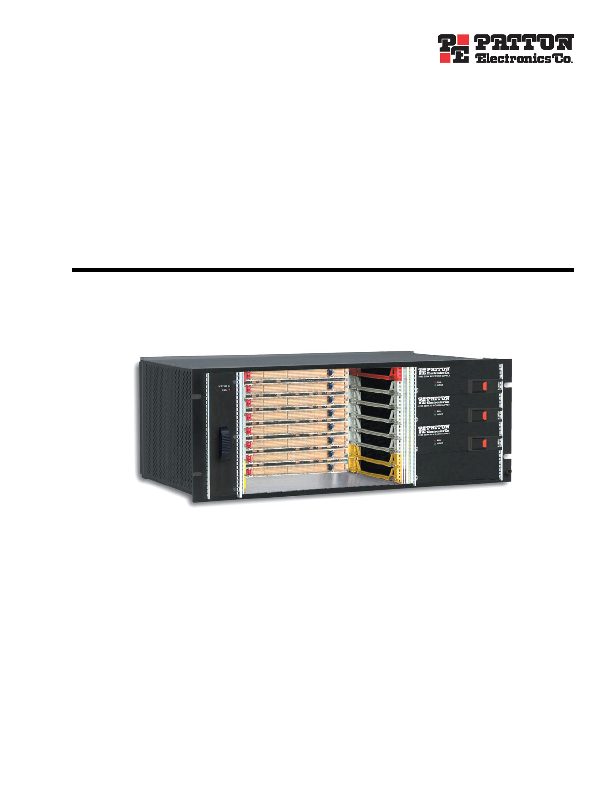
Thank you for purchasing Patton Electronics Co. Model 6476 ForeFront FullPipe Chassis with CPCI 4U
backplane/midplane. The Model 6476 FireFront FullPipe Chassis is a modular 6U x 19 inch rackmount subrack-type packaging system suitable for open bus architectures such as CPCI, or custom bus applications. The
base unit is adaptable to a wide array of product configurations.
The product offers a low cost, turnkey solution for customers desiring eight 4U x 160mm slots (a full CPCI
bus segment) in the least possible vertical rack space. The superior design also provides eight 3U x 160mm slots
to mount up to four Power Supply Modules configured for external DC or AC power input.
The rear of the chassis provides eight 6U x 80mm slots for CPCI transition modules. Cooling is provided by
the specially designed model 6470-FT plug-in fan tray module.
The Model 6476 ForeFront FullPipe Chassis complies with the PICMG 2.0 R3.0 CompactPCI Specification ,
and PICMG 2.5, ECTF H.110 (CT Bus) Specification (Rev. 1.0), making it an excellent choice for redundant,
fault tolerant applications
About Patton Electronics Company
Patton Electronics excels in the design, development and production of Embedded Data Communications and
Telecommunications Platforms based on open system bus architecture standards (for example, CPCI and
VME). These platforms form a significant part of the infrastructure for today’s information technology revolution—including the emergence of new packet-based (IP) global communication networks.
Datacom/Telecom platforms require robust and reliable packaging solutions that address key technology issues,
such as line density, thermal management, power distribution, scalability, and regulatory compliance. With an
increasing number of applications demanding downtime measured in minutes rather than hours, special consideration has to be given to enclosure system functionality. Patton Electronics’ full line of enclosure solutions
are designed specifically to meet industry’s stringent high availability requirements where redundant operation,
quick accessibility and high reliability are essential. Patton has a broad engineering background in the development of these technologies for advanced circuit and packet-switched telecommunications systems running
voice, data and video applications for commercial and government customers.
Patton offers a wide range of platforms consisting of standard rack/chassis, high speed backplane, power, thermal management, single board computer (SBC) and alarm/network interface products for commercial, voice/data communications, and government/military system
applications. Patton Electronics is ISO-9001 certified.
Product features and benefits
Page 16

Chapter 2
Chapter contents
4U CPCI subrack..................................................................................................................................................17
Description of chassis front side.............................................................................................................................17
Description of chassis rear side...............................................................................................................................19
Electromagnetic compatibility (EMC)...................................................................................................................20
Electrostatic discharge (ESD) protection................................................................................................................21
Fan tray assembly ..................................................................................................................................................23
Chassis system specifications..................................................................................................................................24
Power considerations .............................................................................................................................................24
Specifications ..................................................................................................................................................25
Chassis specifications
16
Page 17

17
✔
✔
Model 6476 User Guide
2 • Chassis specifications
4U CPCI subrack
The Model 6476 ForeFront FullPipe is a modular 4U x 19 inch rackmount subrack-type packaging system
designed for the ForeFront CompactPCI open bus architecture. The rugged, rack-mounted chassis system is
ideal for carrier-class, defense, industrial, enterprise, and commercial environments. The 6476 excels in its ease
of access, superior cooling, and power distribution. The base unit is adaptable to a wide array of product configurations.
Product features include:
Available in AC, DC, and mixed AC + DC power supply configurations
Fully compatible with all Patton ForeFront modules
✔ EMI shielding on entire assembly, with continuous chassis ground
✔ Lightweight and durable cold-rolled steel construction, suitable for rugged environments
✔ Only 11.70 in. (29.80 cm) deep
✔ Standard powder coating finish
✔ Front mounting flanges for 19 in. rack mount environments
Figure 1. Model 6476
Description of chassis front side
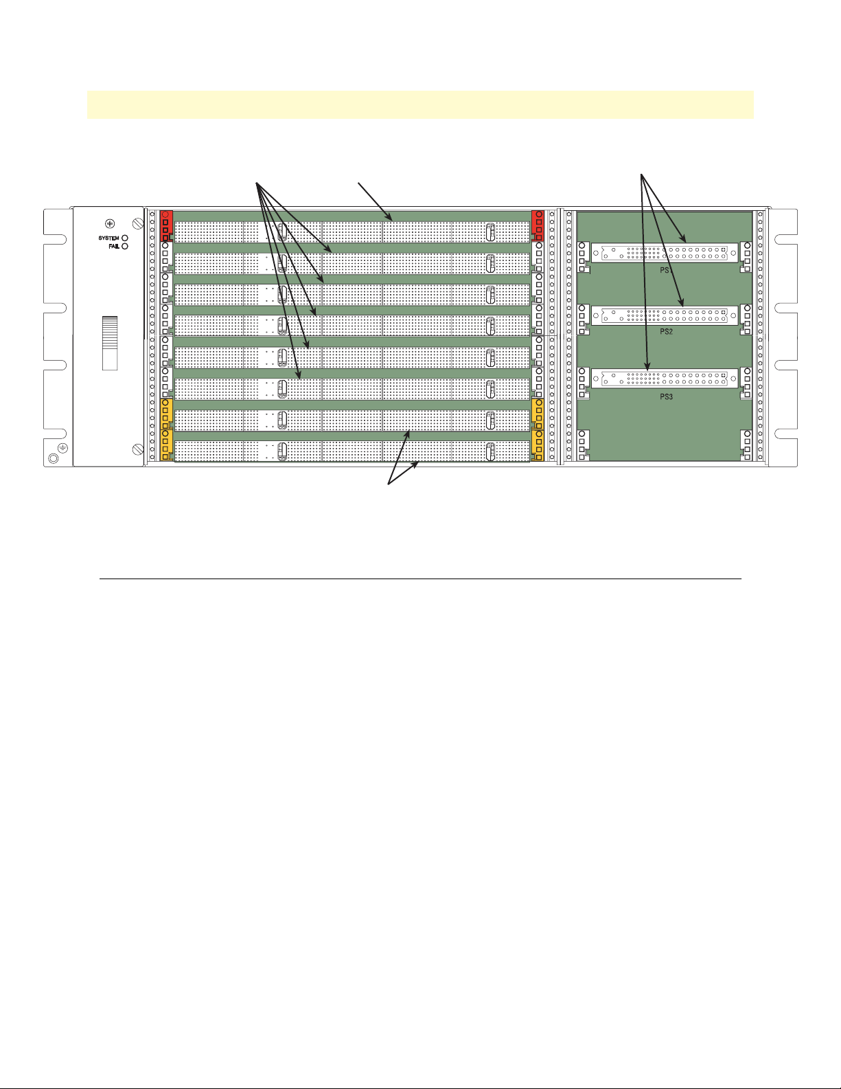
There are eight 6U x 160mm slots (a full CPCI bus segment) at the front of the chassis (see figure 2). Frontentry ForeFront modules, in accordance with PICMG 2.0 CompactPCI specifications, are plugged into these
slots.
4U CPCI subrack
Page 18

Model 6476 User Guide 2 • Chassis specifications
Rear 3U area
Alarm module
(alarm module,
rear power entry)
Power bay
(front 3U area)
Rear transition
module
Transition module area
(rear 6U area)
6U CPCI bus segment
(front 6U area)
SYSTEM
Power supply
module
FAIL
Front entry module
Fan tray assembly
Figure 2. Model 6476 ForeFront FullPipe Chassis
The front of the chassis also provides four slots suitable for 3Ux8HP ForeFront power supplies, model 6160
(DC) or 6165 (AC). These devices are described more completely in the 6160/6165 Users Manual.
All slots provide 4HP module spacing and are on 0.80 in. centers (except for the power supply slots, which are
offset 0.1” as per PICMG 2.11 standard). Card guides are molded plastic with metallic ESD contacts (see
“Electrostatic discharge (ESD) protection” on page 21) per CompactPCI PICMG 2.0 R3.0 & IEEE 1101.10.
Description of chassis front side 18
Page 19
Model 6476 User Guide 2 • Chassis specifications
Peripheral Slot
(Gray card guides)
System Slot
(Red card guides)
Switch Slot, Model 6511 only
(Yellow card guides)
Figure 3. Front view of chassis
Power Supply Slot
Description of chassis rear side
The rear of the chassis is divided into two areas:
• A set of eight 6U slots for ForeFront transition modules (see figure 2 on page 18). These modules typically
contain cable connections for I/O interfaces such as T1/E1 trunks, optical fiber trunks, DSL lines, Ethernet, etc.
• A set of 3U slots allocated for the following uses (see figure 4 on page 20):
- Power input modules—either Patton Model 6112/HOR (DC) or Patton Model 6117/HOR (AC) (see
figure 5 on page 20). These modules provide power input to the power supplies in the front of the chassis
(see figure 2 on page 18). Each input module provides input for two power supplies. The following configurations are possible:
■ Two DC input modules (supports up to 3DC supplies)
■ Two AC input modules (supports up to 3 AC supplies)
■ One AC, one DC input module (supports up to 2 DC and 1 AC supplies or up to 1 DC and 2 AC
supplies)
Description of chassis rear side 19
Page 20

Model 6476 User Guide 2 • Chassis specifications
Alarm Card Slot
Rear Power Entry SlotBlank panel Rear Transition Module Slots
Figure 4. Rear view of chassis
AC power module DC power module
Figure 5. AC and DC rear power entry modules
Electromagnetic compatibility (EMC)
The Model 6476 ForeFront FullPipe is designed to provide the highest level of EMC performance—in terms
of both interference and susceptibility. The chassis has the following design features to mitigate the effects of
electromagnetic interference (EMI):
• All gaskets, contacts, and contact surfaces are electrically conductive.
• The mating surfaces of the EMC chassis and the EMC plug-in unit front panels and/or optional EMC filler
panels are also conductive by use of gaskets/strips.
• All chassis and plug-in contact surfaces are connected to a common chassis ground.
Mating EMC gaskets and strips are used on the chassis, front panels of boards, and optional filler panels. An
EMC gasket is attached to the bottom of the chassis (front view), and an EMC strip is attached to the top.
Plug-in boards have the corresponding mates on the opposite side (see figure 6).
Electromagnetic compatibility (EMC) 20
Page 21

Model 6476 User Guide 2 • Chassis specifications
Figure 6. EMC strip and gasket on chassis and cards
The EMC strip on the left side of the board mates with the EMC gasket attached to the chassis when it is
plugged into the first slot. Each board mates together with corresponding gaskets/strips.
In addition, all aluminum components of the subrack are surface treated and conductive. Top, bottom, sides
and rear EMC covers provide mechanical protection and EMC shielding on the subrack. Retaining clips
ensure conductive connection.
The chassis contains an optional frame ground to signal ground jumper. By default, in all ForeFront FullPipe
products, this jumper is not installed. This means that frame ground (the electrical potential of the chassis shell
itself and all panels, screws, etc. that are connected to it) is electrically isolated from the signal ground (the electrical potential corresponding to “0 volts” with respect to the power supplies and cards in the chassis). Patton
Electronics recommends that this isolation be maintained, in order to improve the EMC characteristics of the
system and the integrity of the two distinct grounds.
See the chapter on installation and maintenance for further information on the jumper settings.
Electrostatic discharge (ESD) protection
The 6476 ForeFront FullPipe chassis provides ESD protection in compliance with IEEE 1101.10. ESD contacts are embedded inside and in the front section of card guides for making early as possible contact with a
discharge strip on one or both, the upper and/or lower edge of the plug-in board/module. Only the card guides
located at the bottom rail of the chassis (right vertical rail for the 4U chassis), both front and rear (when there
is a transition module present in the chassis), contain the ESD clips. The ESD clip in the card guide is connected to the Chassis GND (ground).
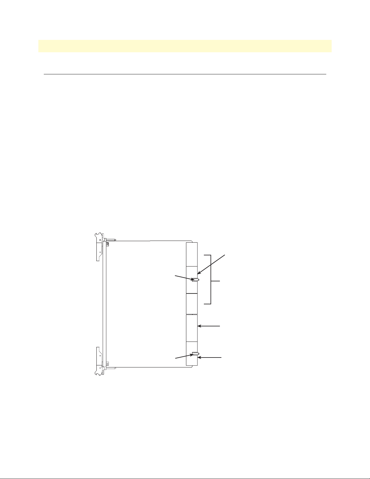
There is an alignment/ESD pin on the injector/ejector handle of boards (see figure 7).
Electrostatic discharge (ESD) protection 21
Page 22

Model 6476 User Guide 2 • Chassis specifications
Card handle
Alignment/ESD pin
Figure 7. Alignment/ESD pin on card handle
The alignment pin does the following:
• Ensures that the connectors are correctly aligned before they engage
• Provides solid/protected keying
• Provides board ESD contact
• Ensures that the EMC gasket is properly aligned (see “Electromagnetic compatibility (EMC)” on page 20)
• Ensures that when the board is inserted in the card guide, an integrated ESD clip discharges ESD from the
board to the right vertical rail chassis ground.
Electrostatic discharge (ESD) protection 22
Page 23
Model 6476 User Guide 2 • Chassis specifications
SYSTEM
FAIL
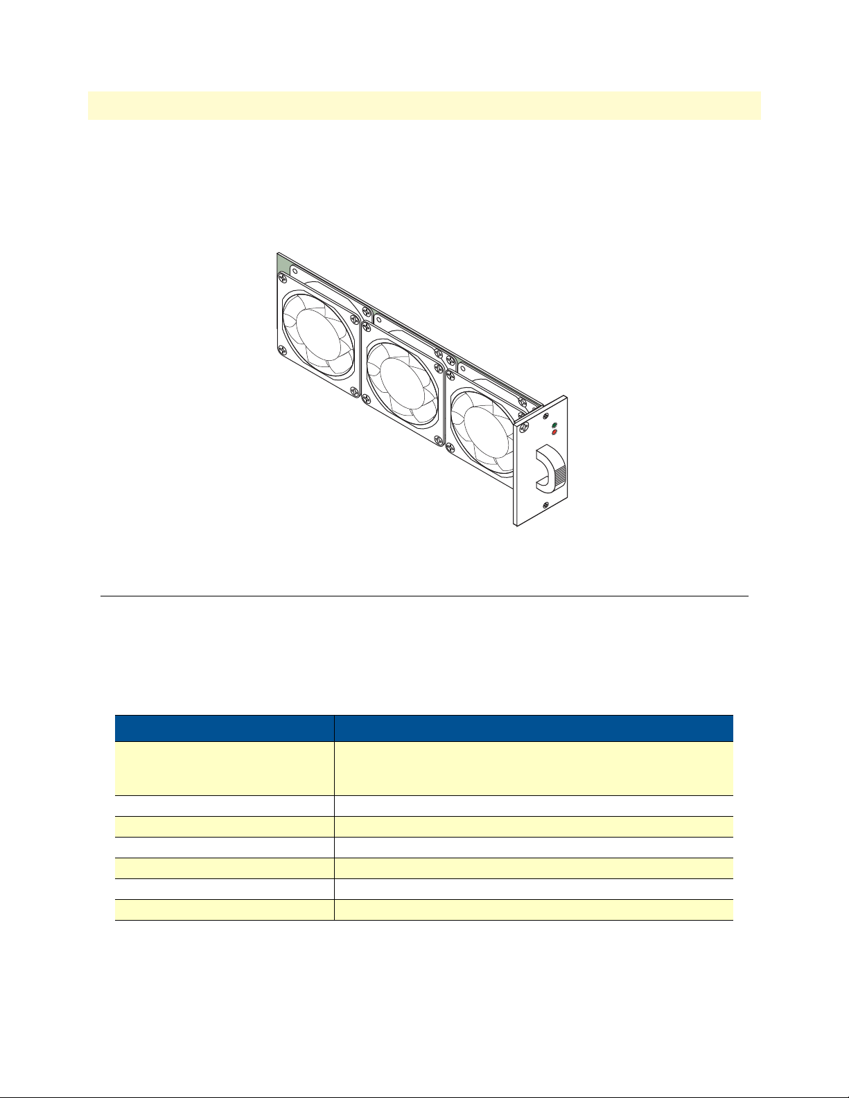
Figure 8. Model 6470-FT fan tray assembly
Fan tray assembly
Cooling is provided by the specially-designed, Patton Electronics Company, 6470-FT Plug-In Fan Tray Module (see figure 8). The unit utilizes six 12 VDC axial cooling fans which are positioned for optimum side-toside air flow through the subrack.
The fan tray is hot-swappable for air filter replacement.
Table 3. Fan tray specifications
Item Description
Physical Height: 7 in. (17.78 cm)
Width: 2.75 in. (6.98 cm)
Depth: 11.13 in. (28.27 cm)
Power requirements 1.3 A at 12 VDC
Performance 42.5 CFM per fan (quantity: 3 fans)
Reliability 7,000 hours at 122°F (50°C)
Operating environment 32–122°F (0–50°C), 5–95% relative humidity, non-condensing
Fan tray model no. 6470-FT
Replacement air filter part no. 6570-AF-6 (6-pack)
Fan tray assembly 23
Page 24

Model 6476 User Guide 2 • Chassis specifications
Chassis system specifications
A list of the 4U model 6476 chassis materials specifications is provided in table 4.
Table 4. 4U chassis materials specifications
Item Description
Physical
DC interface Rear DC interface panel includes dual ground lugs, -48V DC power
AC interface Rear AC interface panel includes: an IEC 320 AC inlet connector,
Slot configuration
Module keying and alignment 4HP module spacing, cardguide provides for keying and alignment
Card guides Molded plastic with snap-in ESD contacts for plug-in module and
Plug-in unit injector/ejector handles Subrack dimensional format accepts modules with injector/ejector
Operating environment 32–122°F (0–50°C), 5–95% relative humidity, non-condensing
• Height—4U (7 in./17.78 cm)
• Width—19 in. (standard EIA rack mount)
• Depth—11.70 in. (29.70 cm)
interface for N+N redundant power operation.
ground lug, power fuses.
• Front—6U x 160 mm slots, Qty: 8
• Rear—6U X 80 mm slots, Qty: 8
Slots are on 0.80 in. (2.0 cm) centers, except power slots are 1.6 in.
(4.1 cm) center
pin in accordance with IEEE 1101.10, section 6
injector/ejector handle alignment pin
handles as specified in IEEE 1101.10, section 8
Table 5. Power input and power supplies
Item Description
Power input DC: -48 VDC nominal (-36 to -75V)
AC: 115 - 230 VAC, 50–60 HZ
Maximum current DC: 7.0 A per power input
AC: 5.0 A per power supply
Power supply fusing DC: 250 V, 12.5 A, Slow blow (one fuse per PSU)
AC: 250 V, 5 A, Slow blow (one fuse per PSU)
Power considerations
For DC systems:
• An approved external source must be rated a maximum of 75 VDC, 7.0 A and provide over current protec-
tion upstream of the equipment.
• An approved disconnect device with a minimum 3.0 mm contact separation must be provided upstream of
the device and rated at least 75 VDC, 7.0 A and be located so it is accessible to the operator.
• This equipment shall be connected directly to the DC supply system bonding jumper from an earthing ter-
minal bar or bus to which the DC supply system earthing electrode is connected.
Chassis system specifications 24
Page 25

Model 6476 User Guide 2 • Chassis specifications
• This equipment shall be located in the same immediate area as any other equipment that has a connection
between the earthed conductor of the same DC supply circuit and the earthing conductor, and also the
point of earthing of the DC system. The DC system shall not be earthed elsewhere.
• There shall be no switching or disconnecting devices in the earthed circuit conductor between the DC
source and the point of connection of the earthing electrode conductor.
For AC systems: When used with AC supplies, the device must be connected to an earthed mains socket outlet.
Specifications
Table 6.
Power supply
model
6160 DC 250 3U 36–75 VDC 40A 40A 5.5A 2A
6165 AC 250 3U 90–264 VAC 40A 40A 5.5A 2A
Power
(watts)
Height
(Profile)
Input
voltage
+5V
current
+3.3V
current
+12V
current
current
-12V
Power considerations 25
Page 26

Chapter 3 System Architecture
Chapter contents
Board front panels .................................................................................................................................................27
Transition Boards..................................................................................................................................................27
Pin and socket connectors......................................................................................................................................29
J1/P1 & J2/P2 connectors ...............................................................................................................................30
J3/P3 through J5/P5 connector .......................................................................................................................30
Reserved Pins ..................................................................................................................................................30
Power Pins ......................................................................................................................................................30
Backplane Architecture..........................................................................................................................................30
Backplane power distribution ................................................................................................................................32
External power connections ............................................................................................................................32
Hot-Swap Capability.............................................................................................................................................33
26
Page 27
Model 6476 User Guide 3 • System Architecture
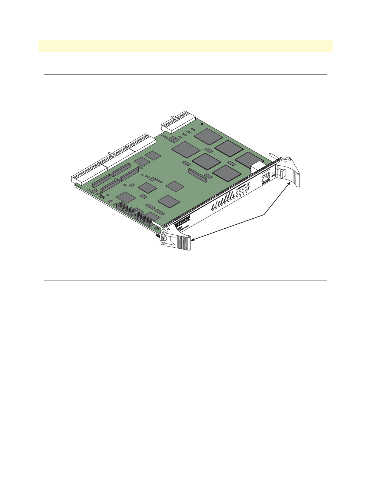
Board front panels
CompactPCI boards provide a front panel interface that is consistent with Eurocard packaging and compliant
with IEEE 1101.10 (EMC panels). Ejector/injector handles are used on the boards (see figure 9). Filler panels
do not require handles.
Injector/ejector
handles
Figure 9. Front panel—6U front-entry card
Transition Boards
There are two types of boards:
• Front-entry boards (described in section “Board front panels”)
• Rear-entry boards for rear-panel I/O
The front-entry boards may route I/O through the backplane. Backplanes that enable rear I/O are called often
midplanes because the legs of the backplane connector’s pins stick through the board to become pins for rearpanel interconnections. An illustration of the front-entry board and rear-panel I/O board interface with the
backplane/midplane is shown in figure 10.
Board front panels 27
Page 28

Model 6476 User Guide 3 • System Architecture
Mid-plane
6U Transition module
READY
RS232 CONFIG
FRAME
WAN PORTS
ERROR
4
3
2
PMC
1
CALLS ACT
ETHERNET B
ETHERNET A
SYSTEM
ALARM
CPU FAIL
POWER
6U Front card
Figure 10. Front/rear boards and backplane interface
Rear-panel I/O boards are 6U in width and are 80mm in depth. The 4U chassis provides an 80mm transition
module section. This section provides eight 6U x 80mm slots for cPCI transition modules.
All front-entry board features (handles, keying, alignment pin, EMC, etc.) are also utilized on the rear-entry
boards. The rear-panel I/O transition boards are “in-line” with the front-entry boards. This means that the
front panels of rear-panel I/O transition boards are reversed (mirrored) from the front boards. The top handles
are on the bottom and vice versa. The slot keying holes and hole labels in both the card guides and front panels
are upside down compared to the front boards and card guides.
The same connector pin labeling sequence is used on the rear I/O transition boards as on the front boards,
with the position numbers going from bottom to top. This is a mirror image of the front board’s layout orientation. Using the same 1-for-1 pin mapping sequence eliminates confusion and I/O signal pin mapping problems. For example, pin A3 is the same on the front boards, on the rear I/O transition board, and on the
backplane.
Rear-panel I/O transition boards may have active components in some applications. Power can be applied
either through the I/O pins from the front board, or from the normal power and ground pins defined as part of
the J1/P1 and J2/P2 connector pin assignments.
Transition Boards 28
Page 29
Model 6476 User Guide 3 • System Architecture
Pin and socket connectors
The connection between boards and backplane is through a two-piece, 2 mm connector. Backplanes use male
(pin) connectors and plug-in boards use female (socket) connectors. This pin and socket connector offers
greater reliability, particularly when subject to shock, vibration, or temperature variations.
These pin and socket connectors provide:
• Faster propagation times
• Reduced reflection at the bus/connector interface
• Lower noise
• Better impedance matching
• Higher mechanical stability
The connector is a 235-pin device, arranged in 47 rows of 5 pins, with a total of 220 pins (15 pins are lost to
the keying area). The connector is shielded and devotes a large number of pins to ground. This reduces reflections, increases EMI immunity in noisy environments, and reduces ground bounce.
The fixed or male connector on the backplane is numbered P1-P5, starting at the bottom. The corresponding
female connectors on the 6U cards are numbered J1–J5 from the bottom up (see figure 11).
6U Card
110 Pins
Key Area
110 Pins
95 Pins
110 Pins
110 Pins
Key Area
J5
J4
J3
J2
J1
Optional sub-bus
e.g., CT H.110 Bus
PICMG Defined I/O
or User Defined I/O
64-bit PCI Local Bus
and System Slot Cntr.
or PICMG Defined I/O
or User Defined I/O
32-bit PCI Local Bus
Figure 11. J1 through J5 connectors on the 6U card
3U and 6U cards use a single 220 pin connector for all power, ground, and all 32- and 64-bit PCI signals. This
connector consists of two halves—the lower half (110 pins) is called J1/P1 and the upper half (also 110 pins) is
called J2/P2. Twenty pins are reserved for future use. The connector is divided in J1/P1, a 25-row connector
that includes voltage keying, and J2/P2, a 22-row connector without keying. The 4U card can have up to four
additional connectors with a total of 315 pins, which can be used for a variety of purposes.
Pin and socket connectors 29
Page 30

Model 6476 User Guide 3 • System Architecture
A system CPU uses J1 and J2, but 32-bit peripherals cards only need to use J1 for full CompactPCI functionality. J3 through J5 on 4U cards can be user-defined I/O. Optional buses, such as the CT H.110 bus, use the
J4 position.
J1/P1 & J2/P2 connectors
The CompactPCI bus spans the J1/P1 & J2/P2 connectors, with 32-bit PCI implemented on J1/P1 and full
64-bit PCI implemented on J2/P2 on the Model 6476 Midplane. J1/P1 is always devoted to 32-bit PCI in
CompactPCI systems, however, use of J2/P2 for 64-bit PCI can be optional. For instance, in a 3U system, J2/
P2 may be defined for user I/O, or sub-buses like the CT H.110 bus. J2 is always used on system slot boards to
provide arbitration and clock signals for peripheral boards.
J3/P3 through J5/P5 connector
J3/P3 through J5/P5 connectors, available only in 4U systems, are generally defined for user I/O. However,
sub-bus interconnects (for example, CT H.110 bus) can be configured on the J4/P4 connector.
Reserved Pins
There are bused and non-bused reserved pins as noted below:
• The BRSVPxxx signals SHALL be bused between connectors and are reserved for future CompactPCI def-
inition.
• The RSV signals are non-bused signals that SHALL be reserved for future CompactPCI definition.
Power Pins
The 4U Model 6476 Backplane/Midplane has a customer-selectable signaling environment. All connectors on
the 4U Model 6476 Backplane/Midplane provide pins for +5V, +3.3V, +12V and -12V operating power. In
addition, there are power pins labeled +V(I/O). The V(I/O) power pins on the connector are used to power the
buffers on the peripheral boards, allowing a card to be designed to work in either interface. CompactPCI supports this dual-interface scheme by utilizing backplane connector keying.
Backplane Architecture
Patton Electronics Company, 4U Model 6476 Backplane/Midplane provides eight 6U board locations with
20.32 mm (0.8 inch) board center-to-center spacing. The 6U cards are stacked horizontally in the 4U model,
however, the special design provides vertical convection cooling with the installed 6470-FT plug-in fan tray
module.
There are also eight 3U x 160mm slots on the front right side, called the “Power Bay”, to mount Patton Power
Supply Modules configured for external DC or AC power input, or other cPCI compatible power modules.
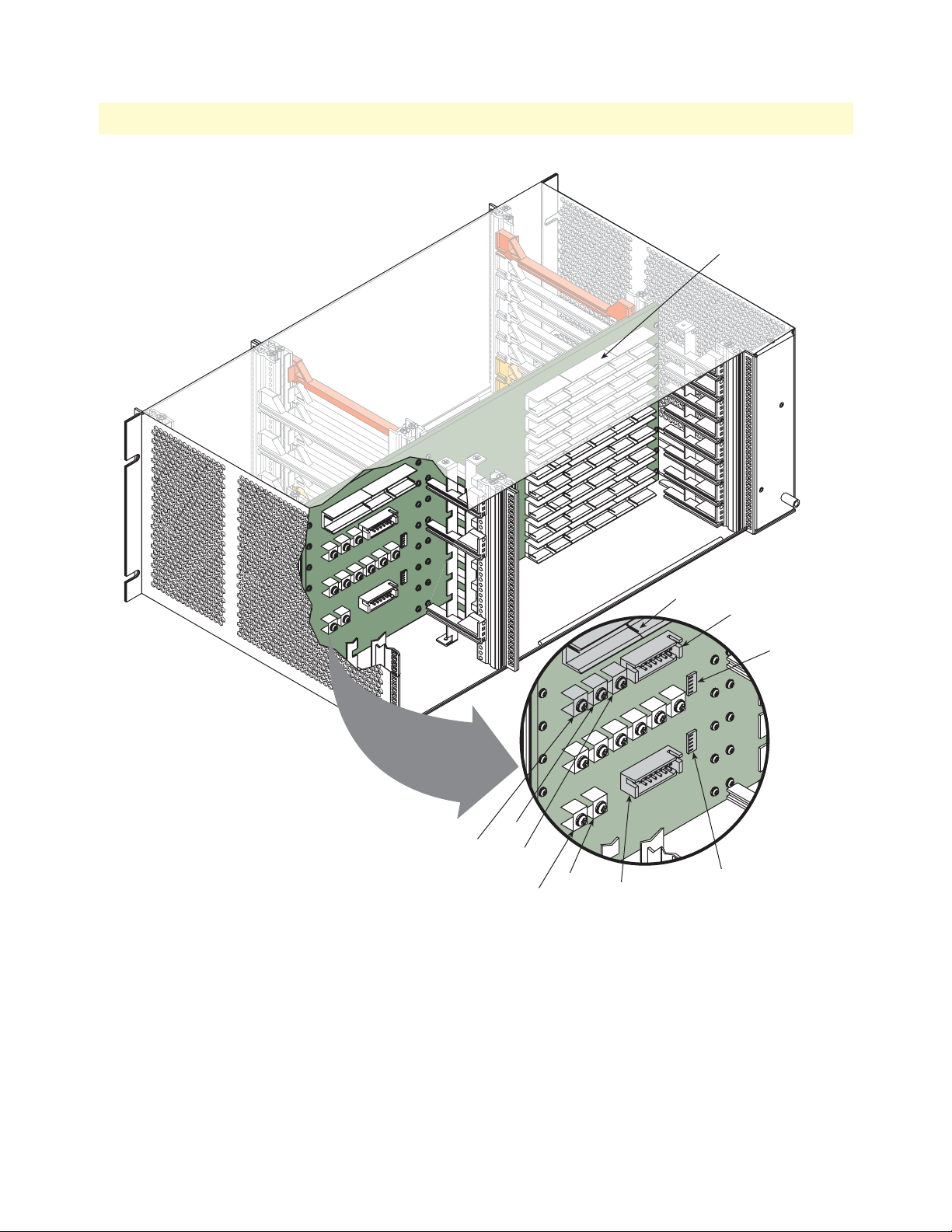
A rear view of the 4U Model 6476 is shown in figure 12.
Backplane Architecture 30
Page 31
Model 6476 User Guide 3 • System Architecture
8 6U slots—horizontal orientation
Alarm
J3 (+5v)
J2 (VIO)
J1 (+3.3v)
J5 (FG)
J4 (SG)
Power connector
module slot
Address (SGA) DIP switch S2
Power connector
(for Power Entry Module
DC or AC)
Fabric Slot
Geographic
Address (FSGA)
DIP switch S3
Shelf Geographic
Figure 12. Rear view of chassis showing the midplane/backplane
There are two user-configurable straps and a DIP switch located in the rear 3U area of the chassis:
• VIO signaling—This strap (using J3, J4, and J5) sets the V I/O signaling voltage to 3.3 or 5 VDC. For all
ForeFront applications, this should be set to 3.3v. Do not change it from this setting.
• Frame ground/signal ground—This strap (using J1 and J2) allows the user to electrically connect frame
ground (FG) to signal ground (SG). By default, these signals are electrically isolated. Patton Electronics recommends that this configuration be maintained. However, in certain specific circumstances, users may wish
to connect these two potentials by installing a jumper between J4 and J5.
Backplane Architecture 31
Page 32

Model 6476 User Guide 3 • System Architecture
• Shelf Geographic Address (SGA)—S2 is a DIP switch that enables the user to configure the shelf enumera-
tion feature, used for multi-shelf CompactPCI systems. The SGA effectively becomes a chassis identification code, which is used to uniquely identify the chassis in a multi-chassis environment. This is currently
not used in most ForeFront applications, as most cards/devices are uniquely identified by an IP address,
which is manually configured for each device in the system.
• Fabric Slot Geographical Address (FSGA)—S3 is a DIP switch that enables the user to configure for a
redundant shelf enumeration feature, used in multi-shelf CompactPCI systems. For redundancy, the user
should configure this switch to the same address as that used for S2.
Backplane power distribution
Power is distributed in a CompactPCI system via the backplane. The backplane provides standard direct current (DC) supply voltages as specified in table 7 below
Table 7. Power specifications
Mnemonic Description Nominal Value Tolerance
5 V +5 VDC 5.0 V ±5%
3.3 V +3.3 VDC 3.3 V ±5%
+12 V +12 VDC 12.0 V ±5%
-12 V -12 VDC -12.0 V ±5%
GND Ground
External power connections
The chassis provides a rear DC interface panel with -48V DC power interfaces for N+N power operation and
dual ground lugs, as shown in figure 5 on page 20. The connectors are described in table 8.
Table 8. Description of rear interface panel connectors
Item Description
-48 VDC power terminal
AC power interface The AC power interface accepts 115 - 230 VAC (50–60 Hz), 5 amp maximum
Ground lugs The dual frame ground lugs must be used to connect the chassis to earth ground on
DC rear-entry module accepts 36–75 VDC at 7.0 A max input via Phoenix connector. Polarity should be applied as marked (negative—top position, positive—bottom position). Each connector is independent and designed to power one 3U
power suppply module. There are three connectors provided for N+N power operation.
(IEC 320 connector).
DC interfaces. Failure to do this will cause excessive RF emissions and could possibly create a safety hazard. The double ground lug meets NEBS and will accept
Amp part # 606209-1. NEBS requires a double lug on DC chassis to ensure that
the ground connection will not rotate and become loose.
Backplane power distribution 32
Page 33

Model 6476 User Guide 3 • System Architecture
.
The dual frame ground lugs on DC interfaces must be used to connect the chassis to earth ground. Failure to do this will cause excessive RF emissions and
WARNING
could possibly create a safety hazard.
Hot-Swap Capability
Hot-swapping is the capability of removing and replacing components without turning off the system. Hotswap capability is becoming increasingly important in systems requiring continuous operation at some level.
Because boot times of many popular operating systems are long, the hot-swap capability is crucial for high-end
PC servers, and even more so for telecommunication systems, such as base stations, where board-level
exchanges must be made without any downtime. CompactPCI supports dynamic configuration to allow hot
removal/insertion of boards without interrupting backplane transactions or disturbing DC voltages in the
power system.
The hot-swap feature is implemented on the CPCI boards, not on the backplane. The backplane remains passive. Therefore, CompactPCI boards either are or are not hot-swappable.
Signal lines must be precharged to 1V before being plugged into the backplane to maintain ongoing bus transactions. Also, power must be ramped up or down in a controlled manner to allow the power supply to adjust to
the change in load. The power supply, ground and signal pins on the connectors are staged to allow sequencing, so as to not disturb the operation of the surrounding boards in the bus. The three levels of sequencing are:
• Short pins for BD_SEL#
• Medium pins for signals
• Long pins for power/ground
The system uses two levels of sequencing so that power/ground is made first/broken last. The short pin
(BD_SEL#) connection is made only when the board is firmly seated, which signals the control circuitry to
power up any high-current devices. Conversely, BD_SEL# breaks first to provide early warning to the
control circuitry.
Hot-Swap Capability 33
Page 34

Chapter 4 Installation checklist
Chapter contents
4U quick set-up checklist.......................................................................................................................................35
Power cable installation ...................................................................................................................................36
Installing the power cables—AC unit ........................................................................................................36
Installing the power cables—DC unit .......................................................................................................36
Grounding the Model 6476—AC and DC units ......................................................................................37
Changing the VI/O configuration jumper .......................................................................................................37
Optional Frame Ground/Signal Ground Connect ..........................................................................................37
34
Page 35

Model 6476 User Guide 4 • Installation checklist
4U quick set-up checklist
The Model 6476 Mid-plane & Chassis can be easily configured according to your system requirements. Due to
the broad application possibilities, the following checklist is provided as a quick set-up guideline.
1. Connect frame ground/signal ground (FG/SG)—You may opt to connect the FG/SG for EMC consider-
ations and noise reduction, via power lugs, located at the rear, right-side of the backplane. The factory
default is “no connect”.
2. Assign shelf address—For multi-shelf systems, each sub-rack bus segment can be assigned a shelf address
via the S2 and S3 DIP switches, located at the rear, left-side of the backplane (see section “Backplane
Architecture” on page 30).
3. Install 4U chassis on rack—the chassis front mounting flanges should be securely fastened to the rack
with screws.
4. Install power supply modules—For N+1 power operation, install up to three Patton power supply mod-
ules at the front of the chassis.
5. Install cards—Plug the system application card(s) in the 6U slot(s) at the front of the 4U chassis. Plug
alarm card in the left-hand slot at the back of the chassis, and plug transition cards in remaining slots, if
needed.
The interconnecting cables shall be acceptable for external use
and shall be rated for the proper application with respect to voltage, current, anticipated temperature, flammability, and
CAUTION
mechanical serviceability.
6. Wire rear panel for power.
Due to possible injuries to people and severe damage to objects caused by
electric shock, always wire for power as the last step.
WARNING
4U quick set-up checklist 35
Page 36

Model 6476 User Guide 4 • Installation checklist
Power cable installation
This section describes installing the power and ground cables.
Installing the power cables—AC unit
This section describes installing the power cables into the IEC-320 connectors on the Model 6476 power supply. Do not connect the remaining end of the power cables to the power outlet at this time. Do the following:
1. Install a power cable into an IEC-320 connector (see figure 13). The AC main socket outlet shall be within
3 meters of the equipment and shall be easily accessible.
AC power module
Grounding
studs
Figure 13. IEC-320 connector and grounding stud locations
To avoid the risk of injury from electric shock, the power cords connected to
the IEC-320 connectors must be grounded power cords.
WARNING
Power
switch
IEC-320
connector
Power cord
retainer clip
2. Rotate the power cable retainer clip (see figure 13) so it secures the power cable plug in the IEC-320 con-
nector.
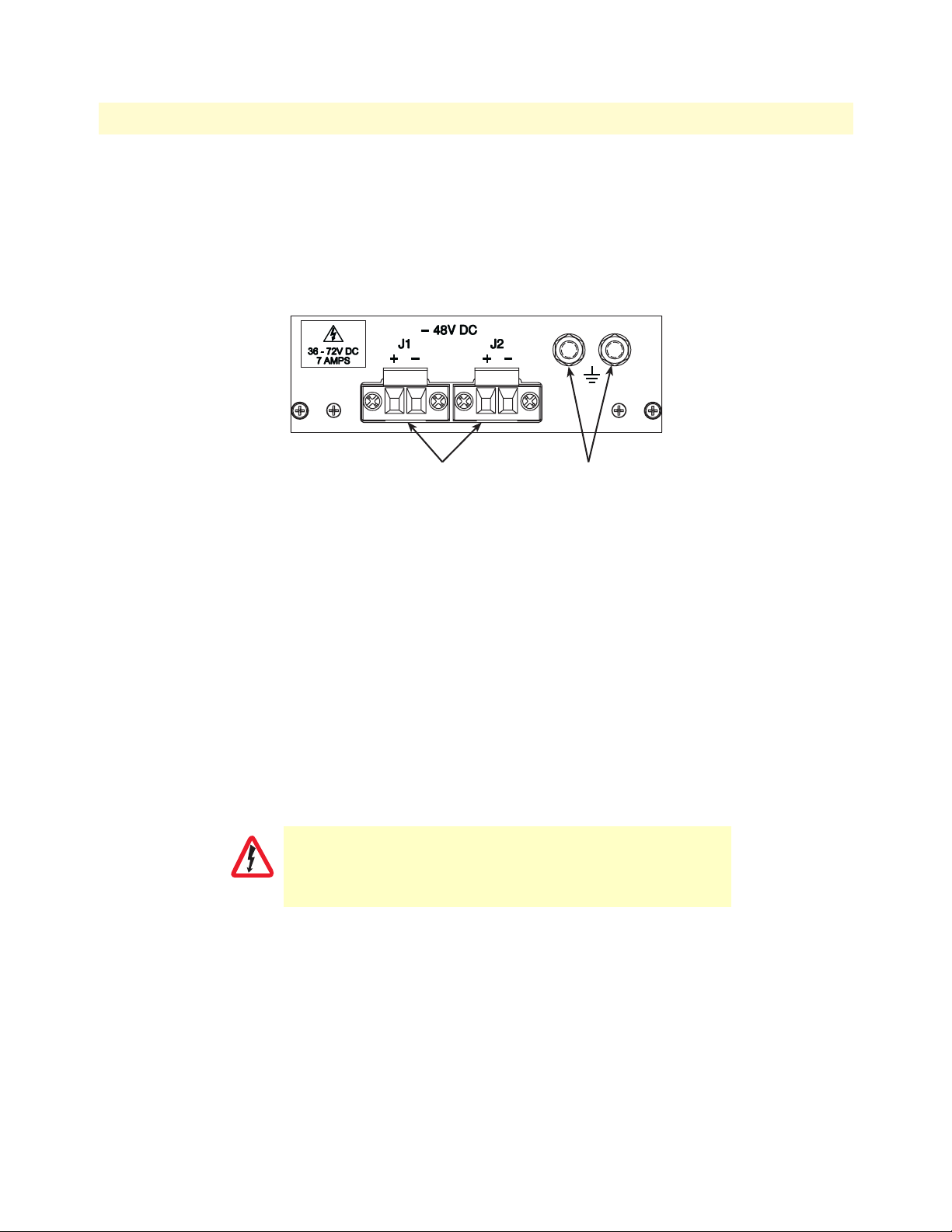
Installing the power cables—DC unit
This section describes installing the power cables into the DC power input module. Do not connect the
remaining end of the power cables to the DC power source at this time. The Model 6476 DC power supply
module comes with two power input terminal blocks (J1 and J2). The Model 6476 can draw power from
sources connected to either of these terminal blocks (inputs are diode-ORed and combined to provide for
redundant power input). Although the power supply module is designed to operate normally with one power
source, users may want to connect two independent power sources, one to each terminal block, to provide
uninterrupted operation in the event of one source failure.
Use AWG 18 copper conductors for the DC supply.
CAUTION
1. Connect the earth ground of the DC source to the grounding stud on the Model 6476 chassis as described
in section “Grounding the Model 6476—AC and DC units”.
4U quick set-up checklist 36
Page 37
Model 6476 User Guide 4 • Installation checklist
2. Strip back the insulation on each of the supply wires approximately 1/4 inch.
3. Insert the stripped end of the positive lead into the “+DC input” of the terminal block. Tighten the screw
until the power lead is firmly fastened. Repeat the procedure for the negative lead, using the “-DC input”
of the terminal block. Make sure that there is no exposed wire.
DC power module
DC power
entry connectors
Figure 14. DC connector, -DC and +DC input view
Grounding
studs
4. Repeat steps 1 through 3 to install the remaining DC power connection.
Grounding the Model 6476—AC and DC units
Do the following:
1. Assemble a ground wire using #10 AWG wire with green-colored insulation and two ring terminals. Make
the wire long enough to reach one of the following ground sources:
– The building ground rod (generally located at the site’s main service entrance)
– A sprinkler system pipe
– A cold-water pipe
– Building structural steel
To avoid the risk of personal injury, the distance between ground and the
equipment rack must not exceed the distance specified in either local electrical
codes or the National Electrical Code.
WARNING
2. Install the ground wire between the grounding studs (see figure 13 on page 36 for AC power entry, or
figure 14 on page 37 for DC power entry) and the grounding source.
Changing the VI/O configuration jumper
The Model 6476 VI/O is factory configured for 3.3V. Do not change this setting when using ForeFront cards.
Optional Frame Ground/Signal Ground Connect
There are two headers, J4 and J5, located in the power bay area (see figure 12 on page 31). J4 corresponds to
signal ground (SG) and J5 corresponds to frame ground (FG). These two headers provide an option to connect
4U quick set-up checklist 37
Page 38

Model 6476 User Guide 4 • Installation checklist
FG and SG. The factory default is for FG and SG to not be connected. Depending on the environment, you
can opt to connect the FG/SG for EMC considerations and noise reduction.
To connect FG to SG, do the following:
1. Locate J4 and J5 at the bottom of the power bay area (see figure 12 on page 31).
2. Use a Phillips screwdriver to loosen the screws on both headers.
3. Connect a jumper between J4 and J5 (see figure 15), then secure it with the Phillips head screws.
FG SG
J5 J4
Figure 15. Frame ground connected to signal ground
4U quick set-up checklist 38
Page 39

Chapter 5 Maintenance
Chapter contents
Preventive Maintenance.........................................................................................................................................40
Cleaning the fan filter .....................................................................................................................................40
Troubleshooting....................................................................................................................................................40
System won’t power up ...................................................................................................................................40
39
Page 40

Model 6476 User Guide 5 • Maintenance
Preventive Maintenance
Cleaning the fan filter
Periodically clean the filter on the Fan Tray Assembly. The frequency of cleaning depends on the environmental
conditions of where your equipment is located. Clean filter with a mild detergent and water, then air-dry, or
you can use compressed air. It should be completely dry before reuse.
Spare filters (part no. 6470-AF-6) are available from Patton Electronics Company.
Troubleshooting
System won’t power up
If the green LED on the power supply module does not light up, you should: remove the power supply module
from the chassis, then plug it back in, making sure it is seated properly. If the green LED still does not illuminae, verify that the polarity is wired correctly at the back of the chassis.
If the green LED lights up on the power supply module, but the system still isn’t powering-up, then the module may be faulty and should be returned to the manufacturer.
Preventive Maintenance 40
Page 41

Chapter 6 Contacting Patton for assistance
Chapter contents
Introduction..........................................................................................................................................................42
Contact information..............................................................................................................................................42
Patton support headquarters in the USA .........................................................................................................42
Alternate Patton support for Europe, Middle East, and Africa (EMEA) ..........................................................42
Warranty Service and Returned Merchandise Authorizations (RMAs)...................................................................42
Warranty coverage ..........................................................................................................................................42
Out-of-warranty service .............................................................................................................................43
Returns for credit ......................................................................................................................................43
Return for credit policy .............................................................................................................................43
RMA numbers ................................................................................................................................................43
Shipping instructions ................................................................................................................................43
41
Page 42

Model 6476 User Guide 6 • Contacting Patton for assistance
Introduction
This chapter contains the following information:
• “Contact information”—describes how to contact Patton technical support for assistance.
• “Warranty Service and Returned Merchandise Authorizations (RMAs)”—contains information about the
RAS warranty and obtaining a return merchandise authorization (RMA).
Contact information
Patton Electronics offers a wide array of free technical services. If you have questions about any of our other
products we recommend you begin your search for answers by using our technical knowledge base. Here, we
have gathered together many of the more commonly asked questions and compiled them into a searchable
database to help you quickly solve your problems.
Patton support headquarters in the USA
• Online support—available at http://www.patton.com
• E-mail support—e-mail sent to support@patton.com will be answered within 1 business day
• Telephone support—standard telephone support is available 5 days a week, from 8:00am to 5:00pm EST
(1300 to 2200 UTC/GMT)—by calling +1 (301) 975-1007
• Fax—+1 (253) 663-5693
Alternate Patton support for Europe, Middle East, and Africa (EMEA)
• Online support—available at http://www.patton-inalp.com
• E-mail support—email sent to support@patton-inalp.com will be answered within 1 day
• Telephone support—standard telephone support is available five days a week—from 8:00 am to 5:00 pm
CET (0900 to 1800 UTC/GMT)—by calling +41 (0)31 985 25 55
• Fax—+41 (0)31 985 25 26
Warranty Service and Returned Merchandise Authorizations (RMAs)
Patton Electronics is an ISO-9001 certified manufacturer and our products are carefully tested before shipment. All of our products are backed by a comprehensive warranty program.
Note If you purchased your equipment from a Patton Electronics reseller, ask your
reseller how you should proceed with warranty service. It is often more convenient for you to work with your local reseller to obtain a replacement. Patton services our products no matter how you acquired them.
Warranty coverage
Our products are under warranty to be free from defects, and we will, at our option, repair or replace the product should it fail within one year from the first date of shipment. Our warranty is limited to defects in workmanship or materials, and does not cover customer damage, lightning or power surge damage, abuse, or
unauthorized modification.
Introduction 42
Page 43

Model 6476 User Guide 6 • Contacting Patton for assistance
Out-of-warranty service
Patton services what we sell, no matter how you acquired it, including malfunctioning products that are no
longer under warranty. Our products have a flat fee for repairs. Units damaged by lightning or other catastrophes may require replacement.
Returns for credit
Customer satisfaction is important to us, therefore any product may be returned with authorization within 30
days from the shipment date for a full credit of the purchase price. If you have ordered the wrong equipment or
you are dissatisfied in any way, please contact us to request an RMA number to accept your return. Patton is
not responsible for equipment returned without a Return Authorization.
Return for credit policy
• Less than 30 days: No Charge. Your credit will be issued upon receipt and inspection of the equipment.
• 30 to 60 days: We will add a 20% restocking charge (crediting your account with 80% of the purchase
price).
• Over 60 days: Products will be accepted for repairs only.
RMA numbers
RMA numbers are required for all product returns. You can obtain an RMA by doing one of the following:
• Completing a request on the RMA Request page in the Support section at www.patton.com
• By calling +1 (301) 975-1000 and speaking to a Technical Support Engineer
• By sending an e-mail to returns@patton.com
All returned units must have the RMA number clearly visible on the outside of the shipping container. Please
use the original packing material that the device came in or pack the unit securely to avoid damage during
shipping.
Shipping instructions
The RMA number should be clearly visible on the address label. Our shipping address is as follows:
Patton Electronics Company
RMA#: xxxx
7622 Rickenbacker Dr.
Gaithersburg, MD 20879-4773 USA
Patton will ship the equipment back to you in the same manner you ship it to us. Patton will pay the return
shipping costs.
Warranty Service and Returned Merchandise Authorizations (RMAs) 43
Page 44

Appendix A Compliance information
Chapter contents
Radio and TV Interference (FCC Part 15) ............................................................................................................45
EC Declaration of Conformity ..............................................................................................................................45
FCC Part 68 (ACTA) Statement ...........................................................................................................................45
Industry Canada Notice ........................................................................................................................................46
44
Page 45

Model 6476 User Guide A • Compliance information
Radio and TV Interference (FCC Part 15)
This equipment generates and uses radio frequency energy, and if not installed and used properly-that is, in
strict accordance with the manufacturer's instructions-may cause interference to radio and television reception.
This equipment has been tested and found to comply with the limits for a Class A computing device in accordance with the specifications in Subpart B of Part 15 of FCC rules, which are designed to provide reasonable
protection from such interference in a commercial installation. However, there is no guarantee that interference will not occur in a particular installation. If the equipment causes interference to radio or television reception, which can be determined by disconnecting the cables, try to correct the interference by one or more of
the following measures: moving the computing equipment away from the receiver, re-orienting the receiving
antenna, and/or plugging the receiving equipment into a different AC outlet (such that the computing equipment and receiver are on different branches).
In order to comply with UL60950 leakage current requirements, it
is recommended that the AC inputs be supplied from separate and
isolated sources.
IMPORTANT
EC Declaration of Conformity
We certify that the apparatus identified in this document conforms to the requirements of Council Directive
1999/5/EC on the approximation of the laws of the member states relating to Radio and Telecommunication
Terminal Equipment and the mutual recognition of their conformity.
The safety advice in the documentation accompanying this product shall be obeyed. The conformity to the
above directive is indicated by the CE sign on the device.
FCC Part 68 (ACTA) Statement
This equipment complies with Part 68 of FCC rules and the requirements adopted by ACTA. On the bottom side of
this equipment is a label that contains-among other information-a product identifier in the format US:
AAAEQ##TXXXX. If requested, this number must be provided to the telephone company.
The method used to connect this equipment to the premises wiring and telephone network must comply with the
applicable FCC Part 68 rules and requirements adopted by the ACTA.
If this equipment causes harm to the telephone network, the telephone company will notify you in advance that temporary discontinuance of service may be required. But if advance notice isn't practical, the telephone company will notify
the customer as soon as possible. Also, you will be advised of your right to file a complaint with the FCC if you believe
it is necessary.
The telephone company may make changes in its facilities, equipment, operations or procedures that could affect the
operation of the equipment. If this happens the telephone company will provide advance notice in order for you to
make necessary modifications to maintain uninterrupted service.
If trouble is experienced with this equipment, for repair or warranty information, please contact our company. If the
equipment is causing harm to the telephone network, the telephone company may request that you disconnect the
equipment until the problem is resolved.
Connection to party line service is subject to state tariffs. Contact the state public utility commission, public service
commission or corporation commission for information.
Radio and TV Interference (FCC Part 15) 45
Page 46

Model 6476 User Guide A • Compliance information
Industry Canada Notice
This equipment meets the applicable Industry Canada Terminal Equipment Technical Specifications. This is confirmed
by the registration number. The abbreviation, IC, before the registration number signifies that registration was performed based on a Declaration of Conformity indicating that Industry Canada technical specifications were met. It does
not imply that Industry Canada approved the equipment.
This Declaration of Conformity means that the equipment meets certain telecommunications network protective,
operational and safety requirements. The Department does not guarantee the equipment will operate to the user's satisfaction. Before installing this equipment, users should ensure that it is permissible to be connected to the facilities of the
local telecommunications company. The equipment must also be installed using an acceptable method of connection.
In some cases, the company's inside wiring associated with a single line individual service may be extended by means of
a certified connector assembly (telephone extension cord). The customer should be aware that compliance with the
above condition may not prevent degradation of service in some situations. Repairs to some certified equipment should
be made by an authorized maintenance facility designated by the supplier. Any repairs or alterations made by the user to
this equipment, or equipment malfunctions, may give the telecommunications company cause to request the user to
disconnect the equipment. Users should ensure for their own protection that the ground connections of the power utility, telephone lines and internal metallic water pipe system, are connected together. This protection may be particularly
important in rural areas.
Users should not attempt to establish or modify ground connections
themselves, instead they should contact the appropriate electric
inspection authority or electrician.
CAUTION
Industry Canada Notice 46
Page 47

Appendix B Glossary of Terms
Chapter contents
C....................................................................................48
CFM .......................................................................48
CSA ........................................................................48
CT ..........................................................................48
D....................................................................................48
Dual Redundant ......................................................48
E ....................................................................................48
ECTF ......................................................................48
EIA ..........................................................................48
EMC .......................................................................48
EMI ........................................................................48
EN ..........................................................................48
Enumeration ...........................................................48
ESD ........................................................................48
Eurocard .................................................................48
H ...................................................................................48
Hot-Swap ................................................................48
HP ..........................................................................48
I .....................................................................................49
IDE .........................................................................49
IEC .........................................................................49
IEEE .......................................................................49
IN/C .......................................................................49
ISA ..........................................................................49
K ...................................................................................49
Keying .................................................................... 49
N................................................................................... 49
N+1 Redundant ..................................................... 49
NEBS ..................................................................... 49
NP .......................................................................... 49
P.................................................................................... 49
PCI ......................................................................... 49
PCI SIG ................................................................. 49
PICMG .................................................................. 49
Platform ................................................................. 49
S.................................................................................... 49
SELV ...................................................................... 49
S-HAZ ................................................................... 49
Shroud .................................................................... 50
T ................................................................................... 50
TDM ...................................................................... 50
TNV ...................................................................... 50
U................................................................................... 50
U ............................................................................ 50
W .................................................................................. 50
Warm-Swap ............................................................ 50
47
Page 48

B • Glossary of Terms Model 6476 User Guide
C
CFM
Cubic feet per minute—A measurement of how much
air is moved through a fan.
CSA
Canadian Standards Association—Organization
which operates a listing service for electrical and electronic materials and equipment. It is the body that
establishes telephone equipment (and other) standards for use in Canada.
CT
Computer Telephony—is the adding of computer
intelligence to the making, receiving, and managing
of telephone calls.
D
Dual Redundant
An environment containing two power supplies, with
fault tolerance such that one power supply may fail
and the system will continue to operate.
E
EMI
Electromagnetic Interference—any electromagnetic
interference, periodic or random, narrow or broadband, which may have a disturbing influence on
devices exposed to it.
EN
European Norms—Prefix assigned to documents
adopted by the CE designating required standards
(for example, EN 60950 is the safety specification
(equivalent to UL 1950)).
Enumeration
The action taken by the Host to poll the configuration spaces of the PCI devices and allocate (deallocate) the necessary resources (memory and/or I/O
address space, interrupts, software drivers).
ESD
Electrostatic Discharge—Discharge of a static charge
on a surface or body through a conductive path to
ground. Can be damaging to integrated circuits.
Eurocard
A series of mechanical board form factor sizes for
rack-based systems.
H
ECTF
Enterprise Computer Telephony Forum—A nonprofit corporation formed to focus on the technical
challenges of interoperability among Computer Telephony Integration (CTI) products.
EIA
Electronics Industry Association—Trade organization of manufacturers which sets standards for use of
its member companies.
EMC
Electromagnetic Compatibility—Is the ability of
equipment or systems to be used in their intended
environment within designed efficiency levels without
causing or receiving degradation due to unintentional
EMI.
48 C
Hot-Swap
The capability of removing and replacing components
without turning off the system. Hot-swap capability is
increasingly important in systems used for applications such as telecommunications, which require that
the system be operational at some level continuously.
HP
Horizontal Positioning—A unit of measurement used
for the width of CPCI cards/modules. 1 HP = 0.2”
wide
Page 49

Model 6476 User Guide B • Glossary of Terms
I
IDE
Integrated Drive Electronics—a hard disk drive standard interface for PCs.
IEC
International Electrotechnical Committee
IEEE
Institute of Electrical and Electronics Engineers
IN/C
Insulation No Connect—required for safety agency
insulation requirements.
ISA
Industry Standard Architecture—A specification by
which Personal Computers (PCs) add boards.
K
NP
Not Populated—pins within connector that must not
be populated due to safety requirements.
P
PCI
Peripheral Component Interconnect. A specification
for defining between logic components. Typically
used for interconnecting high-speed, PC-compatible
chipset components. The PCI specification is issued
through the PCI Special Interest Group (PCI SIG).
PCI SIG
Peripheral Component Interconnect Special Interest
Group
PICMG
PCI Industrial Computers Manufacturers Group—a
consortium of industrial computer product vendors
who develop specifications for PCI-based systems and
boards for use in industrial computing applications.
Keying
A mechanical means of polarizing connectors in order
to prevent similar connectors from being mated. This
is necessary when 2 or more similar connectors must
be connected to a backplane which requires that the
board being connected is unique for a particular slot.
N
N+1 Redundant
An environment containing more than two power
supplies, where the power supplies typically current
share, with fault tolerance such that one power supply
may fail and the system will continue to operate.
NEBS
Network Equipment Building Standards—Defines a
rigid and extensive set of performance, quality, environmental and safety requirements developed by
Bellcore, the R&D and standards organization owned
by the seven regional Bell operating companies
(RBOC’s).
Platform
Describes the system environment, including the
backplane and related enclosure.
S
SELV
Safety Extra Low Voltage—a term generally defined
by the regulatory agencies as the highest voltage that
can be contacted by a person and not cause injury. It
is often specifically defined as 30 VAC or 42.4 VDC.
S-HAZ
Secondary Hazardous—any voltage within a system
that is greater than 60VDC (42.4VAC-peak), NOT
meeting the requirements for a LIMITED CURRENT CIRCUIT, or for a TNV CIRCUIT. Typical
ringing voltage is considered SECONDARY HAZARDOUS unless it is current limited. Raw ringing is
considered SECONDARY HAZARDOUS. (Refer to
IEC950 or PICMG 2.5 R1.0 CompactPCI‚ Computer Telephony Specification for information.)
I 49
Page 50

B • Glossary of Terms Model 6476 User Guide
Shroud
A male connector body designed to fit over the
extended tails of a long tail connector which allows a
female connector to be mated from the rear side for
midplane or rear I/O applications.
T
TDM
Time Division Multiplex—A technique for transmitting a number of separate data, voice and/or video signals simultaneously over one communications
medium by quickly interleaving a piece of each signal
one after another.
TNV
Telephone Network Voltages—any voltage present on
the telephone network side of the isolation device on
any device (for example, board) that connects to the
telephone network.
U
U
An EIA unit of measurement equal to 1.75 in.
(4.45 cm) for equipment racks.
W
Warm-Swap
An environment supporting removal and insertion of
power supplies while under power, wherein the power
supply is disabled during insertion and removal,
avoiding the need for the connectors to make and
break high current connections while under load.
50 T
 Loading...