

Page 1
USER
MANUAL
Model 6103
3U ForeFront
Alarm Card
An ISO-9001
Certified Company
Part# 07M6103
Doc# 123011U Rev. B
Revised 11/11/04
SALES OFFICE
(301) 975-1000
TECHNICAL SUPPORT
(301) 975-1007
Page 2

CONTENTS
1.0 Warranty Information ................................................................. 3
1.1 Radio and TV Interference.......................................................... 3
1.2 CE Notice.................................................................................... 3
1.3 Service........................................................................................ 4
1.4 Trademark Acknowledgements .................................................. 4
2.0 General Information.................................................................. 5
2.1 Product Features ........................................................................ 5
2.2 Description.................................................................................. 5
3.0 Operation................................................................................... 6
3.1 Rear Panel Features................................................................... 6
Alarm LED information................................................................ 6
Alarm types.............................................................................. 6
Alarm severity.......................................................................... 7
Alarm Relays (Form-C Outputs).............................................. 7
Alarm Cut Off Switch............................................................... 7
Fan monitor ............................................................................. 7
Temperature Monitor............................................................... 8
Power Supply Monitor ............................................................. 8
3.2 Alarm Conditions......................................................................... 8
Fan Tray Alarm Conditions ......................................................... 8
Temperature Alarm Conditions................................................... 9
Power Supply Alarm Conditions.................................................. 9
System Alarm Conditions............................................................ 9
3.3 Alarm Indications ........................................................................ 9
Fan Alarm Indications ................................................................. 9
Temperature Alarm Indications................................................. 10
Power Supply Alarm Indications ............................................... 10
System Alarms.......................................................................... 10
A Form-C Connector Pin Assignments.................................... 12
2
Page 3

1.0 WARRANTY INFORMATION
Patton Electronics
defects, and will—at our option—repair or replace the product should it f ail
within one year from the first date of shipment. This warranty is limited to
defects in workmanship or materials, and does not cover customer damage, abuse or unauthorized modification. If this product fails or does not
perform as warranted, your sole recourse shall be repair or replacement
as described above. Under no condition shall Patton Electronics be liable
for any damages incurred by the use of this product. These damages
include, but are not limited to , the following: lost profits, lost sa vings and
incidental or consequential damages arising from the use of or inability to
use this product. Patton Electronics specifically disclaims all other warranties, expressed or implied, and the installation or use of this product shall
be deemed an acceptance of these terms by the user.
1.1 RADIO AND TV INTERFERENCE
The Model 6103 generates and uses radio frequency energy, and if not
installed and used properly—that is, in strict accordance with the manufacturer's instructions—may cause interference to radio and television reception. The Model 6103 has been tested and found to comply with the limits
for a Class A computing device in accordance with the specifications in
Subpart B of Part 15 of FCC rules, which are designed to provide reasonable protection from such interference in a commercial installation. However, there is no guarantee that interference will not occur in a particular
installation. If the Model 6103 does cause interference to radio or television reception, which can be determined by turning the power off or disconnecting the RS-232 interface, the user is encouraged to try to correct
the interference by one of the f ollowing measures: moving the computing
equipment away from the receiver, re-orienting the receiving antenna and/
or plugging the receiving equipment into a different AC outlet (such that
the computing equipment and receiver are on different branches).
warrants all Model 6103 components to be free from
1.2 CE NOTICE
The CE symbol on your Patton Electronics equipment indicates that it is in
compliance with the Electromagnetic Compatibility (EMC) directive and
the Low Voltage Directive (LVD) of the Union European (EU). A Certificate
of Compliance is available by contacting Patton Technical Support.
3
Page 4

1.3 SERVICE
All warranty and non-warranty repairs must be returned freight prepaid
and insured to Patton Electronics. All returns must have a Return Materials Authorization number on the outside of the shipping container. This
number may be obtained from Patton Electronics Technical Service at:.
Tel:
(301) 975-1007
E-mail:
URL:
support@patton.com
www.patton.com
Note
Packages received without an RMA number will not
be accepted.
Patton Electronics' technical staff is also av ailable to ans wer any questions
that might arise concerning the installation or use of your Model 6103.
Technical Service hours:
8AM
to
5PM EST, Monday
through
Friday
.
1.4 TRADEMARK ACKNOWLEDGEMENTS
The term
ForeF ront
is a registered trademark of Patton Electronics Co . in
the United States and other countries.
4
Page 5

2.0 GENERAL INFORMATION
Thank you for your purchase of this
product has been thoroughly tested and is warranted for One Year parts
and labor. If you have questions regarding the installation or use of this
product, please contact
(301) 975-1007
2.1 PRODUCT FEATURES
• Fits in Patton’s Model 6276, Model 6476, and Model 6676 ForeFront
chassis assemblies
• Monitors chassis fan speed
• Monitors chassis power supply status
• Monitors chassis temperature
• Receives and indicates system alarms
• Six LED alarm indicators
• Alarm relay presented on Form-C (DB-9)
• Alarm cut-off switch
• Auto-interlock mechanism for reliable connections to ForeFront chassis
2.2 DESCRIPTION
The
Model 6103 Forefront Alarm Card
Model 6276, Model 6476, and Model 6676 Forefront Chassis Assemblies. The Model 6103 continuously monitors the chassis fan tray
tachometer signals, the power supplies, and the chassis temperature for
alarm conditions. The Model 6103 can also receive system alarms from
a 3096 that is designated as “proxy” by the user. Upon reception of an
alarm condition the Model 6103 will illuminate the appropriate rear panel
indicator LED’s and will complete the appropriate circuits through the
Form-C output. When the alarm conditions have been cleared the Model
6103 will reset the LED’s and Form-C output and return to normal operating condition.
.
Patton Electronics Technical Support
Patton Electronics
is intended for use in Patton’s
product. This
at
5
Page 6

3.0 OPERATION
Upon plugging the Model 6103 into the chassis, the unit will perform an
LED self-test. After successful completion of this self-test the Model 6103
will be in normal operating mode and will monitor the fan tachometers, the
power supply, and the temperature in the chassis on a continual basis.
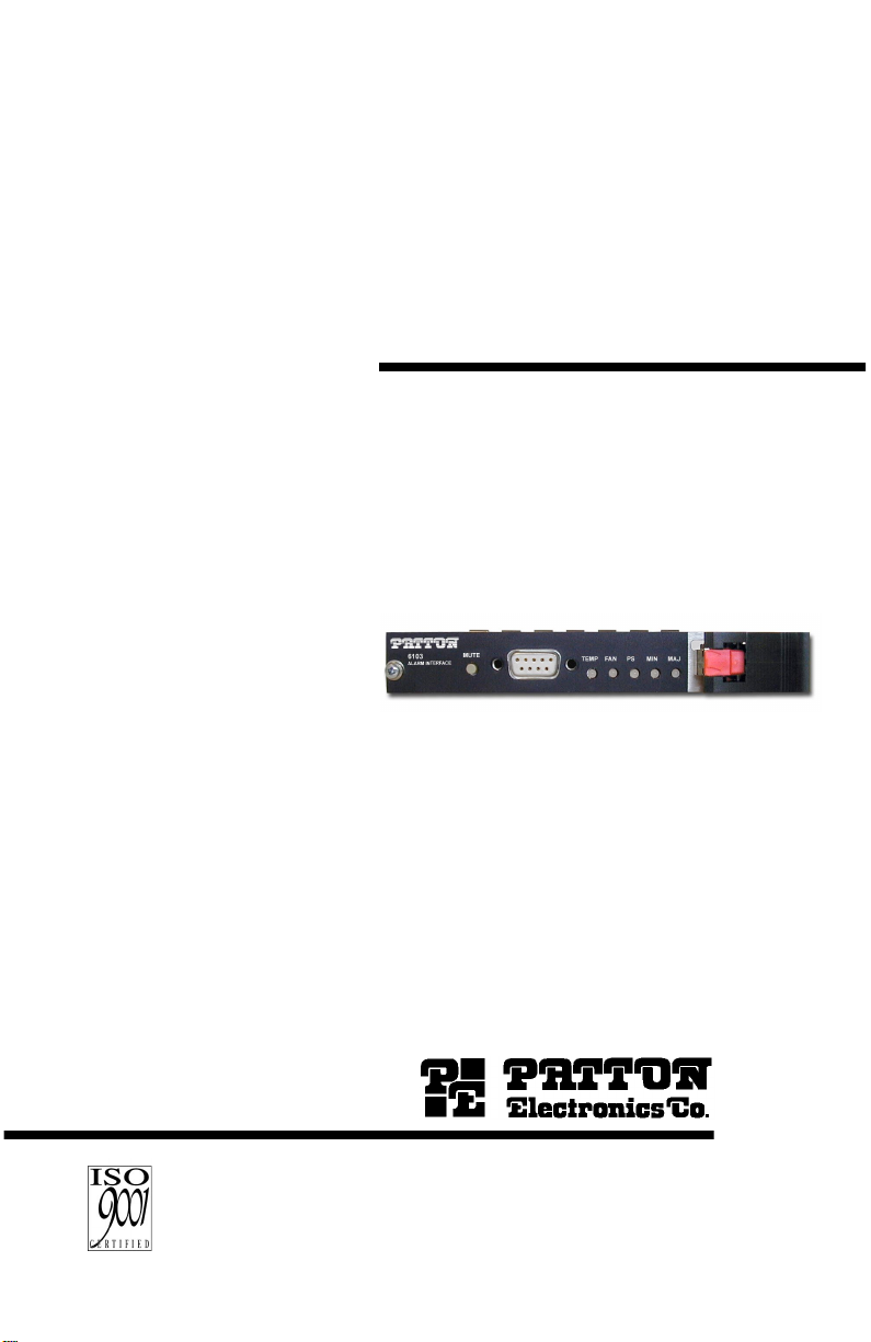
3.1 REAR PANEL FEATURES
The Model 6103 features five rear panel bi-color LEDs that display the
current state of the ForeFront system. Figure 1 shows the rear panel
location of each LED. Following Figure 1 is a description of each LED’ s
function. If an alarm condition occurs, the
illuminate yellow.
severity of the alarm condition.
MIN
or
MAJ
will also illuminate depending on the
TEMP, FAN
, or PS LEDs will
Figure 1.
Rear panel LEDs, ACO switch, and Alarm Relay port locations
Alarm LED information
The Model 6103 alarm card monitors the following items: fan tray, power
supply, and chassis temperature.
Alarm types
•
TEMP indicator
green when there is no temperature alarm.
•
F AN indicator
green when there is no fan tachometer alarm.
•
PS indicator
green when there is no power supply alarm.
—Glows yellow in the case of a temperature alarm or
—Glows yellow in the case of a f an tachometer alarm or
—Glows yellow in the case of a power supply alarm or
6
Page 7

Alarm severity
•
MIN indicator
green when there is no minor alarm condition.
•
MAJ indicator
green when there is no major alarm condition.
—Glows yellow in the case of a minor alarm condition or
—Glows red in the case of a major alarm condition or
Indicator Function
LED color under normal & alarm conditions
Normal Alarm
TEMP (Temperature) status Green Yellow
FAN status Green Yellow
PS (Power Supply) status Green Yellow
MIN (Minor) Alarm status Green Yellow
MAJ (Major) Alarm status Green Red
Alarm Relays (Form-C Outputs)
The Model 6103 is equipped with two Form-C relay outputs presented on
a DB-9 connector located on the rear panel (see Figure 1 on page 6). In
the event of an alarm, the Model 6103 will complete one of two circuits
through this Form-C connector.
A Form-C relay has three contacts: normally open (N.O .), normally closed
(N.C.), or a common contact. When no alarm is issued, the Form-C relay
will connect common to N.C. In the e vent of an alarm, the common contact
will connect to the normally-open (N.O.) contact. If it is a minor alarm, the
Model 6103 will connect pin 5 to pin 9. In the event of a major alarm, the
Model 6103 will connect pin 2 to pin 6.
Note
Contact rated load is 12 amps at 24 VDC.
Alarm Cut Off Switch
The Model 6103 is equipped with an alarm cut-off switch (ACO) on the
rear panel as shown in Figure 1 on page 6. If an alarm occurs and you
want to temporarily turn off the form-C output, press the ACO button to
do so. To return the relays to the alarm condition, press the ACO button a
second time.
Fan monitor
The Model 6103 monitors the fan tray tachometer signals. If a fan tray
alarm signal is detected, the alarm card will illuminate the FAN LED. The
Model 6103 will also illuminate either the MIN or the MAJ LED depending on the severity of the alarm condition.
7
Page 8

Temperature Monitor
The Model 6103 monitors the temperature inside the chassis. If a temperature alarm is detected, the alarm card will illuminate the TEMP LED
and the MAJ LED.
Power Supply Monitor
The Model 6103 monitors the chassis power supplies. If a power supply
alarm is detected, the alarm card will illuminate the PS LED. The Model
6103 will also illuminate either the MIN or the MAJ LED depending on
the severity of the alarm condition.
3.2 ALARM CONDITIONS
The following section describes the conditions necessary to set an alarm
in the Model 6103. Fan, Temperature, and power alarm conditions are
internally set. System alarm conditions are set in the Patton Model 3096.
Fan Tray Alarm Conditions
The Model 6103 monitors the tachometer signals from the fans in the chassis. The following describes the conditions necessary to set a fan alarm.
Alarm Condition
Fan Minor Alarm One fan has dropped to 1/2 speed
Fan Major Alarm • Two or more fans have dropped to 1/2 speed
• One or more fans have dropped to 3/8 speed
8
Page 9

Temperature Alarm Conditions
The Model 6103 monitors the temperature in the chassis through an onboard temperature sensor. The following describes the conditions necessary to set a temperature alarm.
Alarm Condition
Temperature Major Alarm Ambient temperature in the chassis has
reached 80°C (176°F)
Power Supply Alarm Conditions
The Model 6103 monitors the power supplies in the chassis. The following describes the conditions necessary to set a power supply alarm.
Alarm Condition
Power Supply
Minor Alarm
The Model 6103 receives a degrade alarm
from a power supply
Power Supply
Major Alarm
The Model 6103 receives a fail alarm from
a power supply
System Alarm Conditions
The Model 6103 receives system alarms via a proxy 3096. The conditions that necessitate an alarm are set in the 3096. See the Model 3096
manual for more information.
3.3 ALARM INDICATIONS
The following sections describes the Model 6103 alarm indications that
are set when an alarm condition is detected.
Fan Alarm Indications
When a Fan Minor Alarm is detected, the alarm card will illuminate the
FAN
LED and the
relay by connecting pin 5 to pin 9 on the Form-C output.
When a Fan Major Alarm is detected, the alarm card will illuminate the
FAN
LED and the
MAJOR
relay by connecting pin 2 to pin 6 on the Form-C output.
MIN
LED. The alarm card will also activate the
MAJ
LED. The alarm card will also activate the
MINOR
9
Page 10

Temperature Alarm Indications
When a Temperature Major Alarm is detected, the alarm card will illuminate the
the
Power Supply Alarm Indications
When a Pow er Supply Minor Alarm is detected, the alarm card will illuminate the
MINOR
When a Power Supply Major Alarm is detected the alarm card will illuminate the PS LED and the
MAJOR
System Alarms
The Model 6103 may also receive system alarms via a proxy 3096. The
system alarms the Model 6103 can receive include:
• System Clear Alarm
• System Minor Alarm
• System Major Alarm
• System Critical Alarm
TEMP
LED and the
MAJOR
relay by connecting pin 2 to pin 6 on the Form-C output.
PS
LED and the
relay by connecting pin 5 to pin 9 on the Form-C output.
relay by connecting pin 2 to pin 6 on the Form-C output.
MAJ
LED. The alarm card will also activate
MIN
LED. The alarm card will also activate the
MAJ
LED. The alarm card will also activate the
When a System Minor Alarm is transmitted, the alarm card will illuminate
the
MINOR
connecting pin 5 to pin 9 on the Form-C output.
When either a System Major Alarm or a System Critical Alarm is trans-
mitted, the alarm card will illuminate the
will also activate the
Form-C output.
LED. The alarm card will also activate the
MAJOR
MAJOR
relay by connecting pin 2 to pin 6 on the
10
LED. The alarm card
MINOR
relay by
Page 11

Table 1 summarizes all possible alarm conditions and the indicators that
are active during these conditions.
Table 1:
Alarm Indicators
ALARM CONDITION
Fan Minor X X Active
Fan Major X X Active
Power Supply Minor X X Active
Power Supply Major X X Active
Temperature Major X X Active
System Minor X Active
System Major X Active
System Critical X Active
TEMP
LED
FAN
LED
PS
LED
MIN
LED
MAJ
LED
MINOR
RELAY
MAJOR
RELAY
11
Page 12

FORM-C CONNECTOR PIN ASSIGNMENTS
APPENDIX A
Pin Function
1 Major Normally Closed
2 Major Normally Open
3 GND
4 Minor Normally Closed
5 Minor Normally Open
6 Major Common
7 N/C
8 N/C
9 Minor Common
Copyright © 2003–2004
Patton Electronics
All Rights Reserved.
12
 Loading...