

Model 6081RC
EdgeRoute Network
Access Server
Getting Started Guide
Sales Office: +1 (301) 975-1000
Technical Support: +1 (301) 975-1007
E-mail: support@patton.com
WWW: www.patton.com
Document Number: 13402U1-001 Rev. C
Part Number: 07MD6081RC-GS
Revised: October 31, 2005

Patton Electronics Company, Inc.
7622 Rickenbacker Drive
Gaithersburg, MD 20879 USA
Tel: +1 (301) 975-1000
Fax: +1 (301) 869-9293
Support: +1 (301) 975-1007
Web: www.patton.com
E-mail: support@patton.com
Copyright © 2004 & 2005, Patton Electronics Company. All rights reserved.
The information in this document is subject to change without notice. Patton
Electronics assumes no liability for errors that may appear in this document.
The software described in this document is furnished under a license and may be used
or copied only in accordance with the terms of such license.

Summary Table of Contents
1 Model 6081RC overview............................................................................................................................... 13
2 Hardware installation.................................................................................................................................... 22
3 Initial configuration of the Model 6081RC .................................................................................................. 30
4 Configuring Ethernet ports ........................................................................................................................... 39
5 H.110 port configuration.............................................................................................................................. 43
6 PPP configuration......................................................................................................................................... 49
7 VLAN configuration...................................................................................................................................... 58
8 Configuring for bridged Ethernet applications ............................................................................................. 61
9 Operation and shutdown .............................................................................................................................. 74
10 Troubleshooting and maintenance................................................................................................................ 76
11 Contacting Patton for assistance ................................................................................................................... 84
A Compliance information .............................................................................................................................. 87
3

Table of Contents
Summary Table of Contents ........................................................................................................................... 3
Table of Contents ........................................................................................................................................... 4
List of Figures ................................................................................................................................................. 7
List of Tables .................................................................................................................................................. 9
About this guide ........................................................................................................................................... 10
Audience............................................................................................................................................................... 10
Structure............................................................................................................................................................... 10
Precautions ........................................................................................................................................................... 11
Typographical conventions used in this document................................................................................................ 11
General conventions .......................................................................................................................................11
Mouse conventions .........................................................................................................................................12
1 Model 6081RC overview............................................................................................................................... 13
Introduction..........................................................................................................................................................14
Product overview...................................................................................................................................................14
Hardware overview................................................................................................................................................16
LAN Ethernet port .........................................................................................................................................18
Packet switched Ethernet bus (PSB) ................................................................................................................18
Backplane Ethernet interfaces .........................................................................................................................18
RS-232 control port ........................................................................................................................................19
Power system ..................................................................................................................................................19
Central processing unit ...................................................................................................................................19
Temperature ...................................................................................................................................................19
Altitude ...........................................................................................................................................................19
Humidity ........................................................................................................................................................19
Physical dimensions ........................................................................................................................................19
Management services ......................................................................................................................................20
LED display ....................................................................................................................................................21
2 Hardware installation.................................................................................................................................... 22
Introduction..........................................................................................................................................................23
Unpacking the Model 6081RC .............................................................................................................................23
Installing the PMC Ethernet Access Module onto the 6081RC front blade...........................................................24
Model 6081RC blades installation.........................................................................................................................25
Cable installation...................................................................................................................................................27
Connecting the Ethernet ports ........................................................................................................................27
Connecting the 10/100Base-T Ethernet port to an Ethernet switch or hub ...............................................28
Connecting the 10/100Base-T Ethernet port to an Ethernet-capable workstation or PC .................................28
Connecting the EIA-561 RS-232 configuration port (DCE configured) .........................................................29
Completing the hardware installation....................................................................................................................29
4

5
Model 6081RC Network Access Server Getting Started Guide
3 Initial configuration of the Model 6081RC .................................................................................................. 30
Introduction..........................................................................................................................................................31
Configuration prerequisites ...................................................................................................................................31
Initial configuration through the RS-232 control port...........................................................................................31
Connecting the DB9-RJ45 adapter with the included cable ............................................................................31
Setting up the HyperTerminal (or similar program) session ............................................................................32
IP address modification .........................................................................................................................................34
Web operation and configuration..........................................................................................................................35
PC configuration ............................................................................................................................................36
Using a browser to complete Model 6081RC configuration ..................................................................................36
Displaying the 6081RC web administration pages ..........................................................................................36
4 Configuring Ethernet ports ........................................................................................................................... 39
Introduction..........................................................................................................................................................40
Ethernet interface configuration ............................................................................................................................40
Optional Fast-Ethernet PMC Module for the 6081RC Front Module ............................................................40
IP address configuration ........................................................................................................................................42
5 H.110 port configuration.............................................................................................................................. 43
Introduction..........................................................................................................................................................44
Defining H.110 channels ......................................................................................................................................45
Defining H.110 ports, timeslots, and direction......................................................................................................46
6 PPP configuration......................................................................................................................................... 49
Introduction..........................................................................................................................................................50
Bridged PPP configuration ....................................................................................................................................50
Creating a bridge group ..................................................................................................................................50
PPP channel configuration ..............................................................................................................................53
Interface Configuration ...................................................................................................................................55
7 VLAN configuration...................................................................................................................................... 58
Introduction..........................................................................................................................................................59
Attaching a VLAN ID to an Ethernet interface......................................................................................................59
Attaching a bridge interface to a VLAN module ....................................................................................................60
8 Configuring for bridged Ethernet applications ............................................................................................. 61
Introduction..........................................................................................................................................................62
Bridged Ethernet operation ...................................................................................................................................62
Basic assumptions ...........................................................................................................................................63
Defaults settings ..............................................................................................................................................63
CPE configuration ..........................................................................................................................................63
Initiating bridged Ethernet data communications ...........................................................................................64
Configuring the 6081RC for bridging application.................................................................................................64
H.110 channel configuration ..........................................................................................................................65
Defining H.110 channels ..........................................................................................................................65
Configuring channel parameters ................................................................................................................66
Bridge group configuration .............................................................................................................................68

6
Model 6081RC Network Access Server Getting Started Guide
Defining a bridge group ............................................................................................................................69
Configuring bridge group parameters ........................................................................................................70
PPP channel configuration ..............................................................................................................................70
Interface configuration ....................................................................................................................................72
9 Operation and shutdown .............................................................................................................................. 74
Introduction..........................................................................................................................................................75
Activating the Model 6081RC...............................................................................................................................75
De-activating the Model 6081RC..........................................................................................................................75
10 Troubleshooting and maintenance................................................................................................................ 76
Introduction..........................................................................................................................................................77
Fault analysis .........................................................................................................................................................78
Periodic maintenance ............................................................................................................................................78
Calibration ......................................................................................................................................................78
Maintenance..........................................................................................................................................................79
Replacing the Model 6081RC .........................................................................................................................79
Exporting the current Model 6081RC configuration ................................................................................79
Removing the defective Model 6081RC ....................................................................................................81
Installing the replacement Model 6081RC ................................................................................................82
Importing a saved configuration ................................................................................................................82
Completing the installation .......................................................................................................................82
11 Contacting Patton for assistance ................................................................................................................... 84
Introduction..........................................................................................................................................................85
Contact information..............................................................................................................................................85
Warranty Service and Returned Merchandise Authorizations (RMAs)...................................................................85
Warranty coverage ..........................................................................................................................................85
Out-of-warranty service .............................................................................................................................85
Returns for credit ......................................................................................................................................85
Return for credit policy .............................................................................................................................86
RMA numbers ................................................................................................................................................86
Shipping instructions ................................................................................................................................86
A Compliance information .............................................................................................................................. 87
Compliance ...........................................................................................................................................................88
Radio and TV interference ....................................................................................................................................88
CE notice (Declaration of Conformity) .................................................................................................................88

List of Figures
1 Model 6081RC EdgeRoute Network Access Router . . . . . . . . . . . . . . . . . . . . . . . . . . . . . . . . . . . . . . . . . . . . . 14
2 Model 6081RC front panel . . . . . . . . . . . . . . . . . . . . . . . . . . . . . . . . . . . . . . . . . . . . . . . . . . . . . . . . . . . . . . . 17
3 Model 6081RC Ethernet port LEDs . . . . . . . . . . . . . . . . . . . . . . . . . . . . . . . . . . . . . . . . . . . . . . . . . . . . . . . . . 18
4 Model 6081RC LEDs . . . . . . . . . . . . . . . . . . . . . . . . . . . . . . . . . . . . . . . . . . . . . . . . . . . . . . . . . . . . . . . . . . . . 20
5 Installing the PMC card . . . . . . . . . . . . . . . . . . . . . . . . . . . . . . . . . . . . . . . . . . . . . . . . . . . . . . . . . . . . . . . . . . 24
6 Alignment/ESD pin and card handle . . . . . . . . . . . . . . . . . . . . . . . . . . . . . . . . . . . . . . . . . . . . . . . . . . . . . . . . 26
7 Model 6081RC network and configuration ports . . . . . . . . . . . . . . . . . . . . . . . . . . . . . . . . . . . . . . . . . . . . . . . 27
8 Ethernet RJ-45 pin and signal definitions for Model 6081RC . . . . . . . . . . . . . . . . . . . . . . . . . . . . . . . . . . . . . 28
9 Cross-over RJ-45-to-RJ-45 Ethernet cable diagram . . . . . . . . . . . . . . . . . . . . . . . . . . . . . . . . . . . . . . . . . . . . . . 28
10 DB-9-to-RJ-45 cable diagram . . . . . . . . . . . . . . . . . . . . . . . . . . . . . . . . . . . . . . . . . . . . . . . . . . . . . . . . . . . . . . 29
11 Model 6081RC interface ports . . . . . . . . . . . . . . . . . . . . . . . . . . . . . . . . . . . . . . . . . . . . . . . . . . . . . . . . . . . . . 32
12 Connection Description window . . . . . . . . . . . . . . . . . . . . . . . . . . . . . . . . . . . . . . . . . . . . . . . . . . . . . . . . . . . 32
13 Connect To window . . . . . . . . . . . . . . . . . . . . . . . . . . . . . . . . . . . . . . . . . . . . . . . . . . . . . . . . . . . . . . . . . . . . . 33
14 COM1 Properties window . . . . . . . . . . . . . . . . . . . . . . . . . . . . . . . . . . . . . . . . . . . . . . . . . . . . . . . . . . . . . . . . 33
15 Terminal keys configuration . . . . . . . . . . . . . . . . . . . . . . . . . . . . . . . . . . . . . . . . . . . . . . . . . . . . . . . . . . . . . . . 34
16 6081RC Configuration Menu home page . . . . . . . . . . . . . . . . . . . . . . . . . . . . . . . . . . . . . . . . . . . . . . . . . . . . . 37
17 HOME page window panes . . . . . . . . . . . . . . . . . . . . . . . . . . . . . . . . . . . . . . . . . . . . . . . . . . . . . . . . . . . . . . . 37
18 Immediate Actions buttons . . . . . . . . . . . . . . . . . . . . . . . . . . . . . . . . . . . . . . . . . . . . . . . . . . . . . . . . . . . . . . . . 38
19 Physical Ethernet Ports page . . . . . . . . . . . . . . . . . . . . . . . . . . . . . . . . . . . . . . . . . . . . . . . . . . . . . . . . . . . . . . . 41
20 Interface Configuration page . . . . . . . . . . . . . . . . . . . . . . . . . . . . . . . . . . . . . . . . . . . . . . . . . . . . . . . . . . . . . . 42
21 Diagram of Model 6081RC and mid-plane . . . . . . . . . . . . . . . . . . . . . . . . . . . . . . . . . . . . . . . . . . . . . . . . . . . 44
22 H.110 port correspondence and direction . . . . . . . . . . . . . . . . . . . . . . . . . . . . . . . . . . . . . . . . . . . . . . . . . . . . . 45
23 H110 Channel Configuration page . . . . . . . . . . . . . . . . . . . . . . . . . . . . . . . . . . . . . . . . . . . . . . . . . . . . . . . . . . 45
24 H110 Channel Configuration page showing new channel . . . . . . . . . . . . . . . . . . . . . . . . . . . . . . . . . . . . . . . . 46
25 Channel timeslot mapping page . . . . . . . . . . . . . . . . . . . . . . . . . . . . . . . . . . . . . . . . . . . . . . . . . . . . . . . . . . . . 46
26 H.110 Settings page showing map information for new channel . . . . . . . . . . . . . . . . . . . . . . . . . . . . . . . . . . . . 48
27 Bridge Configuration page . . . . . . . . . . . . . . . . . . . . . . . . . . . . . . . . . . . . . . . . . . . . . . . . . . . . . . . . . . . . . . . . 51
28 Bridge Configuration page showing new bridge . . . . . . . . . . . . . . . . . . . . . . . . . . . . . . . . . . . . . . . . . . . . . . . . 51
29 Bridge 2 Configuration page . . . . . . . . . . . . . . . . . . . . . . . . . . . . . . . . . . . . . . . . . . . . . . . . . . . . . . . . . . . . . . . 52
30 PPP Configuration page . . . . . . . . . . . . . . . . . . . . . . . . . . . . . . . . . . . . . . . . . . . . . . . . . . . . . . . . . . . . . . . . . . 53
31 PPP Options page . . . . . . . . . . . . . . . . . . . . . . . . . . . . . . . . . . . . . . . . . . . . . . . . . . . . . . . . . . . . . . . . . . . . . . . 54
32 PPP Status page . . . . . . . . . . . . . . . . . . . . . . . . . . . . . . . . . . . . . . . . . . . . . . . . . . . . . . . . . . . . . . . . . . . . . . . . 55
33 Interface Configuration page showing Interface menu contents . . . . . . . . . . . . . . . . . . . . . . . . . . . . . . . . . . . . 55
34 Interface Configuration page . . . . . . . . . . . . . . . . . . . . . . . . . . . . . . . . . . . . . . . . . . . . . . . . . . . . . . . . . . . . . . 56
35 IP Address Configuration section of the Interface Configuration page . . . . . . . . . . . . . . . . . . . . . . . . . . . . . . . 56
36 VLAN connection diagram . . . . . . . . . . . . . . . . . . . . . . . . . . . . . . . . . . . . . . . . . . . . . . . . . . . . . . . . . . . . . . . . 59
37 VLAN (802.1Q) Configuration page . . . . . . . . . . . . . . . . . . . . . . . . . . . . . . . . . . . . . . . . . . . . . . . . . . . . . . . . 59
38 Configured VLAN Interfaces section of VLAN (802.1Q) Configuration page . . . . . . . . . . . . . . . . . . . . . . . . . 60
39 Interface page . . . . . . . . . . . . . . . . . . . . . . . . . . . . . . . . . . . . . . . . . . . . . . . . . . . . . . . . . . . . . . . . . . . . . . . . . . 60
40 Bridged Ethernet operation diagram . . . . . . . . . . . . . . . . . . . . . . . . . . . . . . . . . . . . . . . . . . . . . . . . . . . . . . . . . 62
41 H110 Channel Configuration page . . . . . . . . . . . . . . . . . . . . . . . . . . . . . . . . . . . . . . . . . . . . . . . . . . . . . . . . . . 65
42 H110 Channel Configuration page showing new channel . . . . . . . . . . . . . . . . . . . . . . . . . . . . . . . . . . . . . . . . 66
43 Channel timeslot mapping page . . . . . . . . . . . . . . . . . . . . . . . . . . . . . . . . . . . . . . . . . . . . . . . . . . . . . . . . . . . . 66
44 H.110 port correspondence and direction . . . . . . . . . . . . . . . . . . . . . . . . . . . . . . . . . . . . . . . . . . . . . . . . . . . . . 67
45 H.110 Settings page showing map information for new channel . . . . . . . . . . . . . . . . . . . . . . . . . . . . . . . . . . . . 68
46 H110 Channel Configuration page showing new channel . . . . . . . . . . . . . . . . . . . . . . . . . . . . . . . . . . . . . . . . 68
47 Bridge Configuration page . . . . . . . . . . . . . . . . . . . . . . . . . . . . . . . . . . . . . . . . . . . . . . . . . . . . . . . . . . . . . . . . 69
7

8
Model 6081RC Network Access Server Getting Started Guide
48 Bridge Configuration page showing new bridge . . . . . . . . . . . . . . . . . . . . . . . . . . . . . . . . . . . . . . . . . . . . . . . . 69
49 Bridge 2 Configuration page . . . . . . . . . . . . . . . . . . . . . . . . . . . . . . . . . . . . . . . . . . . . . . . . . . . . . . . . . . . . . . . 70
50 PPP Configuration page . . . . . . . . . . . . . . . . . . . . . . . . . . . . . . . . . . . . . . . . . . . . . . . . . . . . . . . . . . . . . . . . . . 70
51 PPP Options page . . . . . . . . . . . . . . . . . . . . . . . . . . . . . . . . . . . . . . . . . . . . . . . . . . . . . . . . . . . . . . . . . . . . . . . 71
52 PPP Status page . . . . . . . . . . . . . . . . . . . . . . . . . . . . . . . . . . . . . . . . . . . . . . . . . . . . . . . . . . . . . . . . . . . . . . . . 71
53 Interface Configuration page . . . . . . . . . . . . . . . . . . . . . . . . . . . . . . . . . . . . . . . . . . . . . . . . . . . . . . . . . . . . . . 72
54 IP Address Configuration section of the Interface Configuration page . . . . . . . . . . . . . . . . . . . . . . . . . . . . . . . 73
55 Import & Export Configuration page . . . . . . . . . . . . . . . . . . . . . . . . . . . . . . . . . . . . . . . . . . . . . . . . . . . . . . . . 79
56 Example Network Access Router flash memory configuration file displayed in a browser . . . . . . . . . . . . . . . . . 80
57 Saving the access server flash memory configuration data as a text file . . . . . . . . . . . . . . . . . . . . . . . . . . . . . . . . 81

List of Tables
1 General conventions . . . . . . . . . . . . . . . . . . . . . . . . . . . . . . . . . . . . . . . . . . . . . . . . . . . . . . . . . . . . . . . . . . . . . 11
2 Mouse conventions . . . . . . . . . . . . . . . . . . . . . . . . . . . . . . . . . . . . . . . . . . . . . . . . . . . . . . . . . . . . . . . . . . . . . . 12
3 LED definitions . . . . . . . . . . . . . . . . . . . . . . . . . . . . . . . . . . . . . . . . . . . . . . . . . . . . . . . . . . . . . . . . . . . . . . . . 21
4 Symptoms . . . . . . . . . . . . . . . . . . . . . . . . . . . . . . . . . . . . . . . . . . . . . . . . . . . . . . . . . . . . . . . . . . . . . . . . . . . . . 77
5 LED definitions . . . . . . . . . . . . . . . . . . . . . . . . . . . . . . . . . . . . . . . . . . . . . . . . . . . . . . . . . . . . . . . . . . . . . . . . 78
9

About this guide
This guide describes installing and configuring a Patton Electronics Model 6081RC EdgeRoute Network Access
Router. By the time you are finished with this guide, your Network Access Router will be ready to accept routing or bridgin configurations. The instructions in this guide are based on the following assumptions:
• The Model 6081RC will be installed in a Patton ForeFront chassis
• There is a LAN connected to the Ethernet port of the Network Access Router
• There are function cards (i.e. 3096RC, 3196RC, 2616RC, etc.) already installed in the ForeFront chassis
Audience
This guide is intended for the following users:
• Operators
• Installers
• Maintenance technicians
Structure
This guide contains the following chapters and appendices:
• Chapter 1 describes the Model 6081RC Network Access Router
• Chapter 2 describes installing the Model 6081RC hardware
• Chapter 3 describes initial Model 6081RC configuration
• Chapter 4 describes how to configure the Model 6081RC Ethernet ports
• Chapter 5 describes how to configure the H.110 port
• Chapter 6 describes how to configure PPP channels
• Chapter 7 describes how to configure VLAN connections
• Chapter 8 describes how to configure for bridged Ethernet applications
• Chapter 9 details how to power up and deactivate the Model 6081RC
• Chapter 10 contains troubleshooting and maintenance information
• Chapter 11 contains information on contacting Patton technical support for assistance
• Appendix A lists compliance information
For best results, read the contents of this guide before you install the Model 6081RC.
10

11
Model 6081RC Network Access Server Getting Started Guide
Precautions
Notes and cautions, which have the following meanings, are used throughout this guide to help you become
aware of potential Model 6081RC problems. Warnings relate to personal injury issues, and Cautions refer to
potential property damage.
Note
WARNING
WARNING
CAUTION
CAUTION
Calls attention to important information.
The shock hazard symbol and WARNING heading indicate a potential electric
shock hazard. Strictly follow the warning instructions to avoid injury caused
by electric shock.
The alert symbol and WARNING heading indicate a potential safety hazard.
Strictly follow the warning instructions to avoid personal injury.
The shock hazard symbol and CAUTION heading indicate a
potential electric shock hazard. Strictly follow the instructions to
avoid property damage caused by electric shock.
The alert symbol and CAUTION heading indicate a potential hazard. Strictly follow the instructions to avoid property damage.
Typographical conventions used in this document
This section describes the typographical conventions and terms used in this guide.
General conventions
The procedures described in this manual use the following text conventions:
Table 1. General conventions
Convention Meaning
Garamond blue type
Futura bold type
Italicized Futura type
Futura type
Garamond bold type
Indicates a cross-reference hyperlink that points to a figure, graphic,
table, or section heading. Clicking on the hyperlink jumps you to the reference. When you have finished reviewing the reference, click on the
Go to Previous View button in the Adobe® Acrobat® Reader
toolbar to return to your starting point.
Indicates the names of menu bar options.
Indicates the names of options on pull-down menus.
Indicates the names of fields or windows.
Indicates the names of command buttons that execute an action.

Model 6081RC Network Access Server Getting Started Guide
Table 1. General conventions
Convention Meaning
< >
Are you ready?
% dir *.*
Angle brackets indicate function and keyboard keys, such as <Shift> ,
<Ctrl> , <C> , and so on.
All system messages and prompts appear in the Courier font as the
system would display them.
Bold Courier font indicates where the operator must type a response or
command
Mouse conventions
The following conventions are used when describing mouse actions:
Table 2. Mouse conventions
Convention Meaning
Left mouse button
Right mouse button This button refers the secondary or rightmost mouse button (unless you have
Point This word means to move the mouse in such a way that the tip of the pointing
Click Means to quickly press and release the left or right mouse button (as instructed in
Double-click Means to press and release the same mouse button two times quickly
Drag This word means to point the arrow and then hold down the left or right mouse but-
This button refers to the primary or leftmost mouse button (unless you have
changed the default configuration).
changed the default configuration).
arrow on the screen ends up resting at the desired location.
the procedure). Make sure you do not move the mouse pointer while clicking a
mouse button.
ton (as instructed in the procedure) as you move the mouse to a new location.
When you have moved the mouse pointer to the desired location, you can release
the mouse button.
12

Chapter 1
Chapter contents
Introduction..........................................................................................................................................................14
Product overview...................................................................................................................................................14
Hardware overview................................................................................................................................................16
LAN Ethernet port .........................................................................................................................................18
Packet switched Ethernet bus (PSB) ................................................................................................................18
Backplane Ethernet interfaces .........................................................................................................................18
RS-232 control port ........................................................................................................................................19
Power system ..................................................................................................................................................19
Central processing unit ...................................................................................................................................19
Temperature ...................................................................................................................................................19
Altitude ...........................................................................................................................................................19
Humidity ........................................................................................................................................................19
Physical dimensions ........................................................................................................................................19
Management services ......................................................................................................................................20
LED display ....................................................................................................................................................21
Model 6081RC overview
13
14
Model 6081RC Network Access Server Getting Started Guide
1 • Model 6081RC overview
Introduction
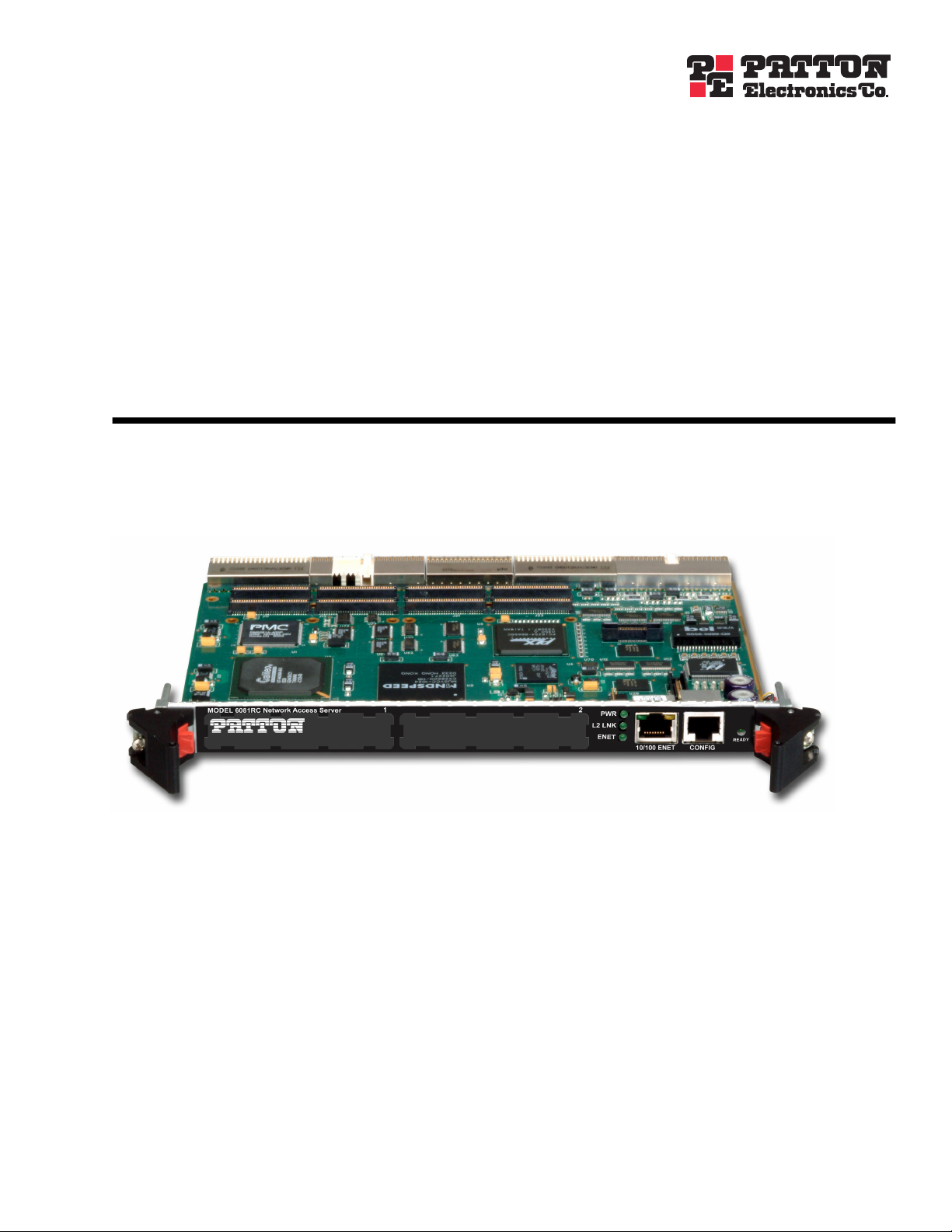
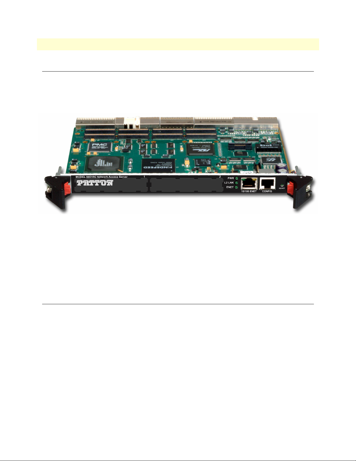
The Model 6081RC Network Access Router (see figure 1) is a MIPS-based processor blade for the ForeFront
Access Infrastructure System (AIS). With hardware and software features optimized for Layer-2/Layer-3 networking, the 6081RC enables the AIS to deliver IP as an access infrastructure element as well as support the
delivery of advanced broadband IP services and applications.
Figure 1. Model 6081RC EdgeRoute Network Access Router
When installed into the 2U, 4U, or 6U ForeFront chassis, the Model 6081RC adds IP routing and access services to installed interfaces, such as xDSL, T1/E1, and STM ports. With the addition of data termination
packages, as well as select edge services packages (e.g. DNS), the Model 6081RC provides full-featured
ipDSLAM functionality to any ForeFront system.
The Model 6081RC preserves legacy TDM services while providing Layer-2/Layer-3 services. TDM data
communications can operate seamlessly within the same hardware, the same chassis, even over the same
wired infrastructure.
Product overview
The Model 6081RC is a frame and service edge-routing resource that provides access-to-edge, packet-based
services for IP termination; forwarding; and frame services within a ForeFront AIS chassis. Ideal for use by service providers, the Model 6081RC provides:
• Aggregation for customer DSL/T1/E1 to framed network services, including Ethernet bridging and VLAN
v1 and v2
• IP routing and forwarding (including complete RIPV2 and OSPF)
• IP access services (including QoS class-based queuing, NAT, and firewall)
The Model 6081RC interfaces to ForeFront line cards via the TDM chassis. The 6081RC processes packets at
45k packets per second (pps). The main differences based on the processor chosen. With access to all 4,096
DS0s the 6081RC allows up to 2,048 discreet full-duplex data connections from a single card.
Introduction

15
Model 6081RC Network Access Server Getting Started Guide
1 • Model 6081RC overview
Network connections may come from any number of ForeFront interfaces. The 6018RC allows any resource
card within ForeFront to deliver TDM and IP/packet services on a DS0-by-DS0, connection-by-connection
basis.
The ForeFront system with the 6081RC allows:
• Any DSL or T1/E1 port to deliver IP access
• This access can be offered simultaneously with other TDM services
• This access can be on the same DSL or T1/E1 link as the same time
Leveraging ForeFront’s any-to-any architecture packet services expands the scope of services from a single
installed system. Providers can now use ForeFront for simultaneous TDM/leased-line and packet service delivery. The smart carrier today wishes to incorporate IP/L2/L3 services as an infrastructure element into their service offering. Based on the foundation of intelligent TDM switching and integrated DACsing, the Patton
ForeFront architecture is highlighted by the following key features:
• Any DS0 level timeslot can be used for either TDM or IP Accesses. This is operator selectable and not lim-
ited by a module, external equipment, or backplane capabilities.
• Access to any DS0 is completely non-blocking. In other words, you are not limited to a specific data
path/backplane, service selection based on the capabilities of a module, or it’s location within a shelf.
• Delivery using Integrated wires through the use of the standard and integrated DACS. Now, both TDM
and IP can be offered on the same DSL, E1, or STM/VC12 ports at the same time. For example, using the
Patton 3086 IAD, you can deliver nx64kbps for TDM access and select the remaining bandwidth for
Packet access. Both services can run at the same time over the same port and terminate at the customer
premise in a single low-cost unit.
• Local network based and processing and termination. We continue legacy TDM services without disrup-
tion, but add value-added protocol internetworking to those TDM applications.
The 6081RC connects directly to all channels (4,096) on the H.110 bus and is agnostic to the line interface
method. The current set of compatible ForeFront resources which interface to the 6081RC include:
• 3096RC G.SHDSL 16 port, 64-kbps–4.6 Mbps, 2-wire access
• 3196RC iDSL 16 port, 64/128/144-kbps, 2-wire access
• 2616RC T1/E1 DACs bulk DS0 cross-connecting
• 6511RC STM-1 (63 E1s, 84 T1s per connection)
Since the 6081RC can go into any of the available slots processing and routing/switching power can be
increased by simply adding more cards to a system. The following tables indicates the number of 6081RCs that
can placed into a single chassis:
Chassis Card support Aggregate packet processing
Model 6276 (2U) Supports up to 4 6081RC 400K pps
Model 6476 (4U) Supports up to 8 6081RC 800K pps
Model 6676 (6U) Supports up to 17 6081RC 1.7M pps
Product overview

16
Model 6081RC Network Access Server Getting Started Guide
1 • Model 6081RC overview
The 6081RC’s applications give life to the hardware features of the 6081RC. Details of the software applications are indicated in the section 6081RC IP Access Server Functionality.
• PPP Bridging and Routing
• VLAN Ethernet Support
• OSPF/RIPv1 and v2 and static routing
• SNMPv1,2,3
• RADIUS AAA Client
• HTTP/web for management
• Apache HTTP/WEB
• NTP Network Time
• Syslog
Additionally, new applications such as L2TP, IPSEC, and MPLS will be added in releases subsequent releases.
The HTTP WEB GUI provides for easy configuration, provisioning, and management. Full SNMP control of
the device allows standardized OSS configuration and provisioning when used with an external FCAPS NMS.
Using SNMP management, the 6081RC is fully configured, managed and monitored via Patton’s ForeSight
EMS solutions. With ForeSight, a Graphical User Interface provides an intuitive, real-life representation of all
installed ForeFront equipment and enables network managers to control and monitor device functions, port
settings and receive device status information and statistics via SNMP. Features include management, a
routable configuration utility, SNMP trap manager, device autoscan, automatic configuration and device firmware downloads and more. The user and NMS have full remote control for provisioning, alarms, accounting,
and security.
Hardware overview
• 6U single-slot card
• MIPS64 CPU (400-MHz RM5261A)
• 128 Mbytes of RAM
• 32 Mbytes or 64 Mbytes of Flash memory
• Capacitor-backed real-time clock with two week’s duration of standby power
• 16 kbytes of non-volatile data storage in EEPROM
Hardware overview
Model 6081RC Network Access Server Getting Started Guide 1 • Model 6081RC overview
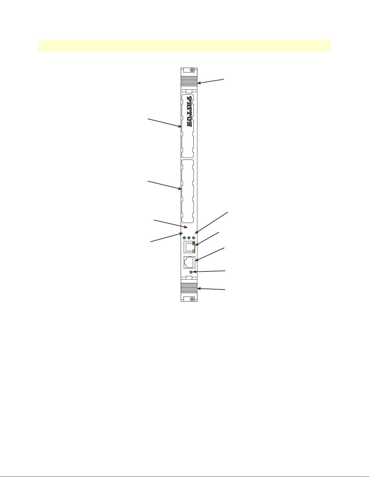
Handle
MODEL 6081RC Network Access Server
Mezzanine Card
Interface 1
1 2
Mezzanine Card
Interface 2
PWR
L2 LINK
LED
ENET
LED
L2 LINK
ENET
10/100 ENET
CONFIG
READY
PWR
LED
10/100 ENET
port
CONFIG
port
READY
LED
Handle
Figure 2. Model 6081RC front panel
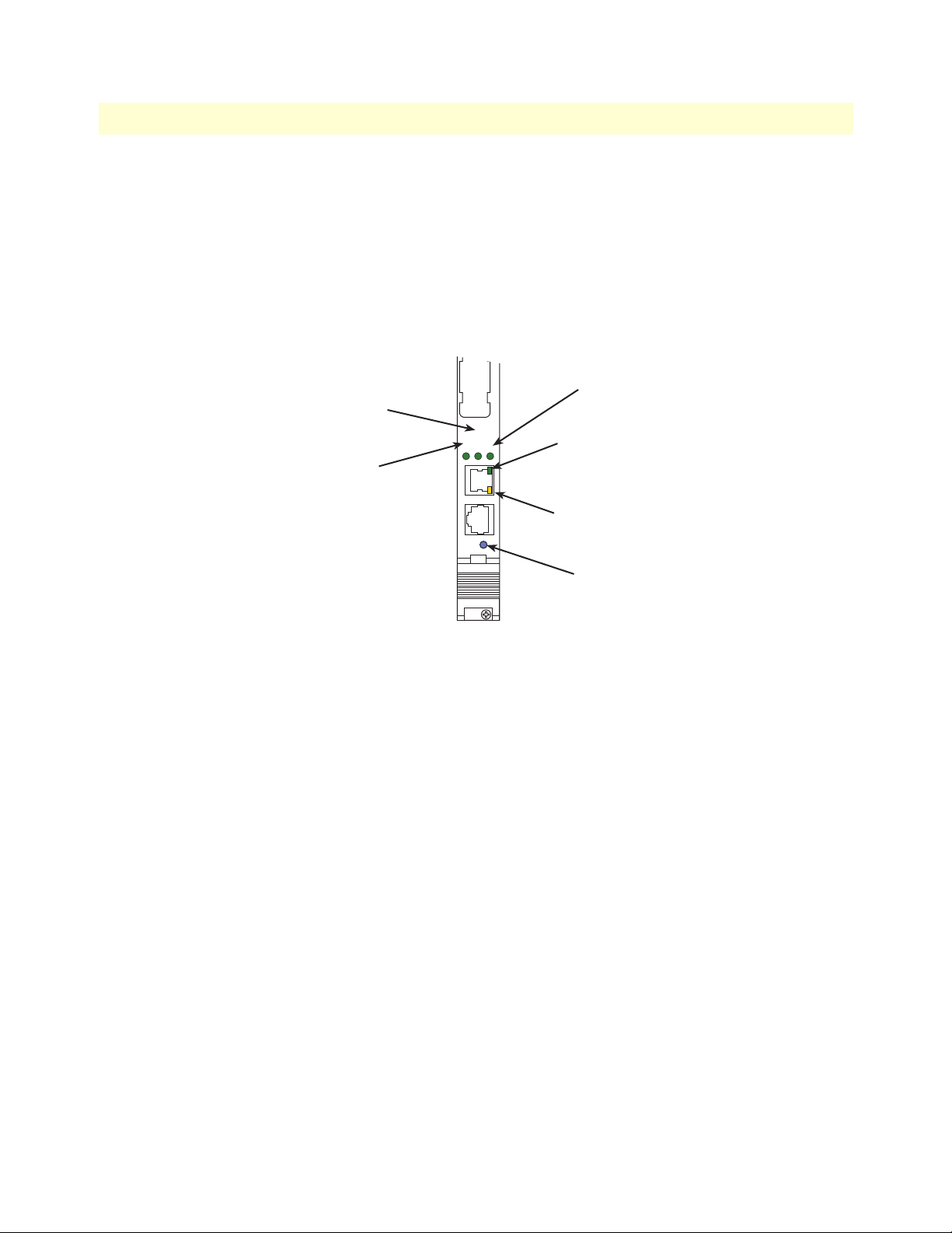
• One front panel 10/100Mbps Ethernet port (see figure 2) with two LEDs
• One front-panel RS232 console port (see figure 2)
• Three front-panel LEDs (see figure 2)
• Two packet switch buss 10/100 Mbps Ethernet ports
• Optional full termination of TDM chassis bus into 1024-channel HDLC controller
• Hot-swap support
Hardware overview 17
Model 6081RC Network Access Server Getting Started Guide 1 • Model 6081RC overview
LAN Ethernet port
Front panel 10/100-Mbps Ethernet LAN port labeled ENET (ETH0) is presented on a RJ-45 connector with
an auto-sensing/full-duplex 10Base-T or 100Base-T interface. Also included are:
• 100Base-TX half-/full-duplex operation (100 + 100)
• 10Base-T half-/full-duplex operation (10 + 10)
• Auto negotiation and fallback
• 10/100 Mbps link and status indicators on the RJ-45 connector
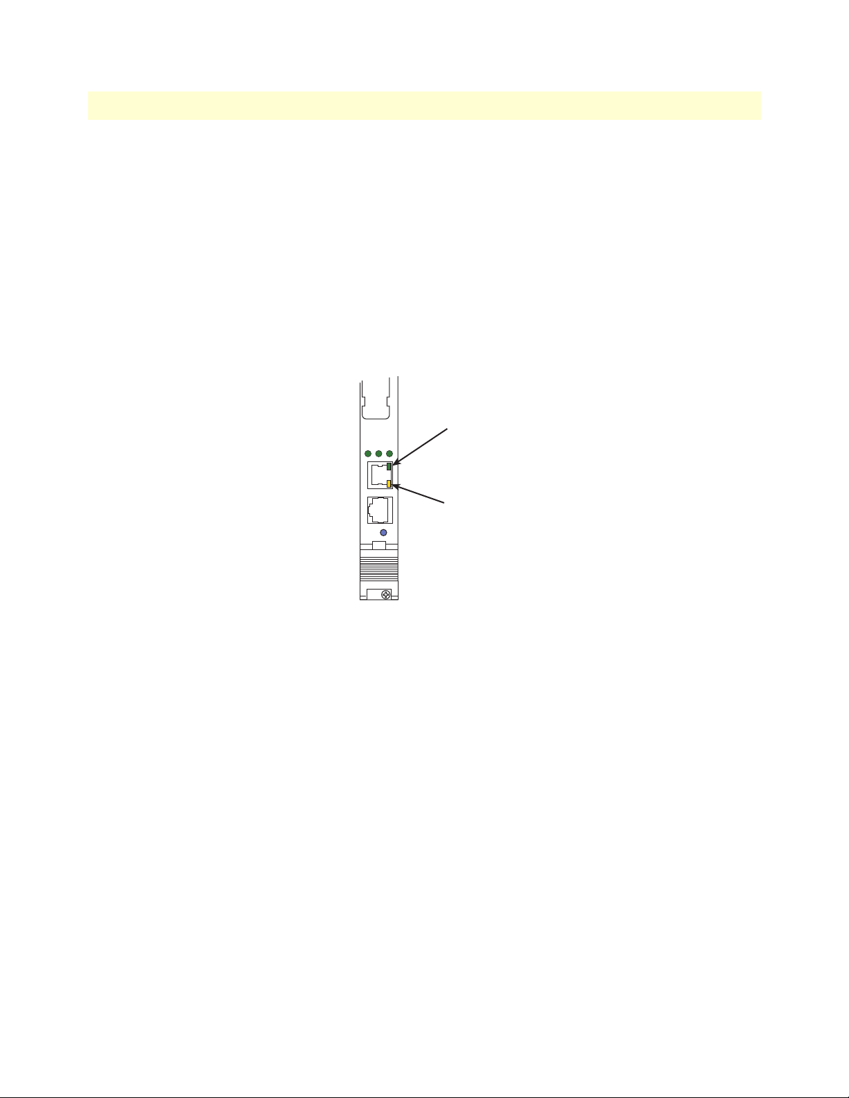
• Two LEDs per port (see figure 3): link/traffic LED (solid green when link is established; flashing green
when the port has traffic) and 10/100 Mbps LED (solid yellow at 100 Mbps; off at 10 Mbps)
2
L2 LINK
ENET
10/100 ENET
PWR
Link/Traffic
LED
CONFIG
READY
10/100 Mbps
LED
Figure 3. Model 6081RC Ethernet port LEDs
Packet switched Ethernet bus (PSB)
• Two internal Ethernet buses connecting over the mid-plane for intercard communication within the chassis
(or chassis segments of the Model 6676)
• Hash-table-based address filtering for up to 8k MAC addresses, unicast and multicast
• Wire-speed DMA transfer of entire MAC frame to system memory
Backplane Ethernet interfaces
• Two internal Ethernet ports connecting to backplane for intercard communication
• Auto-sensing full/half-duplex 10Base-T/100Base-TX operation, IEEE 802.3 compliant
• Hash-table-based address filtering for up to 8k MAC addresses, unicast and multicast
• Wire-speed DMA transfer of entire MAC frame to system memory
Hardware overview 18

Model 6081RC Network Access Server Getting Started Guide 1 • Model 6081RC overview
• Two LEDs per port (see figure 3): link/traffic LED (solid green when link is established; flashing green
when the port has traffic) and 10/100 Mbps LED (solid yellow at 100 Mbps; off at 10 Mbps)
Note When the Fast-Ethernet PMC module (part number
PEC1/FENET/2/TX) is installed in PMC slot 2, you may redirect
one or both internal Ethernet ports B and C to the front-panel RJ-45
connectors B and C (See section “Ethernet interface configuration”
on page 40). Redirecting an Ethernet port to the front panel disables
the backplane interface for that port.
RS-232 control port
The RS-232 port provides for initial configuration of the Model 6081RC’s IP and gateway addresses. The RS232 port supports:
• Asynchronous data rates of 19.2 kbps, 8 data bits, no parity, 1 stop bit.
• An RJ-45 connector with EIA-561 pinouts
• A management interface that supports VT-100 terminals
• Hardware flow control (RTS and CTS)
Power system
The Model 6081RC is powered internally by the ForeFront chassis power system.
Central processing unit
Model 6081RC CPU processing power and memory are listed in the following table:
Model Processor Memory
6081RC/400 RM5261A processor, 400MHz. 128Mb RAM, 32 Mb Flash 45 kpps
a. Packets per second routing without filtering and QoS
Throughput
Temperature
32 to 104°F (0 to 40°C)
Altitude
Maximum operating altitude: 15,000 feet (4,752 meters)
Humidity
5 to 90% relative humidity (RH), non-condensing
Physical dimensions
• 1.75 inches (4.44 cm) height, standard 19-inch (48.26 cm) width, 12-inch (30.48 cm) depth
a
• Weight: 1.5 lbs (0.7 kg)
Hardware overview 19
Model 6081RC Network Access Server Getting Started Guide 1 • Model 6081RC overview
PWR
2
L2 LINK
ENET
CONFIG
10/100 ENET
READY
Management services
• Out-of-band RS-232 configuration port for management and control
• SNMP version 1,2,3 MIB II configuration management
• SYSLOG client
• Remote software upgrade via FTP
• Built-in HTTP server for complete configuration and control using a standard WWW browser
PWR
L2 LINK
LED
ENET
LED
LED
Link/Traffic
LED
10/100 Mbps
LED
READY
LED
Figure 4. Model 6081RC LEDs
Hardware overview 20

Model 6081RC Network Access Server Getting Started Guide 1 • Model 6081RC overview
LED display
Front panel LEDs (see figure 4) display the status of the power system, layer-2 link, the Ethernet LAN port,
power, and the alarms. The LEDs are described in table 3.
Table 3. LED definitions
LED Color Status Meaning
PWR Green On solid Power is being applied.
Flashing The 6081RC is in boot-up sequence.
Off No input power is being applied.
L2 LINK
(Layer 2 Link)
ENET Green On solid Indicates at least one of three Ethernet ports is active
Link/traffic
(front panel
ENET port)
10/100 Mbps
(front panel
ENET port)
READY Blue On Card ready for removal from ForeFront chassis.
Green Flashing The 6081RC is operating properly.
Off Link has not been established.
Off None of the Ethernet ports is active
Green On solid Link is established
Flashing The port has traffic.
Off Link has not been established.
Yellow On solid Port is operating at 100 Mbps
Off Port is operating at 10 Mbps
Off Card not ready for removal from ForeFront chassis.
Hardware overview 21

Chapter 2 Hardware installation
Chapter contents
Introduction..........................................................................................................................................................23
Unpacking the Model 6081RC .............................................................................................................................23
Installing the PMC Ethernet Access Module onto the 6081RC front blade...........................................................24
Model 6081RC blades installation.........................................................................................................................25
Cable installation...................................................................................................................................................27
Connecting the Ethernet ports ........................................................................................................................27
Connecting the 10/100Base-T Ethernet port to an Ethernet switch or hub ...............................................28
Connecting the 10/100Base-T Ethernet port to an Ethernet-capable workstation or PC .................................28
Connecting the EIA-561 RS-232 configuration port (DCE configured) .........................................................29
Completing the hardware installation....................................................................................................................29
22

Model 6081RC Network Access Server Getting Started Guide 2 • Hardware installation
Introduction
This chapter contains the following procedures for installing the Model 6081RC:
• “Unpacking the Model 6081RC”—lists the contents in the 6081RC shipping container
• “Model 6081RC blades installation”—describes installing the Network Access Router in a ForeFront chassis
• “Cable installation” on page 27—describes installing network interface and terminal cables
• “Completing the hardware installation” on page 29—describes testing the 6081RC hardware to verify that
it is ready for software configuration
Unpacking the Model 6081RC
Inspect the shipping carton for external damage. Note any damage before removing the container contents.
Report equipment damage to the shipping carrier immediately for claim purposes. Save all packing materials in
case you need to return an item to the factory for servicing.
The Model 6081RC comes with the following items:
• The Model 6081RC rack card unit
• One RJ45-to-RJ45 cable for use with the console and Ethernet ports
• A DB9-RJ45 (EIA-561) adapter for connecting a PC's serial port to the 6081RC console port
• CD-ROM containing product literature, the Model 6081RC EdgeRoute Network Access Router Getting
Started Guide.
Introduction 23
Model 6081RC Network Access Server Getting Started Guide 2 • Hardware installation
Installing the PMC Ethernet Access Module onto the
6081RC front blade
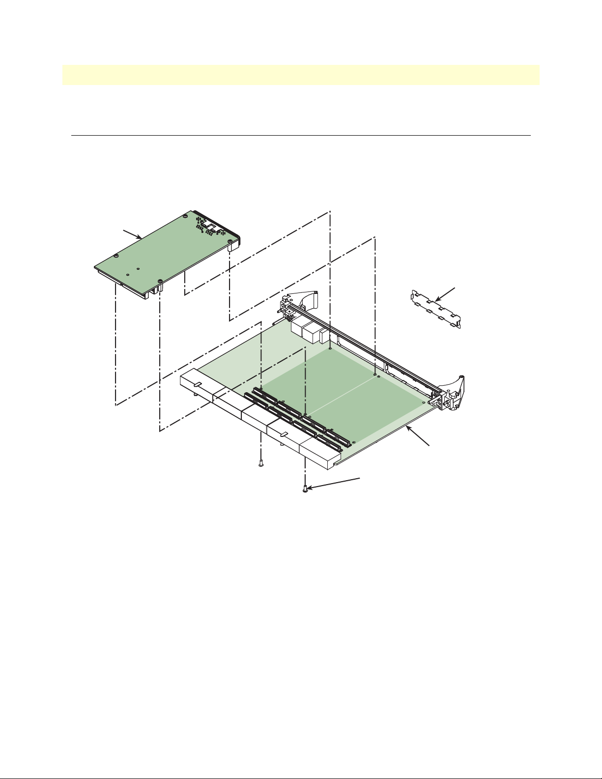
You may purchase an optional PMC Ethernet Access Module for the Model 6081RC. The PMC Ethernet
Access Module may be factory installed, or you may order it separately for installation in the field. The Model
6081RC has two PMC expansion slots, numbered 1 and 2 (see figure 5). The PMC Ethernet Access Module
must only be installed in PMC slot 2, do not install it in PMC slot 1.
PMC card
Remove PMC cover
from front panel
PMC slot 2
PMC slot 1
Do not install the
PMC in this slot
Use M2.5 x 6 mm long screw to
mount PPMC card to 6081RC
Figure 5. Installing the PMC card
6081RC
Installing the PMC Ethernet Access Module onto the 6081RC front blade 24
Model 6081RC Network Access Server Getting Started Guide 2 • Hardware installation
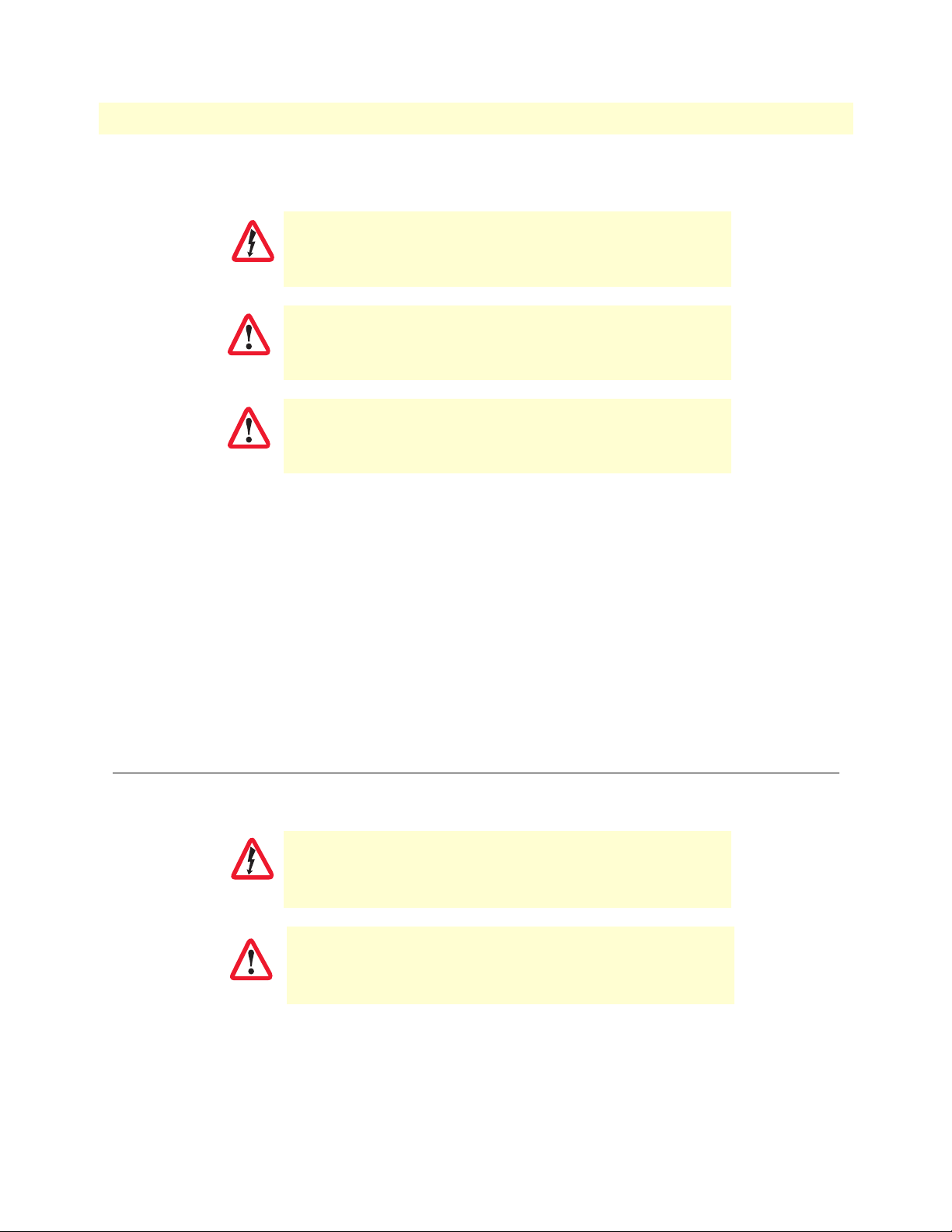
To install the Ethernet Access Module in your Model 6081RC, do the following:
You must wear the anti-static strap to avoid electrostatic damage
to the 6081RC or to the PMC Ethernet Access Module.
CAUTION
The 6081RC must not be installed in the chassis when installing
the PMC Ethernet Access Module.
CAUTION
The PMC Ethernet Access Module must be installed in PMC
slot 2. Do not install it in PMC slot 1.
CAUTION
1. Set the Model 6081RC on a flat anti-static surface with the circuitry facing upward.
2. Remove the PMC slot 2 protective cover from the Model 6081RC front panel (see figure 5 on page 24).
3. Insert the front panel of the PMC card into the cutout for PMC slot 2 on the front panel of the Model
6081RC.
4. Align the two connectors on the PMC card with the corresonding connectors on the Model 6081RC (see
figure 5 on page 24).
5. Gently and firmly press down on the rear of the PMC card, so that the connectors mate and snap
into place.
6. Install the 4 fastening screws as shown in figure 5 on page 24. Gently tighten the screws into place.
Model 6081RC blades installation
The Model 6081RC installs in a Patton ForeFront chassis. The 6081RC is hot-swappable so it is not necessary
to power down the chassis before installing the blade.
Do not work on the system or connect or disconnect cables during periods of
lightning activity.
WARNING
Ultimate disposal of this equipment must be handled according
to all applicable national laws and regulations.
CAUTION
Note Verify that the rack chassis is properly grounded before installing the
Model 6081RC blades. An adequate ground can be achieved by connecting a #10 AWG ground wire between the rack chassis grounding
stud and one of the following ground sources:
Model 6081RC blades installation 25

Model 6081RC Network Access Server Getting Started Guide 2 • Hardware installation
• The building ground rod (generally located at the site’s main ser-
vice entrance)
• A sprinkler system pipe
• A cold-water pipe
• Building structural steel
1. If you have not done so already, remove the Model 6081RC from its shipping container.
Note Be sure to wear the anti-static strap to prevent electrostatic damage to
the blade.
Note The location should be well ventilated. Do not block the rack chassis’
cooling vents.
2. Insert the rear blade into the desired slot in the rack chassis. Make sure the blade is seated properly in the
slot guides.
Card handle
Alignment/ESD pin
Figure 6. Alignment/ESD pin and card handle
3. Gently press the blade into the chassis until the alignment/ESD pin (see figure 6) engages the chassis.
When the blade is fully seated, the red buttons in the handles click up automatically, thus locking the handle and activating the switch (closed position). The click of the button gives a visual and audible confirmation that the board is fully seated.
Model 6081RC blades installation 26
Model 6081RC Network Access Server Getting Started Guide 2 • Hardware installation
Cable installation
This section describes installing the network interface cables.
The interconnecting cables shall be acceptable for external use
and shall be rated for the proper application with respect to volt-
CAUTION
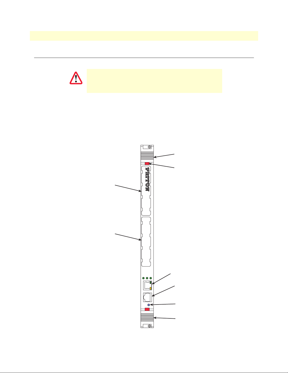
Connecting the Ethernet ports
The Model 6081RC comes with three Ethernet ports. One Ethernet port is presented on the front panel via an
RJ-45 connector (figure 7), and two internal Ethernet ports that connect to the PICMG 2.16 backplane for intercard communication. All Ethernet ports will autosense the correct speed (10 or 100 Mbps) of the connection and
automatically negotiate half or full-duplex operation. This section describes connecting the front panel Ethernet
port on the Model 6081RC to an Ethernet LAN via an Ethernet hub, switch, or workstation.
age, current, anticipated temperature, flammability, and
mechanical serviceability.
Handle
Mezzanine Card
Interface 1
Mezzanine Card
Interface 2
L2 LINK
ENET
10/100 ENET
CONFIG
READY
MODEL 6081RC Network Access Server
1 2
PWR
ButtonButton
10/100 ENET
port
CONFIG
port
READY
LED
Handle
Figure 7. Model 6081RC network and configuration ports
Cable installation 27
 Loading...