

Page 1

NanoServ™
Thin System/Ultra-Thin System
Setup Guide
1.0 What’s included with the NanoServ™
The following items are included with the NanoServ™:
1.
NanoServ™
2.
AC Power Adaptor
3.
CD-ROM with User’s Manual
4.
This Setup Guide
Note
Refer to the User Manual on the CD-ROM for complete information on installation.
2.0 Steps for setting up the NanoServ™
Note
This is a fanless system, so it must be properly mounted to allow for proper cooling. Be sure to use the
metal stand to hold the system upright with the blue LED on top, or mount the system at least 1 or 2
inches away from the flat side surfaces of the system. This will help keep the NanoServ™ cool and
within operating limits.
1.
Verify that the power supply switch is off (located on the back of the NanoServ™).
2.
Plug the monitor into the VGA port.
3.
Plug the keyboard into the PS/2 keyboard port.
4.
Plug the mouse into the PS/2 mouse port.
5.
Plug the printer into the DB-25 printer port (only available on the Thin NanoServ™ system).
6.
Connect the power adaptor to the mains power.
7.
Turn on the power supply switch located on the back of the NanoServ™.
Document Number: 09407U7-001, Rev. A
Part Number: 07M6070-QS
Revised:
August 2, 2006
Technical Support: +1 (301) 975-1007
Sales Office: +1 (301) 975-1000
E-mail: support@patton.com
WWW: www.patton.com
Page 2
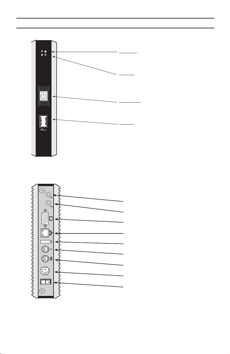
3.0 NanoServ™ Ultra-Thin System
Front panel
Power LED
The power LED lights up when the system is
turned on.
HDD LED
The HDD LED flashes when the system is working.
Please do not turn off the system when HDD
starts running.
Power Switch
Depress the switch to turn on and turn off the
system.
USB Port
The USB port is for a connection to external
devices with a USB interface (keyboard, mouse,
HDD, CD-ROM, Memory Stick, ect.)
Figure 1.
Ultra-Thin System - Front panel
Back panel
Audio Line-Out
Mic-In
VGA Port
RJ-45 10/100 Ethernet Jack
USB Port
PS/2 Mouse (6-pin)
DC-IN 5V
POWER SW
Figure 2.
2
Ultra-Thin System - Back panel
PS/2 Keyboard & Mouse (6-pin)
DC Power Jack (3-pin)
Power supply switch
NanoServ Setup Guide
Page 3

4.0 NanoServ™ Thin System
Front panel
Power LED
The power LED lights up when the system is
turned on.
HDD LED
The HDD LED flashes when the system is working.
Please do not turn off the system when HDD
starts running.
Power Switch
Depress the switch to turn on and turn off the
system.
USB Port
The USB port is for a connection to external
devices with a USB interface (keyboard, mouse,
HDD, CD-ROM, Memory Stick, ect.)
DC-IN 5V
POWER SW
Figure 3.
Thin System - Front panel
Back panel
Audio Line-Out
COM1
Figure 4.
Thin System - Back panel
Mic-In
Serial Port **
VGA Port
RJ-45 10/100 Ethernet Jack
USB Port
PS/2 Mouse (6-pin)
Parallel Port **
PS/2 Keyboard & Mouse (6-pin)
DC Power Jack (3-pin)
Power supply switch
** This feature is only
available for Model 6075.
NanoServ Setup Guide
3
Page 4

5.0 Additional Information
Refer to the
available online at <
•
•
Refer to the
NanoServ™ User Manual
located on the CD-ROM shipped with your NanoServ™ system and
www.patton.com/manuals>
Installing, configuring, operating, and troubleshooting.
Warranty, trademark & compliance
Note
Specifications are subject to change without notice.
Fedora Core Linux
website at
<http://fedora.redhat.com>
Core 5 including installation guides and tutorials.
A.0 Compliance & Safety Information
A.1 Compliance
EMC Compliance:
•
FCC Part 15, Class A
•
EN55022, Class A
EN55024
•
Safety Compliance:
•
IEC/EN 60950-1
for detailed information about:
for information about Fedora
A.2 Radio and TV interference (FCC Part 15)
This equipment generates and uses radio frequency energy, and if not installed and used properly—that is, in
strict accordance with the manufacturer's instructions—may cause interference to radio and television reception. This equipment has been tested and found to comply with the limits for a Class A computing device in accordance with the specifications in Subpart B of Part 15 of FCC rules, which are designed to provide reasonable
protection from such interference in a commercial installation. However, there is no guarantee that interference
will not occur in a particular installation. If the equipment causes interference to radio or television reception,
which can be determined by disconnecting the cables, try to correct the interference by one or more of the following measures: moving the computing equipment away from the receiver, re-orienting the receiving antenna,
and/or plugging the receiving equipment into a different AC outlet (such that the computing equipment and
receiver are on different branches).
4
NanoServ Setup Guide
Page 5
A.3 CE Declaration of Conformity
We certify that the apparatus identified in this document conforms to the requirements of Council Directive
1999/5/EC on the approximation of the laws of the member states relating to Radio and Telecommunication
Terminal Equipment and the mutual recognition of their conformity.
The safety advice in the documentation accompanying the products shall be obeyed.
The conformity to the above directive is indicated by the CE sign on the device.
A.4 Safety Information
•
This device contains no user serviceable parts. The equipment shall be
returned to Patton Electronics for repairs, or repaired by qualified service personnel.
WARNING
•
The external power adapter shall be a listed Limited Power Source.
Ensure that the power cable used meets all applicable standards for the
country in which it is to be installed, and that it is connected to a wall
outlet which has earth ground. The mains outlet that is utilized to
power the devise shall be within 10 feet (3 meters) of the device, shall
be easily accessible, and protected by a circuit breaker.
•
Hazardous network voltages are present in WAN ports regardless of
whether power to the unit is ON or OFF. To avoid electric shock, use
caution when near WAN ports. When detaching the cables, detach the
end away from the device first.
•
Do not work on the system or connect or disconnect cables during periods of lightning activity.
CAUTION
NanoServ Setup Guide
In accordance with the requirements of council directive 2002/96/EC on Waste of
Electrical and Electronic Equipment (WEEE), ensure that at end-of-life you separate
this product from other waste and scrap and deliver to the WEEE collection system in
your country for recycling.
The Interconnecting cables shall be acceptable for external use and shall be rated for
the proper application with respect to voltage, current, anticipated temperature, flammability, and mechanical serviceability
5
Page 6

WARNING
•
To prevent shock or fire hazard, do not expose your
NanoServ™ to rain or moisture.
Never install your NanoServ™ in wet locations.
•
•
To avoid electrical shock, do not open the case. Contact the factory offices for qualified personnel servicing.
Never touch un-insulated terminals or wire unless your power
•
adaptor and display monitor are disconnected.
•
When using the system, avoid using or installing the modem to
the serial port during a storm or lightning.
•
Do not use the modem or a telephone to report a gas leak in the
vicinity of the leak.
•
USB cables are not supplied.
Copyright © 2006, Patton Electronics Company. All rights reserved.
The information in this document is subject to change without notice. Patton Electronics assumes no
liability for errors that may appear in this document.
6
NanoServ Setup Guide
 Loading...