

Page 1
USER
MANUAL
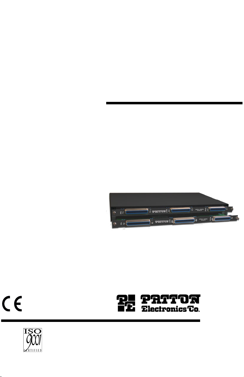
Model 6010 Series
POTS/ISDN Splitter Shelf
This is a Class A device and is intended for use in a
light industrial environment. It is not intended nor
approved for use in an industrial or residential
environment.
Part# 07M6010-UM
Rev. B
Revised 11/10/08
An ISO-9001Certified
Company
SALES OFFICE
(301) 975-1000
TECHNICAL SUPPORT
(301) 975-1007
Page 2

CONTENTS
1.0 Warranty Information ................................................................. 3
1.1 Compliance................................................................................... 3
EMC Compliance:......................................................................... 3
Safety Compliance: ...................................................................... 3
1.2 CE Declaration of Conformity ....................................................... 3
1.3 Service.......................................................................................... 4
1.4 Safety When Working With Electricity .......................................... 4
2.0 General Information.................................................................... 5
3.0 Installing the Shelf...................................................................... 6
4.0 Grounding the Shelf ................................................................... 8
5.0 Cabling Overview........................................................................ 9
6.0 Connector Pinouts...................................................................... 9
6.1 Connector Pinouts Table ............................................................ 10
2
Page 3

1.0 WARRANTY INFORMATION
Patton Electronics
warrants all Model 6010 Series and Model 3101SC
components to be free from defects, and will—at our option—repair or
replace the product should it fail within one year from the first date of the
shipment.
This warranty is limited to defects in workmanship or materials, and does
not cover customer damage, abuse or unauthorized modification. If this
product fails or does not performs as warranted, your sole recourse shall
be repair or replacement as described above. Under no condition shall
Patton Electronics
be liable for any damages incurred by the use of this
product. These damages include, but are not limited to, the following: lost
profits, lost savings and incidental or consequential damages arising
from the use of or inability to use this product.
Patton Electronics
specifically disclaims all other warranties, expressed or implied, and the
installation or use of this product shall be deemed an acceptance of
these terms by the user.
Note
Conformity documents of all Patton products can be viewed
online at www.patton.com under the appropriate product page.
1.1 COMPLIANCE
EMC Compliance:
• EN55022, Class A
• EN55024
Safety Compliance:
• EN 60950-1
1.2 CE DECLARATION OF CONFORMITY
We certify that the apparatus identified in this document conforms to the
requirements of Council Directive 1999/5/EC on the approximation of the
laws of the member states relating to Radio and Telecommunication Terminal Equipment and the mutual recognition of their conformity.
The safety advice in the documentation accompanying this product shall
be obeyed. The conformity to the above directive is indicated by the CE
sign on the device.
3
Page 4
1.3 SERVICE
All warranty and non-warranty repairs must be returned freight prepaid
and insured to Patton Electronics. All returns must have a Return Materials Authorization number on the outside of the shipping container. This
number may be obtained from Patton Electronics Technical Services at:
• Tel: +1
• Email:
• URL:
(301) 975-1007
support@patton.com
http://www.patton.com
Note
Packages received without an RMA number will not be
accepted.
1.4 SAFETY WHEN WORKING WITH ELECTRICITY
•
This device contains no user serviceable parts. The
equipment shall be returned to Patton Electronics for
repairs, or repaired by qualified service personnel.
•
Do not work on the system or connect or disconnect
WARNING
cables during periods of lightning activity.
•
When detaching the telephone network cables,
detach the end away from the device first.
In accordance with the requirements of council directive 2002/96/EC on Waste of Electrical and Electronic
Equipment (WEEE), ensure that at end-of-life you separate this product from other waste and scrap and deliver
to the WEEE collection system in your country for recycling.
4
Page 5

2.0 GENERAL INFORMATION
The Model 6010 Series POTS/ISDN Splitter Shelf comes in four different
models (Table 1). All models should be installed in a 19 inch or 23 inch
rack.
Table 1:
6010 Series Models
Model
6010/1U
6010/3U
6010/4U
6010/9U
Rack Space
Requires 1.75 inches (1U)
Requires 5.25 inches (3U)
Requires 7.00 inches (4U)
Requires 15.5 inches (9U)
5
Page 6

3.0 INSTALLING THE SHELF
The interconnecting cables shall be acceptable for external use and shall be rated for
the proper application with respect to voltage, current, anticipated temperature, flammability, and mechanical serviceability.
CAUTION
The Model 6010 shelf is supplied with mounting brackets and hardware
to allow installation in a 19 inch or 23 inch rack. By repositioning the
mounting brackets, the shelf can be installed with the connectors facing
the front or rear. With the connectors facing the front, a depth of 10
inches would be sufficient to mount the shelf with cables installed.
Note
See Table 1 on page 5 for rack space requirements for each
6010 model.
Figure 1.
Figure 2.
6010/1U
6010/3U
6
Page 7

Figure 3.
6010/4U
Figure 4.
6010/9U
7
Page 8

4.0 GROUNDING THE SHELF
To comply with the Network Equipment Building Systems (NEBS)
requirements, a suitable ground must be provided. The ground lug on
the chassis
must be used
for the ground wire.
Figure 5.
Grounding the Model 6010
8
Page 9

5.0 CABLING OVERVIEW
The interconnecting cables shall be acceptable for external use and shall be rated for
the proper application with respect to voltage, current, anticipated temperature, flammability, and mechanical serviceability.
CAUTION
The Model 6010 Splitter Shelf cabling configurations will vary depending
on installation locations and the number of lines supported by the
DSLAM. However, the physical interface to the Front Panel connectors
are standard 50-pin RJ-21 type receptacle connectors. Each Splitter
card uses 24 pairs of the 25 pairs available on each 50-pin connector.
6.0 CONNECTOR PINOUTS
• DSL signals to and from the DSLAM enter the 6010 splitter shelf using
the left most telephone connectors, designated ‘
• Signals to and from the LINE (outside plant) enter the 6010 splitter shelf
using the centertelephone connectors, designated ‘
• Cables to and from the central office switch enter the 6010 splitter shelf
via the right hand telephone connectors, designated ‘
Note
See Table 2 on page 10 for connector pinouts.
DSL
’ interface.
LINE
PSTN
’ interface.
’ interface.
9
Page 10

6.1 CONNECTOR PINOUTS TABLE
Filter
No.
ADSL
Tip
1
26 1 26 1 26 1
Connector
Ring
LINE
Tip
Connector
Ring
PSTN
Tip
Connector
2 27 2 27 2 27 2
3 28 3 28 3 28 3
4 29 4 29 4 29 4
5 30 5 30 5 30 5
6 31 6 31 6 31 6
7 32 7 32 7 32 7
8 33 8 33 8 33 8
9 34 9 34 9 34 9
10 35 10 35 10 35 10
11 36 11 36 11 36 11
12 37 12 37 12 37 12
13 38 13 38 13 38 13
14 39 14 39 14 39 14
15 40 15 40 15 40 15
16 41 16 41 16 41 16
17 42 17 42 17 42 17
18 43 18 43 18 43 18
19 44 19 44 19 44 19
20 45 20 45 20 45 20
21 46 21 46 21 46 21
22 47 22 47 22 47 22
23 48 23 48 23 48 23
24 49 24 49 24 49 24
Table 2:
Model 6010 Series Connector Pinouts
Ring
10
Page 11

NOTES
_________________________________________________________
_________________________________________________________
_________________________________________________________
_________________________________________________________
_________________________________________________________
_________________________________________________________
_________________________________________________________
_________________________________________________________
_________________________________________________________
_________________________________________________________
_________________________________________________________
_________________________________________________________
_________________________________________________________
_________________________________________________________
_________________________________________________________
_________________________________________________________
_________________________________________________________
_________________________________________________________
_________________________________________________________
_________________________________________________________
_________________________________________________________
11
Page 12

NOTES
_________________________________________________________
_________________________________________________________
_________________________________________________________
_________________________________________________________
_________________________________________________________
_________________________________________________________
_________________________________________________________
_________________________________________________________
_________________________________________________________
_________________________________________________________
_________________________________________________________
_________________________________________________________
_________________________________________________________
_________________________________________________________
_________________________________________________________
_________________________________________________________
_________________________________________________________
_________________________________________________________
_________________________________________________________
_________________________________________________________
_________________________________________________________
Copyright © 2008
Patton Electronics Company
All Rights Reserved
12
 Loading...