

Page 1
USER
MANUAL
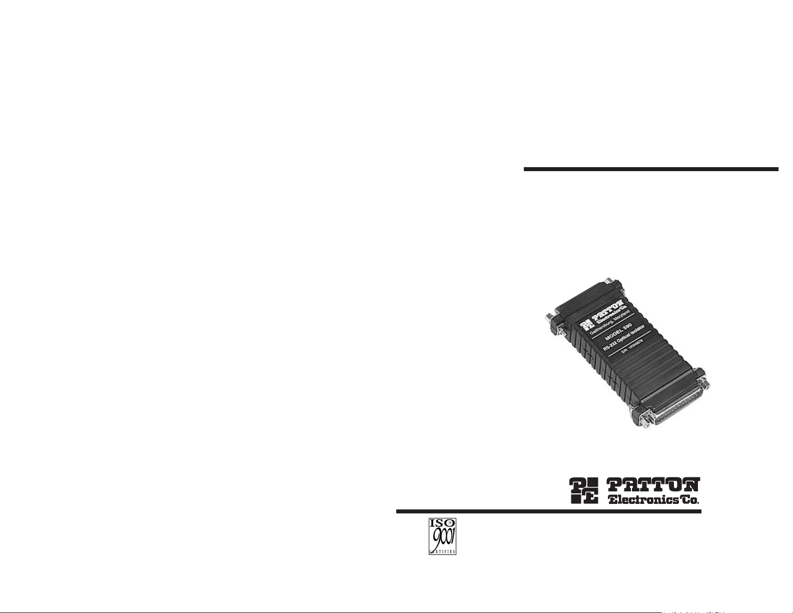
MODEL 592 and
MODEL 594
RS-232 to RS-232
Optical Isolators
SALES OFFICE
(301) 975-1000
TECHNICAL SUPPORT
(301) 975-1007
http://www.patton.com
Part# 07M592-B
Doc# 055031UB
Revised 5/28/98
CERTIFIED
An ISO-9001
Certified Company
Page 2

1.0 WARRANTY INFORMATION
Patton Electronics
warrants all Model 592/594 components to be
free from defects, and will—at our option—repair or replace the product
should it fail within one year from the first date of shipment.
This warranty is limited to defects in workmanship or materials, and
does not cover customer damage, abuse or unauthorized modification.
If this product fails or does not perform as warranted, your sole
recourse shall be repair or replacement as described above. Under no
condition shall Patton Electronics be liable for any damages incurred
by the use of this product. These damages include, but are not limited
to, the following: lost profits, lost savings and incidental or
consequential damages arising from the use of or inability to use this
product. Patton Electronics specifically disclaims all other warranties,
expressed or implied, and the installation or use of this product shall be
deemed an acceptance of these terms by the user.
1.1 RADIO AND TV INTERFERENCE
The Model 592/594 generates and uses radio frequency energy,
and if not installed and used properly—that is, in strict accordance with
the manufacturer's instructions—may cause interference to radio and
television reception. The Model 592/594 has been tested and found to
comply with the limits for a Class A computing device in accordance
with the specifications in Subpart J of Part 15 of FCC rules, which are
designed to provide reasonable protection from such interference in a
commercial installation. However, there is no guarantee that
interference will not occur in a particular installation. If the Model
592/594 does cause interference to radio or television reception, which
can be determined by disconnecting the RS-232 interface, the user is
encouraged to try to correct the interference by one or more of the
following measures: moving the computing equipment away from the
receiver, re-orienting the receiving antenna and/or plugging the
receiving equipment into a different AC outlet (such that the computing
equipment and receiver are on different branches).
1.2 CE NOTICE
The CE symbol on your Patton Electronics equipment indicates
that it is in compliance with the Electromagnetic Compatibility (EMC)
directive and the Low Voltage Directive (LVD) of the Union European
(EU). A Certificate of Compliance is available by contacting Technical
Support.
1
1.3 SERVICE
All warranty and nonwarranty repairs must be returned freight
prepaid and insured to Patton Electronics. All returns must have a
Return Materials Authorization number on the outside of the shipping
container. This number may be obtained from Patton Electronics
Technical Services at:
telephone: (301) 975-1007
email: support@patton.com
web address: http://www.patton.com
NOTE: Packages received without an RMA number will not be
accepted.
Patton Electronics' technical staff is also available to answer any
questions that might arise concerning the installation or use of your
Patton Model 592/594. Technical Service hours: 8AM to 5PM EST,
Monday through Friday.
2
Page 3

4.0 INSTALLATION
The Model 592/594 requires no configuration. It plugs directly into
the DTE and connects to the DCE by a short cable. Power is supplied
to the unit by a wall-mount adapter. Refer to the diagram below and
follow the instructions to install the Model 592/594.
1) Plug the DB-25 female connector labeled “DCE” of Model
592/594 directly into the DB-25 male RS-232 port on your
DTE device (PC, terminal, host, etc.). If your DTE device has
a connector other than a male DB-25, or if you need greater
distance from the RS-232 interface, use
straight through
cable.
2) Connect the DB-25 female connector labeled “DTE” on the
Model 592/594 to your DCE device.
3) Supply power to the Model 592/594 using the wall-mount AC
power supply included with the unit. The AC power supply
provides 5V dc @ 300mA to the board.
DTE Device Interface DCE Device Interface
(DB-25 Female) (DB-25 Female)
TD (2) ------------------------------(2) TD
RD (3)-----------------------------(3) RD
RTS (4)-----------------------------(4) RTS
CTS (5)-----------------------------(5) CTS
DSR (6)-----------------------------(6) DSR
CD (8)-----------------------------(8) CD
DTR (20)-----------------------------(20) DTR
When installed according to the instructions above, the Model
592/594 is designed to operate transparently–just set it and forget it.
There is no ON/OFF switch; the unit is operational as soon as power is
supplied.
2.0 GENERAL INFORMATION
Thank you for your purchase of this Patton Electronics product.
This product has been thoroughly inspected and tested and is
warranted for One Year parts and labor. If any questions or problems
arise during installation or use of this product, please do not hesitate to
contact Patton Electronics Technical Services at (301) 975-1007.
2.1 FEATURES
• Asynchronous Operation
• Full or Half-Duplex
• Model 592 Supports Data Rates up to 19.2 kbps
• Model 594 Supports Data Rates up to 115.2 kbps
• 2000 Vrms/ 2500 V Peak Isolation
• Powered by External AC Wall Mount Transformer
• Miniature Size
• Made in USA
2.2 DESCRIPTION
The Patton Model 592 and 594 RS-232 to RS-232 Optical
Isolators guard your asynchronous data and equipment from the
hazards of ground looping. Plugging directly into your DTE hardware,
the Model 592/594 provides 2500V peak of DTE/DCE isolation. The
Model 592 supports data rates to 19.2 Kbps. Model 594 supports rate
up to a quick 115.2 kbps! Power is supplied by an external wall-mount
AC transformer.
The Model 592/594’s isolation capability not only guards your RS232 TD and RD signals, it also protects the RTS, CD, CTS, DSR, and
DTR control signals as well. The Model 592/594 is easy to install, and
is transparent to flow control between connected devices -- you can run
hardware
or
software control! A DB-25 female on the DCE side plugs
into your DTE device and a DB-25 female on the DTE side connects by
cable to your DCE device. The Model 592/594 is made in the USA.
Warning: This product will not provide complete protection should your
equipment or building be subject to a direct lightening hit.
3 4
Model 590
RS-232 Opto-Isolater
Gaithersburg, Maryland
S/N 1 2 3 4 5 6 78
DTE
DCE
Power Supply Jack
Connect to
“DCE”
Connect to
“DTE”
Page 4

APPENDIX A
PATTON MODEL 592/594 SPECIFICATIONS
Transmission
Format: Asynchronous, full or half duplex
Interface Standard: EIA RS-232-E
Connectors: DB-25 female on DCE side (direct
connection to DTE equipment); DB-25
female on DTE side (connects by cable to
DCE equipment)
Data Rates: Up to 19.2 kbps (Model 592)
Up to 115.2 kbps (Model 594)
Power Supply: External wall-mount transformer.
Isolation: 2000 Vrms/2500 V Peak Isolation
Dimensions: 3.8”L x 2.1”W x 0.79”H
Temperature Range: 0-60
°
C (32-140°F)
Altitude: 0-10,100 feet
Humidity: 5 to 95% noncondensing
5
APPENDIX B
PATTON 592/594 INTERFACE STANDARDS
Copyright © 1998
Patton Electronics Company
All Rights Reserved
6
1- (FG) Frame Ground
2- (TD) Transmit Data To Model 592/4
3- (RD) Receive Data From Model 592/4
4- (RTS) Request to Send To Model 592/4
5- (CTS) Clear to Send From Model 592/4
6- (DSR) Data Set Ready From Model 592/4
7- (SG) Signal Ground
8- (DCD) Data Carrier Detect From Model 592/4
To Model 592/4 Data Term. Ready (DTR) - 20
DIRECTION DB-25 FEMALE CONNECTOR LABELED “DCE” DIRECTION
1- (FG) Frame Ground
2- (TD) Transmit Data From Model 592/4
3- (RD) Receive Data To Model 592/4
4- (RTS) Request to Send From Model 592/4
5- (CTS) Clear to Send To Model 592/4
6- (DSR) Data Set Ready To Model 592/4
7- (SG) Signal Ground
8- (DCD) Data Carrier Detect To Model 592/4
From Model 592/4 Data Term. Ready (DTR) - 20
DIRECTION DB-25 FEMALE CONNECTOR LABELED “DTE” DIRECTION
 Loading...