

Page 1
USER
MANUAL
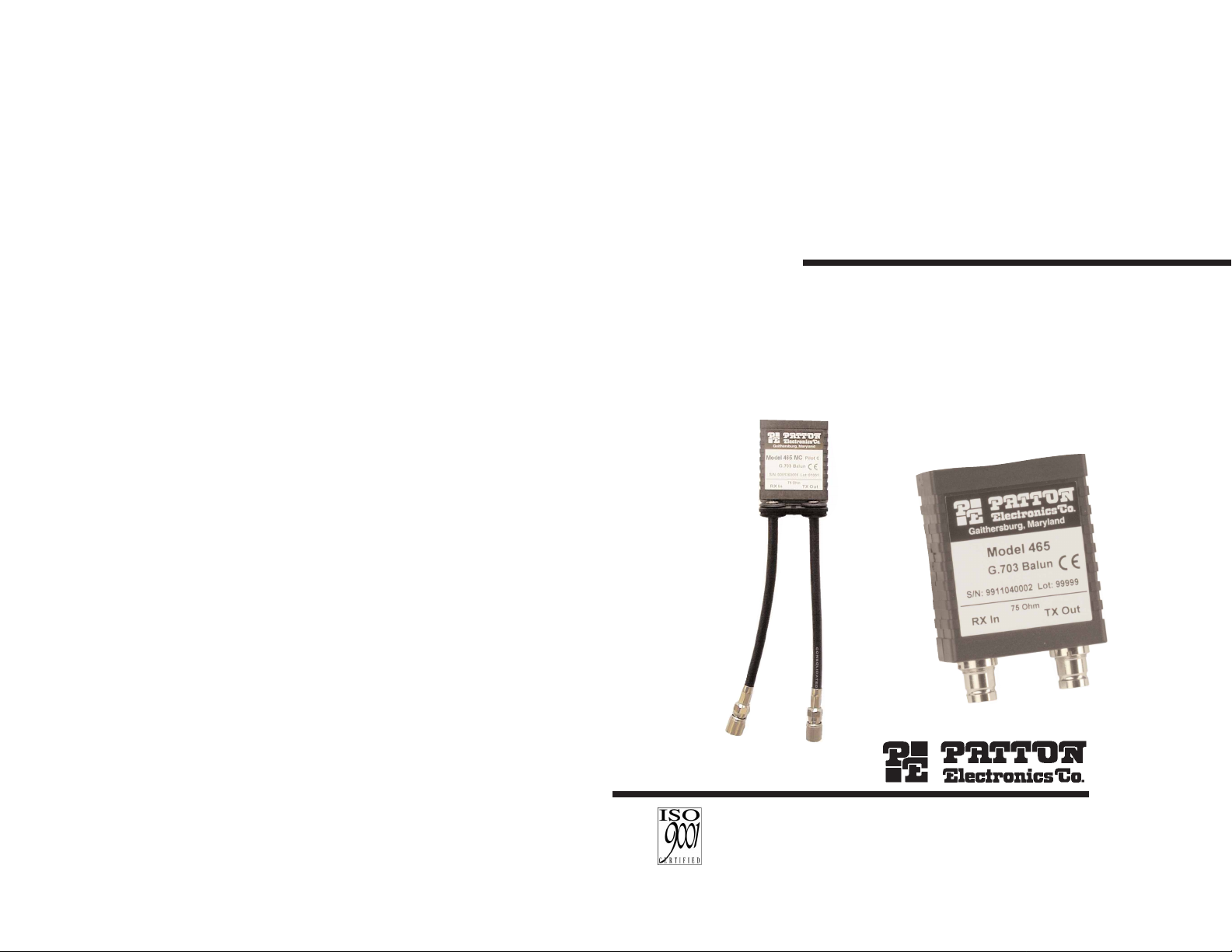
MODEL 465F and 465MC
G.703 Coax to Twisted Pair
Adapters (BALUNs)
SALES OFFICE
(301) 975-1000
TECHNICAL SUPPORT
(301) 975-1007
http://www.patton.com
Part # 07M465-A
Doc. #019141UA
Revised 05/01/00
An ISO-9001
Certified Company
Page 2

1.0 WARRANTY INFORMATION
Patton Electronics warrants all Model 465 Series components to
be free from defects, and will—at our option—repair or replace the
product should it fail within one year from the first date of shipment. This
warranty is limited to defects in workmanship or materials, and does not
cover customer damage, abuse or unauthorized modification. If this
product fails or does not perform as warranted, your sole recourse shall
be repair or replacement as described above. Under no condition shall
Patton Electronics be liable for any damages incurred by the use of this
product. These damages include, but are not limited to, the following:
lost profits, lost savings and incidental or consequential damages arising
from the use of or inability to use this product. Patton Electronics
specifically disclaims all other warranties, expressed or implied, and the
installation or use of this product shall be deemed an acceptance of
these terms by the user.
1.1 CE NOTICE
The CE symbol on your Patton Electronics equipment indicates that
it is in compliance with the Electromagnetic Compatibility (EMC)
directive and the Low Voltage Directive (LVD) of the Union European
(EU). A Certificate of Compliance is available by contacting Patton
Technical Support.
1.2 SERVICE AND SUPPORT
All warranty and non-warranty repairs must be returned freight
prepaid and insured to Patton Electronics. All returns must have a
Return Materials Authorization number on the outside of the shipping
container. This number may be obtained from Patton Electronics
Technical Service at (301) 975-1007; http://www.patton.com: or,
support@patton.com.
NOTE: Packages received without an RMA number will not be
accepted.
Patton Electronics' technical staff is also available to answer any
questions that might arise concerning the installation or use of your
Model 465 Series. Technical Service hours: 8AM to 5PM EST, Monday
through Friday.
1
2
2.0 GENERAL INFORMATION
Thank you for your purchase of this Patton Electronics product.
This product has been thoroughly inspected and tested and is
warranted for One Year parts and labor. If any questions or problems
arise during installation or use of this product, please do not hesitate to
contact Patton Electronics Technical Support at (301) 975-1007.
2.1 FEATURES
• Connects 75 Ohm 1.6/5.6 mm. dual coax terminations to 120 Ohm
twisted pair, RJ-45 termination
• Bi-directional signal conversion according to CCITT G.703
• Data Rates up to 2.048 Mbps (E1)
• Low profile design
• No AC power or batteries required
• Two versions: miniature balun and balun with two six in./15.25
mm. cables
2.2 DESCRIPTION
The Patton 465 Series enables 75 Ohm coax hardware to
communicate with 120 Ohm twisted pair equipment. The Model 465
Series specifically addresses the ONP (Open Network Provision)
requirement that European PTTs offer 120 Ohm twisted pair
terminations to their customers. Some PTTs and private carriers are
standardized on 75 Ohm coax, or have customers whose CPE has only
75 Ohm coax connections. The 465 Series presents a ready solution to
this termination mismatch. Supporting E1 data rates to 2.048 Mbps, the
465 Series converts 75 Ohm signals to 120 Ohm, and vice versa.
The Model 465 Series is available in two versions; a miniature
balun and a balun with two six in./15.25 mm. cables.
Page 3

Twisted Pair/Coaxial Cable Connections
See Figure 1 below for RJ-45 pin connections.
1) Both the 465MC and the 465F have a shielded RJ-45 jack.
2) The 465MC has male 1.6/5.6 mm. coaxial connectors (i.e., center
conductor is a pin) and the 465F has female 1.6/5.6 mm. coaxial
connectors (i.e., center conductor is a receptacle).
3) Pins 1 and 2 of the RJ-45 jack are the transmit data signals.
4) Pins 4 and 5 of the RJ-45 jack are receive data signals.
5) The shield of the RX IN coax connector may be connected to RJ-45
(pin 6) by jumper JP2 (on).
6) The shield of the TX OUT coax connector is connected via JP1 to
transmit data shield, RJ-45 (pin 3) and the shield of the RJ-45 jack.
Transmit data shield on the RJ-45 (pin 3) jack is always connected to
the shield of the RJ-45 jack.
4
RJ-45 Jack Pin No./Signal
1 - Transmit Data
2 - Transmit Data
3 - Transmit Data Shield
4 - Receive Data
5 - Receive Data
6 - Receive Data Shield
7 - no connection
8 - no connection
Figure 1. RJ-45 Pin Connections
3.0 CONFIGURATION
The following section describes configuring the Model 465 Series.
The Model 465 Series is preset to work in most applications without
additional configuration. The only user-configurable parameters are the
shield connections between the 75 Ohm coax and 120 Ohm interfaces.
The shields are connected between the modular jack and dual
1.6/5.6 connectors (see Appendix B). The shield on the RJ-45 jack
always connects to the transmit data shield (pin 3). RJ-45 (pin 3)
connects to the coax transmit shield via JP1. RJ-45 (pin 6) connects to
the coax receive shield via JP2. Remove the jumpers to break the
connection.
The factory setting leaves both jumpers JP1 and JP2 (see Table 1
above) in place, passing both shield connections through. To break one
or both of the shield connections, follow the instructions below.
1) Insert a flat blade screwdriver into the slot on the side of
the 465 Series case and twist. The case will pop
open, exposing the PC board.
2) Holding the PC board with the RJ-45 jack facing left,
locate jumper JP1 toward the top of the board and JP2
toward the bottom of the board. Remove the desired
jumper(s) to break one or both shield connections.
NOTE: Do not lose the jumper(s).
3) Re-align the case halves and end inserts and snap the case
halves back together.
3
Table 1. Jumper settings
RJ-45 (120 ohm) Jumper Coax 1.6/5.6 mm. (75 ohm)
Pin 3 (TX Shield) JP1 TX Out Coax Shield
Pin 6 (RX Shield) JP2 RX In Coax Shield
Page 4

4.0 INSTALLATION
The Model 465 Series requires no AC power or batteries for operation.
After making any neccessary configuration changes (see section 3.0), simply
plug in the modular and coax cables as indicated on the case. The pin
configuration of the 120 Ohm RJ-45 modular connector appears below:
RJ-45 Pin(s) Function
1 & 2.......................................................TX Pair
3.......................................................TX Shield
4 & 5.......................................................RX Pair
6.......................................................RX Shield
5 6
APPENDIX A
PATTON ELECTRONICS 465 SERIES
SPECIFICATIONS
Transmission Line: ITU/CCITT G.703 (unstructured)
Data Rate: 2.048 Mbps maximum
Unbalanced Coaxial
Connection: Dual coax 1.6/5.6 mm. connectors, male or
female (RG 59 or 2002 coax)
Nominal Line Impedance = 75 Ohms
Balanced Twisted Pair
Connection: Single 8-pin, shielded RJ-45 jack
Two twisted-pair
Nominal Line Impedance = 120 Ohms
Power Supply: None required, passive device
Coaxial Twisted Pair
Isolation: 500V rms
Compliance: CE approved
Dimensions: 0.8H x 1.7W x 2.7D in.
2.03H x 4.32W x 6.86D cm.
Page 5

APPENDIX B
PATTON ELECTRONICS 465 SERIES
BLOCK DIAGRAM
© Copyright 2000
Patton Electronics Company
All Rights Reserved
7
JP1
JP2
Coax Shield
Signal
Conversion
RJ-45
(pin 3)
Shield
Twisted Pair
(RJ-45)
Coax Shield
Tansmit
Data
Receive
Data
TX Out
RX In
Coax
RJ-45 (pin 6) Shield
RJ-45
Jack
Shield
Page 6

 Loading...