

Page 1
USER
MANUAL
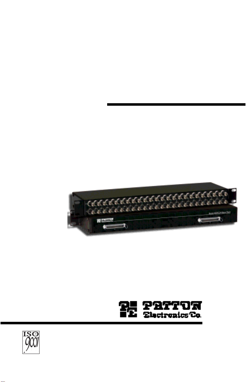
MODEL 450RC24
Ultra High Density
G.703 Balun P anel
(75-Ohm Coax to
120-Ohm 50-pin Telco)
CERTIFIED
An ISO-9001
Certified
Company
Part # 07M450RC24-A
Doc. # 019151U
Released 6/25/01
SALES OFFICE
(301) 975-1000
TECHNICAL SUPPORT
(301) 975-1007
Page 2

TABLE OF CONTENTS
1.0 Warranty Information .................................................................. 3
1.1 CE Notice...................................................................................... 3
1.2 Service and Support..................................................................... 3
2.0 General Information..................................................................... 4
2.1 Features........................................................................................ 4
2.2 Description.................................................................................... 5
3.0 Installation.................................................................................... 6
3.1 Reversing the Cover..................................................................... 6
3.2 Connecting the 75-Ohm BNC Ports.............................................. 7
3.3 Connecting the 120 Ohm 50-pin Telco Ports................................ 7
A Model 450RC24 Specifications................................................... 8
A.4 Transmission Line ..........................................................................8
A.5 Data Rate .......................................................................................8
A.6 75-Ohm Connection ......................................................................8
A.7 120-Ohm Connection ....................................................................8
A.8 Power Supply .................................................................................8
A.9 Link-to-Data Isolation .....................................................................8
A.10 Temperature Range .......................................................................8
1.11 Dimensions (Without Handles)..................................................... 8
B Model 450RC24 Factory Replacement Part............................... 9
C Model 450RC24 Block Diagram................................................ 10
2
Page 3

1.0 WARRANTY INFORMATION
Patton Electronics
warrants all Model 450RC24 components to be free
from defects, and will—at our option—repair or replace the product
should it fail within one year from the first date of shipment. This warranty
is limited to defects in workmanship or materials, and does not cover
customer damage, abuse or unauthorized modification. If this product
fails or does not perform as warranted, y our sole recourse shall be repair
or replacement as described above. Under no condition shall
Electronics
be liable for any damages incurred by the use of this prod-
Patton
uct. These damages include, but are not limited to, the following: lost
profits, lost savings and incidental or consequential damages arising
from the use of or inability to use this product.
Patton Electronics
specifically disclaims all other warranties, expressed or implied, and the
installation or use of this product shall be deemed an acceptance of
these terms by the user.
1.1 CE NOTICE
The CE symbol on your Patton Electronics equipment indicates that it is in
compliance with the Electromagnetic Compatibility (EMC) directive and
the Low Voltage Directive (LVD) of the Union European (EU). A Certificate
of Compliance is available by contacting Patton Technical Support.
1.2 SERVICE AND SUPPORT
All warranty and non-warranty repairs must be returned freight prepaid
and insured to Patton Electronics. All returns must have a Return Materials Authorization number on the outside of the shipping container. This
number may be obtained from Patton Electronics Technical Support at
+1 (301) 975-1007; www.patton.com
; or
support@patton.com
.
Note
Packages received without an RMA number will not be
accepted.
Patton Electronics' technical staff is also available to answer any questions that might arise concerning the installation or use of your Model
450RC24. Technical Support hours:
through Friday
.
8 AM to 5 PM EST, Monday
3
Page 4

2.0 GENERAL INFORMATION
Thank you for your purchase of this Patton Electronics product. This
product has been thoroughly inspected and tested and is warranted for
One Year parts and labor. If any questions or problems arise during
installation or use of this product, please do not hesitate to contact Patton Electronics Technical Support at (301) 975-1007.
2.1 FEATURES
• Connects 75-Ohm dual coax to 120-Ohm twisted pair
• Bi-directional signal conversion according to CCITT G.703
• Data rates up to
• 1 U high enclosed chassis
• Reversable cover with integrated mounting ears
• Mounts in standard 19-in. (48.3 cm) rack
• No AC power or batteries required
• 24 female BNC pairs
• Two 50-pin Telco connectors for 120-Ohm interface
2.048 Mbps
4
Page 5

2.2 DESCRIPTION
The Patton 450RC24 G.703 Telco balun panel (see Figure 1) matches
24 sets of dual 75-ohm coax connections to 120-ohm Telco connections.
This function enables carriers to provide 120-ohm G.703 service to customers retaining 75-ohm CPE hardware. It also enables carriers who
have standardized on 75-ohm coax to provide 120-ohm terminations to
their customers (in keeping with European ONP requirements).
RX
1
TX
2
3
4
5
6
7
8
9
10
11
12
13
14
15
16
17
18
19
20
21
22
23
RX
24
TX
Figure 1.
Model 450RC24
Supporting E1 data rates to 2.048 Mbps, the Patton 450RC24 panels bidirectionally match signal impedance and pulse shapes according to the
CCITT G.703 standard. The Patton 450RC24 balun panels mount in a
standard 19-in. (48.3 cm) rack.
5
Page 6

3.0 INSTALLATION
24
19
20
21
22
23
This section describes how to connect to the twisted pair interface and
the serial interface. This section also describes procedures to rev erse the
cover of the unit in order to mount the 50-pin Telco ports on the front of
the unit.
3.1 REVERSING THE COVER
The cover of the balun rack can be reversed in order to mount the 50-pin
Telco ports on the front of the unit, flush with the mounting ears. To
remove the cover of the unit, remove the four cover screws from each
side of the unit (see Figure 2), lift the cover straight up, and re-attach the
cover with the 50-pin Telco ports on the front of the unit.
Cover screw
(8 places)
18
RX
TX
Figure 2.
Removing the cover screws
6
Page 7

3.2 CONNECTING THE 75-OHM BNC PORTS
The 75-Ohm BNC ports on the front of the balun rack are labeled TX
(transmit data input) and RX (receive data output). Connect the G.703
lines as shown in Figure 3.
Receive
Transmit
RX
TX
The number of each coax pair corresponds to the two 50-pin Telco connector s pin numbers
on the rear panel. Coax pairs 1—12 terminate on Telco connector J1; 13—24 terminate on J2.
RX
1
TX
Figure 3.
Model 450RC24 front panel
RX
24234567891011121314151617181920212223
TX
The numbers on each coax pair correspond to the 50-pin Telco ports on
the rear of the unit.
3.3 CONNECTING THE 120 OHM 50-PIN TELCO PORTS
The 120-Ohm balanced pairs are accessed via the 50-pin Telco connectors J1 and J2.
J2 J1
J2 J1
Figure 4.
Model 450RC24 rear panel
7
Page 8

APPENDIX A
MODEL 450RC24 SPECIFICATIONS
A.4 TRANSMISSION LINE
CCITT G.703 (unstructured)
A.5 DATA RATE
2.048 Mbps
A.6 75-OHM CONNECTION
Dual coax female BNC
A.7 120-OHM CONNECTION
50-pin T elco connector
A.8 POWER SUPPLY
None required
A.9 LINK-TO-DATA ISOLATION
500 volts AC/DC
A.10 TEMPERATURE RANGE
32–122°F (0–50°C)
1.11 DIMENSIONS (WITHOUT HANDLES)
19.0 W x 3.5 H x 1.9 D inch (48.3 W x 8.9 H x 4.8 D cm)
8
Page 9

APPENDIX B
MODEL 450RC24 FACTORY REPLACEMENT PART
Model # Description
07M450RC24 Model 450RC24 User Manual
08450RC24 6-in. BNC Removal Tool
9
Page 10

APPENDIX C
MODEL 450RC24 BLOCK DIAGRAM
The pinouts on the 50-pin Telco connectors are as shown in Figure 5 and
Figure 6 on page 11.
TX1+
RX1+
TX2+
RX2+
TX3+
RX3+
TX4+
RX4+
TX5+
RX5+
TX6+
RX6+
TX7+
RX7+
TX8+
RX8+
TX9+
RX9+
TX10+
RX10+
TX11+
RX11+
TX12+
RX12+
10
11
12
13
14
15
16
17
18
19
20
21
22
23
24
25
1
2
3
4
5
6
7
8
9
26
27
28
29
30
31
32
33
34
35
36
37
38
39
40
41
42
43
44
45
46
47
48
49
50
TX1RX1TX2RX2TX3RX3TX4RX4TX5RX5TX6RX6TX7RX7TX8RX8-
TX9RX9TX10RX10TX11-
RX11TX12RX12-
Figure 5.
Connector J1 pinout diagram
10
Page 11

TX13+
RX13+
TX14+
RX14+
TX15+
RX15+
TX16+
RX16+
TX17+
RX17+
TX18+
RX18+
TX19+
RX19+
TX20+
RX20+
TX21+
RX21+
TX22+
RX22+
TX23+
RX23+
TX24+
RX24+
10
11
12
13
14
15
16
17
18
19
20
21
22
23
24
25
1
2
3
4
5
6
7
8
9
26
27
28
29
30
31
32
33
34
35
36
37
38
39
40
41
42
43
44
45
46
47
48
49
TX13RX13TX14RX14TX15RX15TX16RX16TX17RX17TX18RX18TX19RX19TX20RX20-
TX21RX21TX22RX22TX23-
RX23TX24RX24-
50
Figure 6.
Connector J2 pinout diagram
11
Page 12

© Copyright 2001
Patton Electronics Company
All Rights Reserved.
12
 Loading...