


USER
MANUAL
MODEL 3P-MF and
3P-MF9
DB-25 and DB-9
In-Line Power
Supply Adapters
An ISO-9001
Certified Company
Part# 07M3PMF9 Rev. B
Doc# 056020U
Revised 5/29/03
SALES OFFICE
(301) 975-1000
TECHNICAL SUPPORT
(301) 975-1007

TABLE OF CONTENTS
1.0 Warranty Information ................................................................. 2
1.1 Radio and TV Interference............................................................ 2
1.2 CE Notice...................................................................................... 2
1.3 Service.......................................................................................... 3
2.0 General Information.................................................................... 4
2.1 Features........................................................................................ 4
2.2 Description.................................................................................... 4
3.0 Installation................................................................................... 5
A Patton Model 3P-MF & 3P-MF9 Specifications......................... 6
A.1 Transmission Format .................................................................... 6
B Patton Model 3P-MF & 3P-MF9 Pin Assignments.................... 7
C Patton Model 3P-MF Block Diagram ......................................... 8
1

1.0 WARRANTY INFORMATION
Patton Electronics
free from defects, and will—at our option—repair or replace the product
should it fail within one year from the first date of shipment.
This warranty is limited to defects in workmanship or materials, and does
not cover customer damage, abuse or unauthorized modification. If this
product fails or does not perform as warranted, your sole recourse shall
be repair or replacement as described above. Under no condition shall
Patton Electronics
product. These damages include, but are not limited to , the f ollo wing: lost
profits, lost savings and incidental or consequential damages arising
from the use of or inability to use this product.
cifically disclaims all other warranties, expressed or implied, and the
installation or use of this product shall be deemed an acceptance of
these terms by the user.
1.1 RADIO AND TV INTERFERENCE
The Models 3P-MF and 3P-MF9 generate and use radio frequency
energy, and if not installed and used properly—that is, in strict accordance with the manufacturer's instructions—may cause interference to
radio and television reception. The Models 3P-MF and 3P-MF9 have
been tested and found to comply with the limits for a Class A computing
device in accordance with the specifications in Subpart J of Part 15 of
FCC rules, which are designed to provide reasonable protection from
such interference in a commercial installation. However, there is no guarantee that interference will not occur in a particular installation. If the
Model 3P-MF or 3P-MF9 do cause interference to radio or television
reception, which can be determined by turning the power off or disconnecting the RS-232 interface, the user is encouraged to try to correct the
interference by one of the following measures: moving the computing
equipment away from the receiver, re-orienting the receiving antenna
and/or plugging the receiving equipment into a different AC outlet (such
that the computing equipment and receiver are on different branches).
warrants all Model 3P-MF Series components to be
be liable for any damages incurred b y the use of this
Patton Electronics
spe-
1.2 CE NOTICE
The CE symbol on your Patton Electronics equipment indicates that it is
in compliance with the Electromagnetic Compatibility (EMC) directive
and the Low Voltage Directive (LVD) of the Union European (EU). A Certificate of Compliance is available by contacting Patton Technical Support.
2

1.3 SERVICE
All warranty and non-warranty repairs must be returned freight prepaid
and insured to Patton Electronics. All returns must have a Return Materials Authorization number on the outside of the shipping container. This
number may be obtained from Patton Electronics Technical Service at
(301) 975-1007, http://www.patton.com, or support@patton.com.
Note
Packages received without an RMA number will not be
accepted.
Patton Electronics’ technical staff is also available to answer any questions that might arise concerning the installation or use of your Model 3PMF Series product. Technical Service hours:
through Friday
.
8AM to 5PM EST , Monday
3

2.0 GENERAL INFORMATION
Thank you for your purchase of this Patton Electronics product. This
product has been thoroughly inspected and tested and is warranted for
One Year parts and labor. If any questions or problems arise during
installation or use of this product, please do not hesitate to contact Patton Electronics Technical Support at
2.1 FEATURES
• Solves low power interface problems
• Provides power to any Patton self-powered short-range modem
• Supplies 9 VDC to pin 9 (DB-25 and DB-9)
• DB-25 male to DB-25 female connectors (Model 3P-MF)
• DB-9 male to DB-25 female connectors (Model 3P-MF9)
• LED indicator shows power status
• 120 or 230 VAC versions available
• Very thin case (0.7 in./1.8 cm) for closely spaced computer ports
(301) 975-1007
.
• Nothing to configure—
2.2 DESCRIPTION
The Model 3P-MF Series
self powered short haul with an
face. Many laptops, notebooks and PC cards on the market supply interface that’s well below the specifications of the actual standard. The
Models 3P-MF (DB-25 connectors) and 3P-MF9 (DB-9 connectors) can
easily bridge that gap. Special versions also available.
Model 3P-MF is equipped with DB-25 connectors on each end; Model
3P-MF9 has DB-9 connectors. Each provides 9VDC to Patton’s interface
powered short hauls on pin 9. And both 120 VAC and 230 VAC wallmount adapter versions are available.
just plug it in!
power supply adapters let you use any Patton
underpowered
4
EIA-232 or EIA-574 inter-
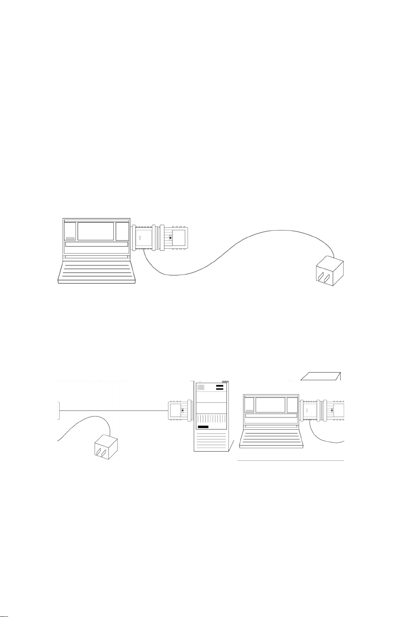
3.0 INSTALLATION
Patton's Model 3P-MF Series are easy to install and should give you
years of trouble-free service. Here are a few simple instructions to help
you get things hooked up right. If y ou hav e an y questions, please contact
Patton Electronics Technical Support at (301)975-1007.
1. Disconnect the short haul modem from the low-power EIA-232
device.
2. Connect Model 3P-MF/3P-MF9 into the DB-25/DB-9 connector of
the short haul modem.
3. Connect the other end of the 3P-MF/3P-MF9 into the EIA-232 device.
The application should look similar to the diagram in Figure 1.
Figure 1.
Connecting a Model 3P-MF
4. Plug the wall-adapter into the AC wall jack.
5. Connect the twisted pair line connection between short haul modems
as described in the short haul modem user manual (see Figure 2,).
Figure 2.
Powering up a Self-Powered Short Haul Modem with a Model 3P-MF
5

PATTON MODEL 3P-MF & 3P-MF9 SPECIFICA TIONS
A PPENDIX A
A.1 TRANSMISSION FORMAT
Asynchronous
A.2 ELECTRICAL INTERFACE
• Model 3P-MF: EIA-232
• Model 3P-MF9: EIA-574
A.3 DATA RATE
Transparent to Data Rate
A.4 DTE/DCE CONNECTION
Either a male or female DB-25
A.5 CONNECTORS
• Model 3P-MF: DB-25M and DB-25F
• Model 3P-MF9P: DB-9M and DB-9F
A.6 POWER SUPPLY
120 or 230 VAC wall mount adapter supplies 9 VDC
A.7 MAX. POWER OUTPUT
+9 VDC ±5% at 100mA (approx 945 mW)
A.8 SIZE
• Model 3P-MF9: 2.7 x 1.2 x 0.7 in. (6.9 x 3.0 x 1.8 cm)
• Model 3P-MF: 2.2 x 2.1 x 0.7 in. (5.6 x 5.3 x 1.8 cm)
A.9 COMPLIANCE INFORMATION
• FCC Part 15, Class A
• UL/CSA (120VDC Wall Mount)
• EN55022 Class A (Emissions)
• EN50082-1 (Immunity)
• 89/336/EEC (Declaration of Conformity—Wall Mount)
• 73/23/EEC (Declaration of Conformity)
6
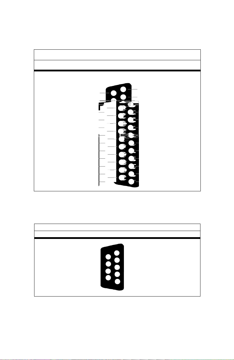
PATTON MODEL 3P-MF & 3P-MF9 PIN ASSIGNMENTS
APPENDIX B
Model 3P-MF DB-25 Interface
SIGNAL/PIN# SIGNAL/PIN#
Secondary Transmit Data - 14
Transmit Clock - 15
Secondary Receive Clock - 16
Receiver Clock - 17
Local Loopback - 18
Secondary Request to Send - 19
Data Terminal Ready - 20
Remote Loopback - 21
Ring Indicator - 22
Data Signal Rate Selector - 23
Transmit Clock - 24
Test Mode - 25
* Note
Model 3P-MF applies power to pin 9 (DCV+) only. All other sig-
1 - (FG) Frame Ground
2 - (TD) Transmit Data
3 - (RD) Receive Data
4 - (RTS) Request to Send
5 - (CTS) Clear to Send
6 - (DSR) Data Set Ready
7 - (SG) Signal Ground
8 - (CD) Carrier Detect
9 - (DCV+) DC Test Voltage*
10 - (DCV-) DC Test Voltage
11 - Unassigned
12 - Secondary Rcvd Line
13 - Secondary Clear to Send
nals are passed through unmodified from end-to-end. Signal
names are provided here to more closely represent the EIA-232
standard (see Appendix C on page 8).
Model 3P-MF9 DB-9 Interface
SIGNAL/PIN# SIGNAL/PIN#
Data Set Ready (DSR) - 6
Ready to Send (RTS) - 7
Clear to Send (CTS) - 8
*DC T est V oltage (DCV+)- 9
1- (CD) Carrier Detect
2 - (RD) Receive Data
3 - (TD) Transmit Data
4- (DTR) Data Terminal Ready
5- (SG/FG) Signal Ground/ Frame Ground
* Note
Model 3P-MF9 applies power to pin 9 (DCV+) only. All other sig-
nals are passed through unmodified from end-to-end. Signal
names are provided here to more closely represent the EIA-232
standard (see Appendix C on page 8).
7

PATTON MODEL 3P-MF BLOCK DIAGRAM
APPENDIX C
8

APPENDIX C - (CONTINUED)
PATTON MODEL 3P-MF9 BLOCK DIAGRAM
Power can be provided through pin 9 (default setting), DSR, or RTS by
changing jumper settings (see Table 1).
Table 1:
Power Output Strap Selection
Jumper Description
JP-1 Connect 9 VDC to male connector (Default setting)
JP-2 Connect 9 VDC to DSR
JP-3 Connect pin 9 of male and female connectors
JP-4 Connect 9 VDC to RTS
9

Dear Valued Customer,
Thank you for purchasing P atton Electronics products! We do appreciate
your business. I trust that you find this user manual helpful.
We manufacture one of the widest selections of data communications
products in the world including CSU/DSU's, network termination units,
powered and self-powered short range modems, fiber optic modems,
interface converters, baluns, electronic data switches, data-line surge
protectors, multiplexers, transceivers, hubs, print servers and much
more. We produce these products at our Gaithersburg, MD, USA, f acility,
and can custom manufacture products for your unique needs.
We would like to hear from y ou. Please contact us in any of the following
ways to tell us how y ou lik e this product and how we can meet your product needs today and in the future.
Web: http://www.patton.com
Sales E-mail: sales@patton.com
Support E-mail: support@patton.com
Phone - Sales (301) 975-1000
Phone - Support (301) 975-1007
Fax: (301) 869-9293
Mail: Patton Electronics Company
7622 Rickenbacker Drive
Gaithersburg, MD 20879 USA
We are committed to a quality product at a quality price. Patton Electronics is BABT and ISO 9001 certified. We meet and exceed the highest
standards in the industry (CE, UL, etc.).
It is our business to serve you. If you are not satisfied with any aspect of
this product or the service provided from Patton Electronics or its distributors, please let us know.
Thank you.
Burton A.Patton
Vice President
P.S. Please tell us where you purchased this product:
_________________________________________________________
_________________________________________________________
_________________________________________________________
_________________________________________________________
10

Notes
_________________________________________________________
_________________________________________________________
_________________________________________________________
_________________________________________________________
_________________________________________________________
_________________________________________________________
_________________________________________________________
_________________________________________________________
_________________________________________________________
_________________________________________________________
_________________________________________________________
_________________________________________________________
_________________________________________________________
_________________________________________________________
_________________________________________________________
_________________________________________________________
_________________________________________________________
_________________________________________________________
_________________________________________________________
_________________________________________________________
_________________________________________________________
Copyright © 1997–2003
Patton Electronics Company
All Rights Reserved.
11
 Loading...