

Page 1
USER
MANUAL
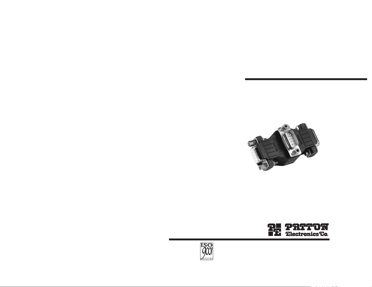
MODEL 3/9 HDX
Multi-Drop
Data Monitoring Tap
SALES OFFICE
(301) 975-1000
TECHNICAL SUPPORT
(301) 975-1007
http://www.patton.com
Part #07M3/9HDX-A
Doc. #100071UA
Revised 6/8/98
CERTIFIED
An ISO-9001
Certified Company
Page 2

1.0 WARRANTY INFORMATION
Patton Electronics warrants all Model 3/9 HDX components to be
free from defects, and will—at our option—repair or replace the product
should it fail within one year from the first date of shipment.
This warranty is limited to defects in workmanship or materials, and
does not cover customer damage, abuse or unauthorized modification.
If this product fails or does not perform as warranted, your sole
recourse shall be repair or replacement as described above. Under no
condition shall Patton Electronics be liable for any damages incurred
by the use of this product. These damages include, but are not limited
to, the following: lost profits, lost savings and incidental or
consequential damages arising from the use of or inability to use this
product. Patton Electronics specifically disclaims all other warranties,
expressed or implied, and the installation or use of this product shall be
deemed an acceptance of these terms by the user.
1.1 CE NOTICE
The CE symbol on your Patton Electronics equipment indicates
that it is in compliance with the Electromagnetic Compatibility (EMC)
directive and the Low Voltage Directive (LVD) of the Union European
(EU). A Certificate of Compliance is available by contacting Patton
Technical Support.
1.2 SERVICE
All warranty and non-warranty repairs must be returned freight
prepaid and insured to Patton Electronics. All returns must have a
Return Materials Authorization number on the outside of the shipping
container. This number may be obtained from Patton Electronics
Technical Service at
tel: (301) 975-1007
email: support@patton.com
www: http:///www.patton.com
NOTE:
Packages received without an RMA number will not be
accepted.
Patton Electronics' technical staff is also available to answer any
questions that might arise concerning the installation or use of your
Model 3/9 HDX. Technical Service hours: 8AM to 5PM EST, Monday
through Friday.
1
2.0 GENERAL INFORMATION
Thank you for your purchase of this Patton Electronics product. If
any questions or problems arise during installation or use of this
product, please do not hesitate to contact Patton Electronics Technical
Support at (301) 975-1007.
2.1 FEATURES
• Allows EIA-574/RS-232 Data Monitoring
• Monitoring Equipment Attaches to DB-9 Tap Connector
• Tap Connector Side OR Gate allows monitoring of TD and RD
Lines in a Half-Duplex Environment
• Supports data rates up to 115,200 bps
• EMC Compliance: FCC Part 15, Class A and Directive
89/336/EEC using Standard: EN55022 for ITE
2.2 DESCRIPTION
The Model 3/9 HDX Multi-Drop Data Monitoring Tapallows you
to monitor data line activity in half-duplex applications without tying up
valuable oscilloscopes or protocol analyzers. Use it to tap into
industrial control or other multi-point polling applications. All you need
is a terminal running monitoring software.
Two of Model 3/9 HDX’s three DB-9 connectors are wired
straight-
through
with all 9 pins. The Tap connector’s OR gate circuitry
combines TD or RD on to a single line to allow monitoring of both
signals. Available in all gender combinations, Model 3/9 HDX is a must
for a network technician’s toolbox.
2
Page 3

3.0 INSTALLATION
The Model 3/9 HDX requires no configuration prior to, or
subsequent to, installation: It is strictly "plug and play". This section
tells how to install the Model 3/9 HDX in a half-duplex application.
3.1 CONNECTING THE INTERFACE PORTS
Model 3/9 HDX is designed to plug directly between DTE and DCE
devices with a monitoring device connected to the DB-9 “Tap”
connector.
In a typical data acquisition (DAQ) or process control half-duplex*
application, (see Figure 1, below) only one device communicates on the
data bus at a time. By connecting a monitor to the “Tap” side of Model
3/9 HDX, you can independently monitor both directions (TD and RD pins 3 and 2, respectively) of the data bus without interrupting data flow.
*NOTE: Model 3/9 HDX will not work in full-duplex applications.
Follow the instructions below to make install the 3/9 HDX.
1. Disconnect the cable from the master device. Verify all DB-9
pin connections. NOTE: Pins 3 and 2 are connected through
an OR gate to the tap connector. All other pins are wired
straight-through
(See Appendix B for Pin Assignments).
2. Connect the master device into the “A” port of Model 3/9 HDX.
3. Connect the bus cable into the “B” port of Model 3/9 HDX.
4. Connect the monitoring equipment to the DB-9 tap connector.
5. Resume operations while monitoring data and control signal
activity.
3 4
Figure 1. Typical Application of Model 3/9 HDX in Half Duplex Environment
APPENDIX A
SPECIFICATIONS
Data Rates: Up to 115,200 bps
Transmission Format: Asynchronous or synchronous
Transmission Mode: Half duplex
Interface: EIA-574
Connectors: DB9 Male or Female on all ports (All Configurations
Available: MF-F, MF-M, MM-F, MM-M, FF-F, FF-M
Power: Derived from RS-232 data and control signals, no AC power or
batteries required
Temperature Range: 0-50
°
C (32-122°F)
Humidity: Up to 95% non-condensing
Host
Computer
Model 3-9 HDX
Monitor
DAQ Equipment
Page 4

APPENDIX C
BLOCK DIAGRAM
6
APPENDIX B
EIA-574 PIN CONFIGURATIONS
5
1- (CD) Data Carrier Detect To DTE
2- (RD) Receive Data To DTE
3- (TD) Transmit Data From DTE
4- (DTR)Data Terminal Ready From DTE
5- (SG) Signal Ground -
To DTE Data Set Ready (DSR) - 6
From DCE Request To Send (RTS) - 7
To DTE Clear to Send (CTS) - 8
DIRECTION STANDARD "DCE" CONFIGURATION DIRECTION
 Loading...