

Page 1
Model 3324
VDSL Carrier-Class Aggregator
Getting Started Guide
Sales Office: +1 (301) 975-1000
Technical Support: +1 (301) 975-1007
E-mail: support@patton.com
WWW: www.patton.com
Document Number: 05813U1-001 Rev. A
Part Number: 07MD3324-GSG
Revised: May 21, 2004
Page 2

Patton Electronics Company, Inc.
7622 Rickenbacker Drive
Gaithersburg, MD 20879 USA
tel: +1 (301) 975-1000
fax: +1 (301) 869-9293
support: +1 (301) 975-1007
web: www.patton.com
e-mail: support@patton.com
Copyright © 2003, Patton Electronics Company. All rights reserved.
The information in this document is subject to change without notice. Patton Electronics assumes no liability for errors that may appear in this document.
Page 3

Contents
Contents ......................................................................................................................................................... 3
Compliance Information ................................................................................................................................ 7
Radio and TV interference ................................................................................................................................7
CE Notice .........................................................................................................................................................7
Service ..............................................................................................................................................................7
About this guide ............................................................................................................................................. 9
Audience................................................................................................................................................................. 9
Structure................................................................................................................................................................. 9
Precautions ............................................................................................................................................................. 9
Safety when working with electricity ...............................................................................................................10
Preventing electrostatic discharge damage .......................................................................................................10
General observations .......................................................................................................................................11
Typographical conventions used in this document................................................................................................ 11
General conventions .......................................................................................................................................11
Mouse conventions .........................................................................................................................................12
1 General Information...................................................................................................................................... 13
Model 3324 overview ............................................................................................................................................14
Hardware overview................................................................................................................................................15
Ethernet uplink ...............................................................................................................................................16
POTS/ISDN ..................................................................................................................................................16
VDSL ports ....................................................................................................................................................17
RS-232 control port ........................................................................................................................................17
Power system ..................................................................................................................................................17
Management services ......................................................................................................................................17
LED display ....................................................................................................................................................17
Approvals ..............................................................................................................................................................18
2 Hardware installation.................................................................................................................................... 19
Introduction..........................................................................................................................................................20
Unpacking the Model 3324...................................................................................................................................20
Model 3324 chassis installation .............................................................................................................................20
Cable installation...................................................................................................................................................21
Installing the power cables—AC power supply ...............................................................................................21
Connecting the Ethernet uplink ports .............................................................................................................21
Cascading configuration ............................................................................................................................22
Optional GBIC Ethernet uplink slot ...............................................................................................................24
GBIC fiber optics ............................................................................................................................................24
Connecting the EIA-574, RS-232 configuration port (DCE configured) ........................................................24
Connecting the POTS/ISDN Ports ................................................................................................................25
Connecting the VDSL Ports ...........................................................................................................................25
Completing the hardware installation....................................................................................................................26
3
Page 4

Contents
Model 3324 User Guide
3 Configuring the 3324 for operation.............................................................................................................. 27
Introduction..........................................................................................................................................................29
Configuration prerequisites ...................................................................................................................................29
Initial configuration through the RS-232 control port...........................................................................................30
Connecting the DB9-RJ45 adapter with the included cable ............................................................................30
Setting up the HyperTerminal (or similar program) session ............................................................................30
Set IP address ..................................................................................................................................................33
Remote Network Management..............................................................................................................................35
Controlling the Model 3324 remotely through TELNET ...............................................................................35
Controlling the Model 3324 remotely through SNMP ...................................................................................35
Port Status ......................................................................................................................................................36
State ..........................................................................................................................................................36
Link Status ................................................................................................................................................36
SNR (Signal to Noise Ratio) .....................................................................................................................36
Speed Status ..............................................................................................................................................37
Duplex Status ............................................................................................................................................37
Flow Control .............................................................................................................................................37
Rate Control .............................................................................................................................................37
Port Security .............................................................................................................................................37
Port Statistics ..................................................................................................................................................38
Administrator ........................................................................................................................................................38
IP Address Configuration ................................................................................................................................39
Basic Switch Settings .......................................................................................................................................39
Description ...............................................................................................................................................39
MAC Address ............................................................................................................................................39
Firmware Version ......................................................................................................................................39
Default Config Value Version ...................................................................................................................39
Advanced Switch Settings ...............................................................................................................................39
Mac Address Age-out Time .......................................................................................................................39
Max Bridge Transit Delay Bound Control ................................................................................................40
Broadcast Storm Filter ...............................................................................................................................40
Priority Queue Service Settings .......................................................................................................................40
First Come First Service ............................................................................................................................40
All High Before Low .................................................................................................................................40
WRR (Weighted Round-Robin) ...............................................................................................................40
Enable Delay Bound .................................................................................................................................41
QoS Policy High Priority Levels ................................................................................................................41
Protocol Enable Settings .................................................................................................................................41
Enable STP ...............................................................................................................................................41
Enable IGMP ............................................................................................................................................41
Console Port Settings ......................................................................................................................................41
Port Control Settings ......................................................................................................................................42
State ..........................................................................................................................................................42
Negotiation ...............................................................................................................................................42
4
Page 5

5
Model 3324 User Guide
Speed ........................................................................................................................................................42
Link Watch Dog(LWD) function: ......................................................................................................42
Procedure for Changing VDSL Ports Speed Settings: .........................................................................42
Rate Control .............................................................................................................................................43
Port Security .............................................................................................................................................43
Duplex ......................................................................................................................................................43
Flow Control .............................................................................................................................................44
Trunking ........................................................................................................................................................44
System Priority ..........................................................................................................................................44
State Activity .............................................................................................................................................46
Filter Database ................................................................................................................................................46
IGMP Snooping .......................................................................................................................................46
Static MAC Address ........................................................................................................................................47
MAC Filtering ................................................................................................................................................48
VLAN Configurations ....................................................................................................................................48
Support Port-based VLAN ........................................................................................................................49
Tagged-based VLAN .................................................................................................................................50
Port VID ...................................................................................................................................................53
Ingress Filtering ..............................................................................................................................................53
Spanning Tree Protocol Settings .....................................................................................................................53
Port Sniffer .....................................................................................................................................................55
SNMP Settings ...............................................................................................................................................56
Security Manager ......................................................................................................................................57
System Configuration (802.1X) ......................................................................................................................57
Per port Configuration ..............................................................................................................................58
Misc. Configuration ..................................................................................................................................58
TFTP Update Firmware .................................................................................................................................58
Using TFTP ...................................................................................................................................................59
TFTP Restore Configuration ....................................................................................................................59
TFTP Backup Configuration ....................................................................................................................60
Resetting the Model 3324 ...............................................................................................................................60
Rebooting the Model 3324 .............................................................................................................................60
Contents
4 Applications .................................................................................................................................................. 61
MxU multi-service delivery....................................................................................................................................62
High bandwidth backbone ....................................................................................................................................63
5 Troubleshooting............................................................................................................................................ 65
Diagnosing VDSL indicators.................................................................................................................................66
System Diagnostics................................................................................................................................................66
Power and Cooling Problems ..........................................................................................................................66
Installation ............................................................................................................................................................67
Transmission Mode ........................................................................................................................................67
Cabling ...........................................................................................................................................................67
Physical Configuration ....................................................................................................................................67
Page 6

Contents
Model 3324 User Guide
System Integrity ..............................................................................................................................................67
CPE (Customer Premise/Remote) Side Starts Link Watch Dog ............................................................................67
6 Contacting Patton for assistance ................................................................................................................... 69
Introduction..........................................................................................................................................................70
Contact information..............................................................................................................................................70
Warranty Service and Returned Merchandise Authorizations (RMAs)...................................................................70
Warranty coverage ..........................................................................................................................................70
Out-of-warranty service .............................................................................................................................70
Returns for credit ......................................................................................................................................70
Return for credit policy .............................................................................................................................71
RMA numbers ................................................................................................................................................71
Shipping instructions ................................................................................................................................71
A Specifications ................................................................................................................................................ 73
VDSL line interface...............................................................................................................................................75
POTS-ISDN interface...........................................................................................................................................75
Modulation ...........................................................................................................................................................75
Frequency range ....................................................................................................................................................75
Transmission .........................................................................................................................................................75
Management .........................................................................................................................................................75
Ethernet standards.................................................................................................................................................75
Management standards..........................................................................................................................................75
LED indicators......................................................................................................................................................75
Power supply .........................................................................................................................................................75
Compliance ...........................................................................................................................................................75
Environment .........................................................................................................................................................75
Operating temperature ....................................................................................................................................75
Humidity ........................................................................................................................................................76
Dimensions ...........................................................................................................................................................76
Weight ..................................................................................................................................................................76
B Cabling ......................................................................................................................................................... 77
Introduction..........................................................................................................................................................78
C VDSL Spectrum ........................................................................................................................................... 81
Introduction..........................................................................................................................................................82
D Example of VLAN Setting ............................................................................................................................ 83
Introduction..........................................................................................................................................................84
6
Page 7

Compliance Information
and TV
Radio
The Model 3324 generates and uses radio frequency energy, and if not installed and used properly—that is, in
strict accordance with the manufacturer's instructions—may cause interference to radio and television reception. The Model 3324 has been tested and found to comply with the limits for a Class A computing device in
accordance with the specifications in Subpart B of Part 15 of FCC rules, which are designed to provide reasonable protection from such interference in a commercial installation. However, there is no guarantee that interference will not occur in a particular installation. If the Model 3324 does cause interference to radio or
television reception, which can be determined by disconnecting the cables, the user is encouraged to try to correct the interference by one or more of the following measures: moving the computing equipment away from
the receiver, re-orienting the receiving antenna, and/or plugging the receiving equipment into a different AC
outlet (such that the computing equipment and receiver are on different branches).
CE Notice
The CE symbol on your Patton Electronics equipment indicates that it is in compliance with the Electromagnetic Compatibility (EMC) directive and the Low Voltage Directive (LVD) of the Union European (EU). A
Certificate of Compliance is available by contacting Technical Support.
Service
All warranty and non-warranty repairs must be returned freight prepaid and insured to Patton Electronics. All
returns must have a Return Materials Authorization number on the outside of the shipping container. This
number may be obtained from Patton Electronics Technical Services at:
• Tel: +1 (301) 975-1007
interference
• Email: support@patton.com
• URL: www.patton.com
Note
Packages received without an RMA number will not be accepted.
7
Page 8

8
Compliance Information
Model 3324 User Guide
Page 9
About this guide
This guide describes installing and configuring a Patton Electronics Model 3324 VDSL Carrier Class Aggregator. By the time you are finished with this guide, your Model 3324 will be connected to the remote VDSL
modems and transferring data. The instructions in this guide are based on the following assumptions:
• The Model 3324 will connect to an 10/100/1000Base-TX Network Uplink or Device
• There is a LAN connected to the Ethernet port of the 3324
• Users will be connected to remote VDSL modems.
Audience
This guide is intended for the following users:
• Operators
• Installers
• Maintenance technicians
Structure
This guide contains the following chapters and appendices:
• Chapter 1 describes the 3324
• Chapter 2 describes installing the 3324 hardware
• Chapter 3 describes configuring the 3324 for use
• Chapter 4 describes Model 3324 applications
• Chapter 5 contains troubleshooting information
• Chapter 6 contains information on contacting Patton technical support for assistance
For best results, read the contents of this guide before you install the router.
Precautions
Notes and cautions, which have the following meanings, are used throughout this guide to help you become
aware of potential Router problems. Warnings relate to personal injury issues, and Cautions refer to potential
property damage.
Note
Calls attention to important information.
The shock hazard symbol and WARNING heading indicate a potential electric
shock hazard. Strictly follow the warning instructions to avoid injury caused
by electric shock.
The alert symbol and WARNING heading indicate a potential safety hazard.
Strictly follow the warning instructions to avoid personal injury.
9
Page 10
About this guide
The shock hazard symbol and CAUTION heading indicate a
potential electric shock hazard. Strictly follow the instructions to
avoid property damage caused by electric shock.
The alert symbol and CAUTION heading indicate a potential
hazard. Strictly follow the instructions to avoid property damage.
Safety when working with electricity
Mains Voltage: Do not open the case when the power cord is connected. For
systems without a power switch, line voltages are present within the power
supply when the power cord is connected.
Hazardous network voltages are present in WAN ports regardless of whether
power to the SmartNode is ON or OFF. To avoid electric shock, use caution
when near WAN ports. When detaching cables, detach the end away from the
SmartNode first.
Model 3324 User Guide
Do not work on the system or connect or disconnect cables during periods of
lightning activity.
Before opening the chassis, disconnect the telephone network
cables to avoid contact with telephone line voltages.
Ultimate disposal of this equipment must be handled according
to all applicable national laws and regulations.
Preventing electrostatic discharge damage
When starting to install interface cards place the interface card on its shielded plastic bag if you lay it on your
bench.
10
Page 11
11
Model 3324 User Guide
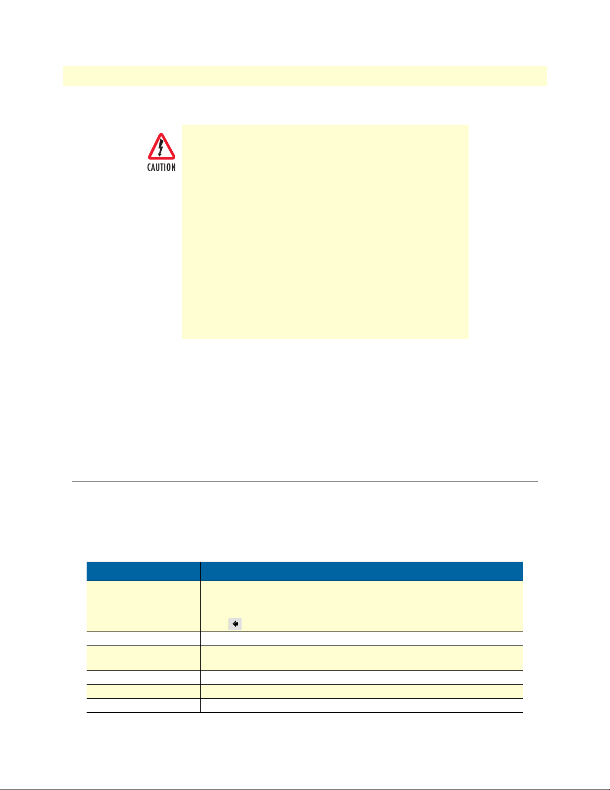
Electrostatic Discharge (ESD) can damage equipment and impair
electrical circuitry. It occurs when electronic printed circuit cards
are improperly handled and can result in complete or intermittent failures. Do the following to prevent ESD:
Always follow ESD prevention procedures when removing
•
and replacing cards.
•
Ensure that the SmartNode chassis is electrically connected to
earth ground.
•
Wear an ESD-preventive wrist strap, ensuring that it makes
good skin contact. Connect the clip to an unpainted surface
of the chassis frame to safely channel unwanted ESD voltages
to ground.
•
To properly guard against ESD damage and shocks, the wrist
strap and cord must operate effectively. If no wrist strap is
available, ground yourself by touching the metal part of the
chassis.
About this guide
General observations
• Clean the case with a soft slightly moist anti-static cloth
• Place the unit on a flat surface (or optionally in a rack for the SN2x00) and ensure free air circulation
• Avoid exposing the unit to direct sunlight and other heat sources
• Protect the unit from moisture, vapors, and aggressive liquids
Typographical conventions used in this document
This section describes the typographical conventions and terms used in this guide.
General conventions
The procedures described in this manual use the following text conventions:
Table 1. General conventions
Convention Meaning
Garamond blue type
Futura bold type Commands and keywords are in boldface font.
Futura bold-italic type Parts of commands, which are related to elements already named by the user, are
Italicized Futura type
Futura type Indicates the names of fields or windows.
Garamond bold type Indicates the names of command buttons that execute an action.
Indicates a cross-reference hyperlink that points to a figure, graphic, table, or section heading. Clicking on the hyperlink jumps you to the reference. When you
have finished reviewing the reference, click on the Go to Previous View
button in the Adobe® Acrobat® Reader toolbar to return to your starting point.
in
boldface italic
Variables for which you supply values are in
font.
italic
font
Page 12
About this guide
Model 3324 User Guide
Table 1. General conventions
Convention Meaning
< >
[ ] Elements in square brackets are optional.
{a | b | c} Alternative but required keywords are grouped in braces ({ }) and are separated
blue screen Information you enter is in blue screen font.
screen Terminal sessions and information the system displays are in screen font .
node The leading IP address or nodename of a SmartNode is substituted with
SN The leading SN on a command line represents the nodename of the SmartNode
# An hash sign at the beginning of a line indicates a comment line.
Angle brackets indicate function and keyboard keys, such as <SHIFT>, <CTRL>,
<C>, and so on.
by vertical bars ( | )
boldface italic
font.
Mouse conventions
The following conventions are used when describing mouse actions:
Table 2. Mouse conventions
Convention Meaning
Left mouse button
Right mouse button This button refers the secondary or rightmost mouse button (unless you have
Point This word means to move the mouse in such a way that the tip of the pointing
Click Means to press and release the left or right mouse button one time quickly (as
Double-click Means to press and release the same mouse button two times quickly. Make sure
Drag This word means to place the cursor and then hold down the left or right mouse
This button refers to the primary or leftmost mouse button (unless you have
changed the default configuration).
changed the default configuration).
arrow (referred to as the
tion.
instructed in the procedure). Make sure you do not move the cursor while clicking
a mouse button.
you do not move the cursor while clicking a mouse button.
button (as instructed in the procedure) as you move the mouse to a new location.
When you have moved the cursor to the desired location, you can release the
mouse button.
cursor
) on the screen ends up resting at the desired loca-
node
in
12
Page 13

Chapter 1
Chapter contents
Model 3324 overview ............................................................................................................................................14
Hardware overview................................................................................................................................................15
Ethernet uplink ...............................................................................................................................................16
POTS/ISDN ..................................................................................................................................................16
VDSL ports ....................................................................................................................................................17
RS-232 control port ........................................................................................................................................17
Power system ..................................................................................................................................................17
Management services ......................................................................................................................................17
LED display ....................................................................................................................................................17
Approvals ..............................................................................................................................................................18
General Information
13
Page 14
14
1 • General Information
Model 3324 User Guide
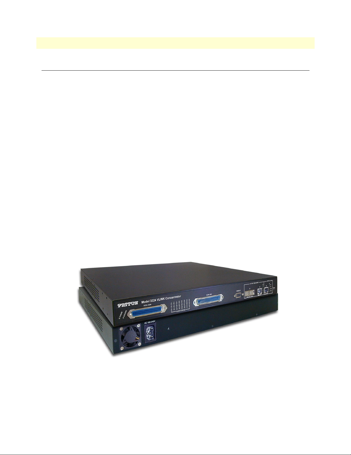
Model 3324 overview
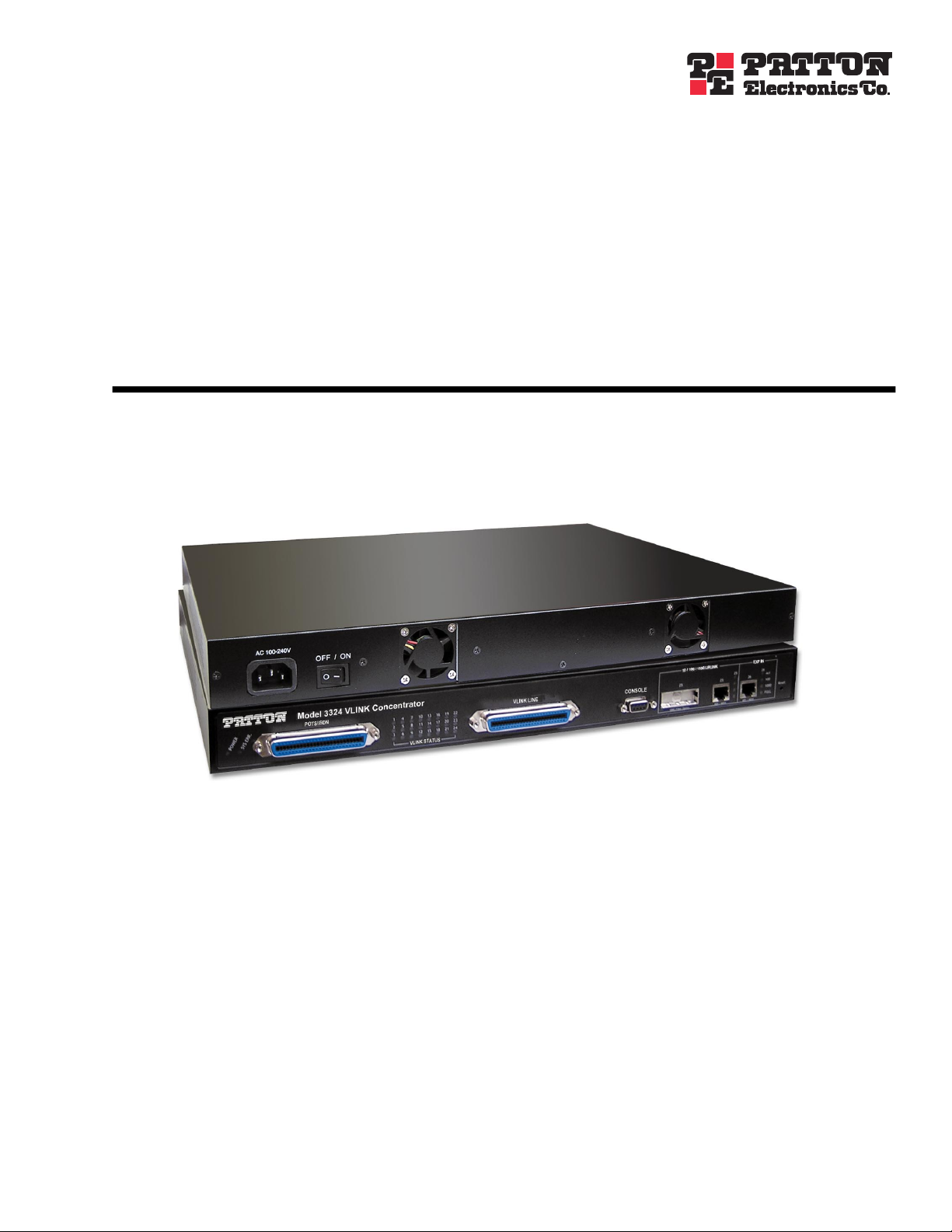
The Patton Model 3324 VDSL (see figure 1) networking solution delivers cost-effective, high-performance
broadband access to multi-unit buildings (hotels, apartments, and multi-tenant unit office buildings) and
enterprise campus environments such as factories, educational campuses, and medical facilities. VDSL technology dramatically extends Ethernet over existing Category 1, 2, or 3 wiring at speeds from 5, 10, or 15 Mbps
(full duplex) and distances up to 4,921, 3,937, or 3,281 feet (1,500, 1,200, or 1,000 meters). The Model 2234
delivers broadband service on the same infrastructure as plain old telephone service (POTS), digital telephone
service, and ISDN service. In addition, VDSL supports modes compatible with symmetric digital subscriber
line, allowing service providers to provision VDSL to buildings where broadband services may already exist.
The VDSL solution includes Patton Model 3324 (VDSL Access Concentrator), and Model 1058/CP (VDSL
Customer Premise Modem).
The VDSL solution delivers everything needed to quickly deploy an Ethernet-based network with the performance required to deliver high-speed Internet access at much greater distances and drive services like IP telephony and audio/video streaming. With this technology, a broad range of customers can benefit from lower
operating Costs and rapid deployment. The VDSL solution provides multicast, Layer 2 quality of service
(QoS), Link Aggregation (LACP) dynamic trunking groups, security, GVRP, IGMP for VOD (Video on
demand) and SNMP RMON management and Web-based Switch network management.
The Patton Model 3324 is a bridge between external Internet backbone through a router for IP sharing and the
building 110D telephone rack or telephone box. It utilizes the available telephone wire to enable high-speed
Internet access to building’s residents. The Patton Model 3324 uses the phone line networking technology
endorsed by the VDSL (Very High Data Rate DSL), and the 3324 utilizes already existing telephone wire to
deliver 5/10/15 Mbps Internet access on each RJ-21 port. This gives users a low-cost, end-to-end solution that
eliminates the need to train installation teams on multiple systems.
Figure 1. Model 3324 Carrier-Class Aggregator
Model 3324 overview
Page 15
Model 3324 User Guide 1 • General Information
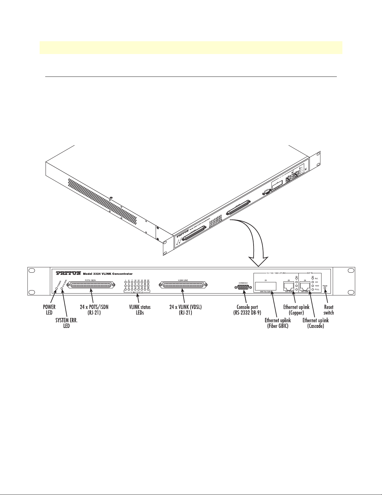
Hardware overview
The Model 3324 combines networking and voice services by concentrating 24 x VDSL (Network) and 24 x
POTS/ISDN ports for transport over a single phone grade twisted pair in a single 1U managed chassis. The
3324 (see figure 2 and figure 3 on page 16) comprises a 1U-high 19-inch wide chassis that contains a motherboard and on-board POTS/ISDN splitter and an AC power supply. A full set of LEDs are present on the chassis front panel along with all electrical connections. This makes both quick status checks and network
connections a snap. LEDs are present to monitor the Ethernet uplink link and activity, VDSL link and activity,
and power connections. One IEC-320 receptacle is provided for AC power input.
Figure 2. Model 3324 front panel connectors and LEDs
Hardware overview 15
Page 16
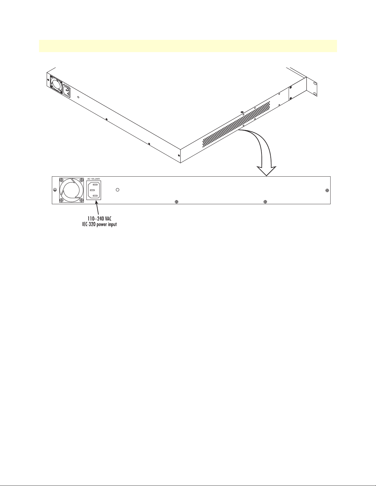
1 • General Information Model 3324 User Guide
Figure 3. Model 3324 rear panel power input connector
Ethernet uplink
The Model 3324 includes two Ethernet uplink ports. Uplink connections can be made either through the
Ethernet GBIC (fiber connection) or via RJ-45 (copper connection)
Also included are:
• One Ethernet expansion slot for cascading up to four Model 3324’s
• Auto-sensing 10/100/1000Base-TX full or half-duplex
• Auto MDI-X
• Link and activity indicators
POTS/ISDN
The Model 3324 includes one RJ-21 connector for up to 24 POTS/ISDN connections.
Also included are:
• >>>>>>>>>>>>>>>>
• >>>>>>>>>>>>>>>
16 Hardware overview
Page 17

Model 3324 User Guide 1 • General Information
VDSL ports
The 24 VDSL ports operate at data-rates up to 15 Mbps symmetrical and are accessible via the RJ-21X 50-pin
telco connector. Each port uses one twisted-pair (2-wires) for symmetrical communication. The VDSL ports
concentrate the POTS/ISDN (voice) and data into one output on the VDSL ports. Other features include:
• QAM line encoding
• "Plug-and-Play" automatic configuration between the Model 3324 VDSL aggregator and the VDSL
CPE modems
• Built-in surge protection
• VDSL configuration parameters and line status indicators
• Bandwidth management (speed rate control) from 100 kbps to 5/10/15 Mbps
• Signal-to-noise ratio (SNR) for checking wiring quality and cross talk
RS-232 control port
The RS-232 port provides for initial configuration of the Model 3324. The RS-232 port supports:
• Asynchronous data rate of 9600kbps, 8 data bits, no parity, 1 stop bit, flow control none.
• An DB9 connector
• A management interface that supports VT-100 terminals
Power system
Universal-input voltage range, 100–240 VAC, 50/60 Hz via IEC-320 connectors
Management services
• Out-of-band RS-232 configuration port for management and control
• SNMP version 1 configuration management
• MIB II
• TELNET Ethernet
• Remote software upgrade via FTP/TFTP
• Built-in HTTP server for complete configuration and control using a standard Web browser
LED display
LEDs are present to monitor the Ethernet Uplink Link and Activity, VDSL Link and Activity, and Power connections.
• POWER: Green LED is ON if power is being applied. If power is lost the green LED is OFF
• POST (power on self test): If LED is steady green Model 3324 is self-testing
• ACT (Receiving LEDs): LED flashes green when receiving or transmitting data
• Speed 100/Speed 1000: Steady yellow indicates communications have been set at 100 or 1000 Mbps
Hardware overview 17
Page 18

1 • General Information Model 3324 User Guide
• FD: Steady yellow if working at full-duplex, OFF if working at half-duplex
• LINK: Steady green when the Model 3324 and CP has established a link, OFF when link is down
Approvals
The Model 3324 has achieved the following approvals and certifications:
• Safety
- UL1950 (MET)
- Industry Canada (cMET)
• RTTE Directive (CE Mark)
- EMC Directive 89/336/EEC
- Low Voltage Directive 73/23/EEC (EN 60950)
- ITU-T CTR 12
- ITU-T CTR 13
• EMC
- FCC Part 15, Subpart B, Class A
• Telecom
- FCC Part 68
- Industry Canada
18 Approvals
Page 19

Chapter 2 Hardware installation
Chapter contents
Introduction..........................................................................................................................................................20
Unpacking the Model 3324...................................................................................................................................20
Model 3324 chassis installation .............................................................................................................................20
Cable installation...................................................................................................................................................21
Installing the power cables—AC power supply ...............................................................................................21
Connecting the Ethernet uplink ports .............................................................................................................21
Cascading configuration ............................................................................................................................22
Optional GBIC Ethernet uplink slot ...............................................................................................................24
GBIC fiber optics ............................................................................................................................................24
Connecting the EIA-574, RS-232 configuration port (DCE configured) ........................................................24
Connecting the POTS/ISDN Ports ................................................................................................................25
Connecting the VDSL Ports ...........................................................................................................................25
Completing the hardware installation....................................................................................................................26
19
Page 20

2 • Hardware installation Model 3324 User Guide
Introduction
This chapter contains the following procedures for installing the Model 3324:
• “Unpacking the Model 3324”—lists the contents in the Model 3324 shipping container
• “Model 3324 chassis installation”—describes installing the Model 3324 on a flat surface or in a standard
19-inch rack
• “Cable installation” on page 21—describes installing the power and network interface cables
• “Completing the hardware installation” on page 26—describes testing the Model 3324 hardware to verify
that it is ready for software configuration
Unpacking the Model 3324
Inspect the shipping carton for external damage. Note any damage before removing the container contents.
Report equipment damage to the shipping carrier immediately for claim purposes. Save all packing materials in
case you need to return an item to the factory for servicing.
The Model 3324 comes with the following items:
• The Model 3324 VDSL Carrier Class Aggregator
• Install kit
- 2 DB9-RJ45 (EIA-561) adapters, one to connect to the Model 3324 and one to connect to PC serial port
- 1 RJ-45-to-RJ-45 cable to connect between the two adapters
• 2 Rack mounting brackets
• 4 Screws
• 4 Plastic feet
• Model 3324 VDSL Carrier-Class Aggregator User Guide on CD-ROM
Note Power cables are shipped separately from the Model 3324 DACS.
You will need two 5-foot (1.5-meter) RJ-21 male-to-male Telco connector cables.
Model 3324 chassis installation
Do the following:
1. If you have not done so already, remove the Model 3324 from its shipping container.
Note The Model 3324 should be placed as close as possible to the termina-
tion jack provided by the Telco. Avoid installing the Model 3324 in a
location where the power cords or network interface cables could be
accidentally disconnected. The location should be well ventilated, dry,
and not in direct sunlight. Do not block the Model 3324 cooling fans.
2. If you are installing the Model 3324 in a 19-inch rack, go to step 3. Otherwise, place the Model 3324 at
the desired location, then go to “Cable installation” on page 21.
20 Introduction
Page 21

Model 3324 User Guide 2 • Hardware installation
3. Install the rack mounting ears onto the Model 3324 using the mounting hardware provided.
4. Place the Model 3324 at the desired position in the rack.
5. Secure the Model 3324 in position with the mounting screws.
Cable installation
This section describes installing the power, ground, and network interface cables.
Installing the power cables—AC power supply
This section describes installing the power cables into the IEC-320 connectors on the DACS. Do not connect
the male end of the power cables to the power outlet at this time. Do the following:
1. Install a power cable into an IEC-320 connector (see figure 3 on page 16). The AC main socket outlet
shall be within 10 feet (3 meters) of the equipment and shall be easily accessible.
Connecting the Ethernet uplink ports
The Model 3324 has two auto-negotiating 10/100/1000Base-TX Ethernet interfaces that support full or halfduplex operation. The devices attached to these ports also must support auto-negotiation unless they always
operate at half-duplex. Both ports feature auto MDI-X.
Note Make sure the Ethernet CAT-5 cable is not longer than 328 feet
(100 meters).
Ethernet uplink port #25 is used to connect to devices such as servers, routers, or switches. Port #25 is your primary
uplink (your connection to the service provider). Port #26 is used for cascading up to four Model 3324s together.
Port #25 and port #26 will auto-sense the correct speed of the local LAN and automatically negotiate half- or fullduplex operation.
Cable installation 21
Page 22
2 • Hardware installation Model 3324 User Guide
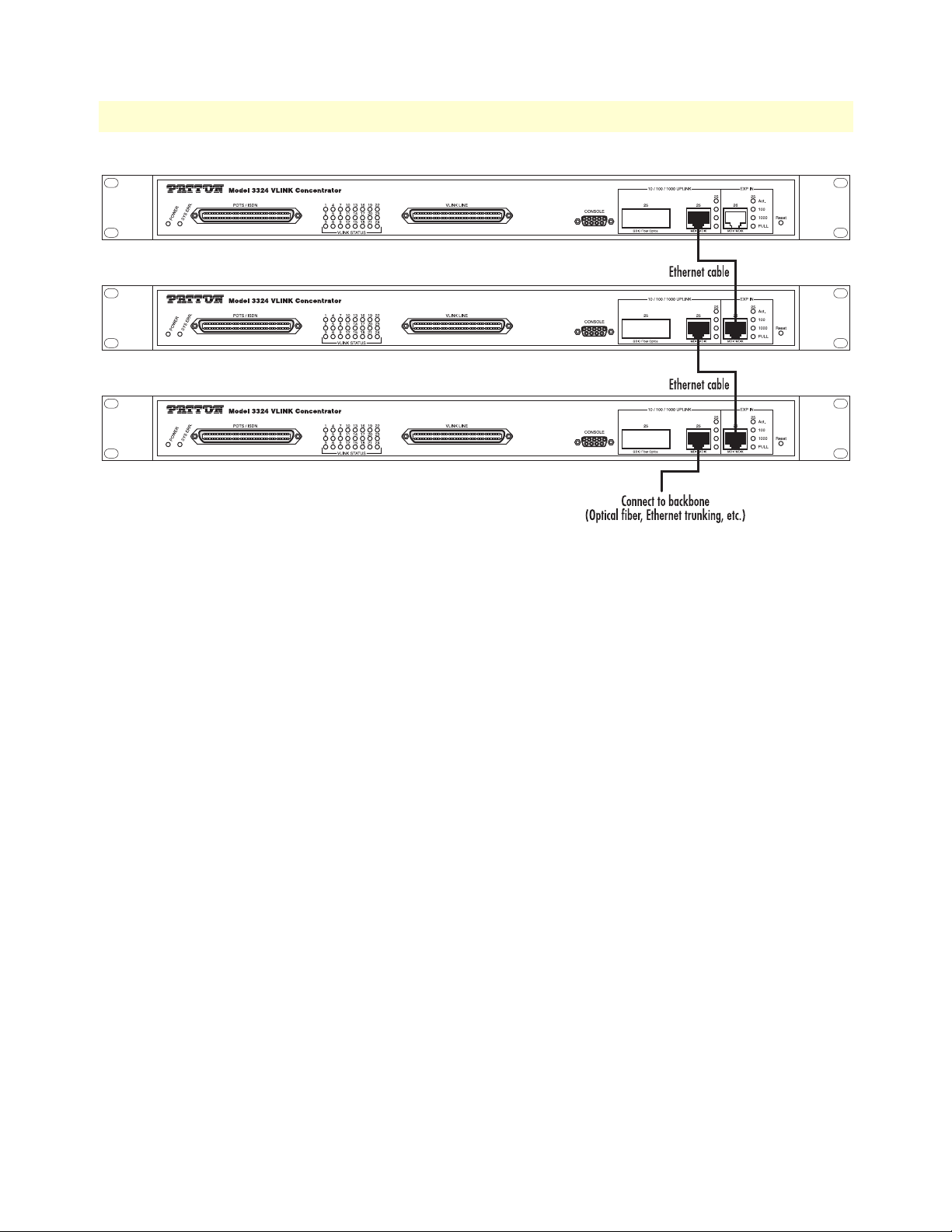
Figure 4. Cascading configuration
Cascading configuration
When cascading more than two Model 3324s (see figure 4), the default settings are set to full duplex, and 1000
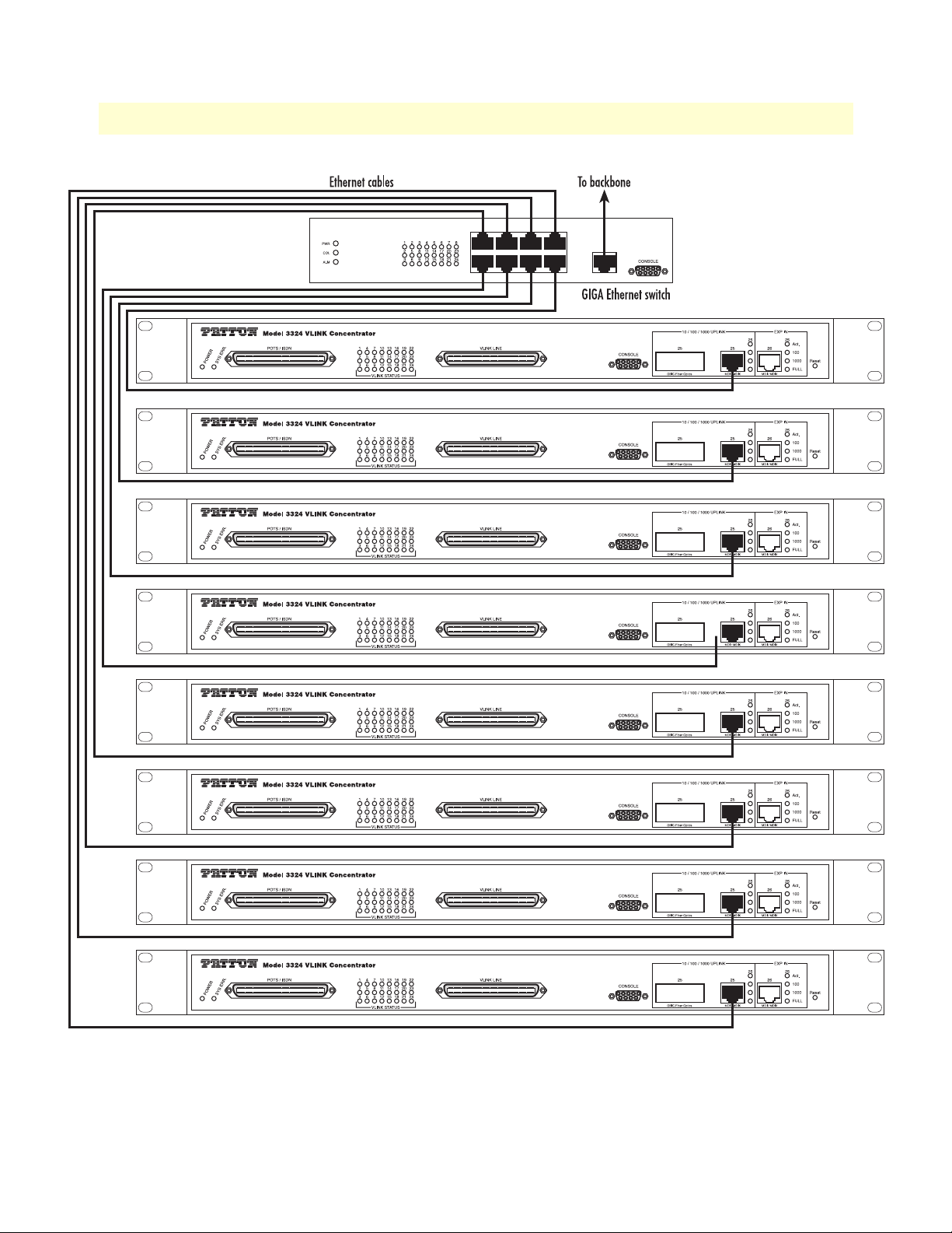
Mbps via the daisy-chain port. The maximum number of Model 3324s that can be cascaded is four units. If
more than four units must be cascaded, an Ethernet switch will be required (see configuration example shown
in figure 5 on page 23).
22 Cable installation
Page 23
Model 3324 User Guide 2 • Hardware installation
Figure 5. Cascade configuration using Ethernet switch
Cable installation 23
Page 24
2 • Hardware installation Model 3324 User Guide
Optional GBIC Ethernet uplink slot
The Model 3324 supports the use of one GBIC interface auto-link function. Normal Ethernet uplink port status default is copper (RJ-45), but you can use the hot-swap capability—modules can be exchanged without
turning off power—of the Model 3324 to quickly change the uplink media to fiber.
GBIC fiber optics
A gigabit interface converter (GBIC) is a transceiver that converts electric currents (digital highs and lows) to optical signals, and optical signals to digital electric currents. The GBIC is typically employed in fiber optic and Ethernet systems as an interface for high-speed networking. The data transfer rate is 1.25 gigabits per second (Gbps).
GBIC modules enable technicians to easily configure and upgrade electro-optical communications networks.
The typical GBIC transceiver is a plug-in module that supports hot-plugging. The devices are economical,
because they eliminate the necessity for replacing entire boards at the system level. Upgrading can be done with
any number of units at a time, from an individual module to all the modules in a system. GBIC is compliant
with the Gigabit Interface Converter Specification, Rev. 5.4 (MOD_DEF4) industry standard.
Mode Wavelength Bit Rate Voltage Power Margin
1 LX-Single Mode 1310 nm 1.25 Gbps 5V 10.5 dB (6 miles/10 km)
2 SX-Multi Mode 850 nm 1.25 Gbps 5V 8.5 dB (1800 feet/550 m)
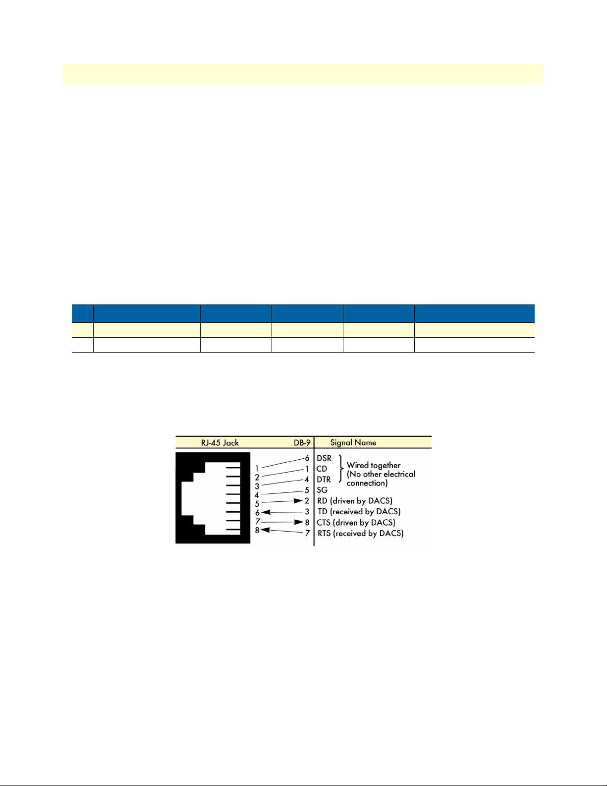
Connecting the EIA-574, RS-232 configuration port (DCE configured)
Install the supplied RJ-45-to-RJ-45 cable between the (2) DB9-RJ45 adapter and the RS-232 port (see figure 2
on page 15) and an open serial port on your computer. If you need to assemble your own cable, refer to the
pinout diagram in figure 6.
Figure 6. DB-9-to-RJ-45 cable diagram
24 Cable installation
Page 25

Model 3324 User Guide 2 • Hardware installation
Connecting the POTS/ISDN Ports
The remote (customer premise) VDSL modems will receive there POTS/ISDN connections from the Model
3324 via the VDSL twisted pair. The POTS/ISDN services from a PBX are connected into the 3324 via a RJ21X cable. Consult Appendix B, “Cabling” on page 77 in order to connect the properly match up the
POTS/ISDN (VOICE) and VDSL Data to the selected VDSL modem port on the Model 3324 and CPE.
1. Connect the RJ-21X connector from a punch down block or directly from the PBX into the 50-pin RJ-
21X receptacle on the front of the 3324 labeled POTS/ISDN.
2. Only 24 of the twisted pairs will be used since there are 24 VDSL modem connections, each being a 2-
wire connection. When inserting the RJ-21 plug, be sure the tab on the plug clicks into position to ensure
that is properly fastened to the Model 3324.
Connecting the VDSL Ports
The remote (Customer Premise) VDSL modems are connected to the 3324 via the RJ-21X cable. Consult
Appendix B, “Cabling” on page 77 in order to connect the CP VDSL modems to the selected VDSL modem
port on the 3324.
Note The 2-wire VDSL modem lines are polarity insensitive so you only
need to match the correct twisted pairs without being concerned
about matching the individual wires of the twisted pair. Wire must be
18–26 AWG (28 gauge or above is not recommended).
1. Connect the RJ-21X connector of the cable into the 50-pin RJ-21X receptacle on the front of the 3324
labeled VLINK.
2. The other end of the cable has 25 non-terminated twisted-pairs for connection to punch-down blocks.
Select the twisted-pairs which will be used for active VDSL modem connections and terminate on the
punch-down blocks. Only 24 of the twisted pairs will be used since there are 24 VDSL modem connections, each being a 2-wire connection. When inserting the RJ-21 plug, be sure the tab on the plug clicks
into position to ensure that is properly fastened to the Model 3324.
3. Select and attach the appropriate twisted pair from each remote (CP) VDSL modem on punch-down
blocks for connection to the chosen VDSL port in the Model 3324.
Cable installation 25
Page 26

2 • Hardware installation Model 3324 User Guide
Completing the hardware installation
This section verifies that the 3324 hardware is operational to the point where you can begin configuring the
software settings. Do the following:
The Model 3324’s power supply automatically adjusts to accept
an input voltage from 100 to 240 VAC (50/60 Hz), 1.5A.
Verify that the proper voltage is present before plugging the
power cord into the receptacle. Failure to do so could result in
equipment damage.
1. Verify that the AC power cord used with your 3324 is compatible with local standards. If it is not, refer to
Chapter 6, “Contacting Patton for assistance” on page 69 to find out how to replace it with a compatible
power cord.
2. Connect the male end of the power cord to an appropriate power outlet.
3. Verify that the green POWER LED is lit. If the POWER LED is flashing green, refer to Chapter 5, “Trou-
bleshooting” on page 65.
Hardware installation is complete. Refer to Chapter 3, “Configuring the 3324 for operation” on page 27.
26 Completing the hardware installation
Page 27

Chapter 3 Configuring the 3324 for operation
Chapter contents
Introduction..........................................................................................................................................................29
Configuration prerequisites ...................................................................................................................................29
Initial configuration through the RS-232 control port...........................................................................................30
Connecting the DB9-RJ45 adapter with the included cable ............................................................................30
Setting up the HyperTerminal (or similar program) session ............................................................................30
Set IP address ..................................................................................................................................................33
Remote Network Management..............................................................................................................................35
Controlling the Model 3324 remotely through TELNET ...............................................................................35
Controlling the Model 3324 remotely through SNMP ...................................................................................35
Port Status ......................................................................................................................................................36
State ..........................................................................................................................................................36
Link Status ................................................................................................................................................36
SNR (Signal to Noise Ratio) .....................................................................................................................36
Speed Status ..............................................................................................................................................37
Duplex Status ............................................................................................................................................37
Flow Control .............................................................................................................................................37
Rate Control .............................................................................................................................................37
Port Security .............................................................................................................................................37
Port Statistics ..................................................................................................................................................38
Administrator ........................................................................................................................................................38
IP Address Configuration ................................................................................................................................39
Basic Switch Settings .......................................................................................................................................39
Description ...............................................................................................................................................39
MAC Address ............................................................................................................................................39
Firmware Version ......................................................................................................................................39
Default Config Value Version ...................................................................................................................39
Advanced Switch Settings ...............................................................................................................................39
Mac Address Age-out Time .......................................................................................................................39
Max Bridge Transit Delay Bound Control ................................................................................................40
Broadcast Storm Filter ...............................................................................................................................40
Priority Queue Service Settings .......................................................................................................................40
First Come First Service ............................................................................................................................40
All High Before Low .................................................................................................................................40
WRR (Weighted Round-Robin) ...............................................................................................................40
Enable Delay Bound .................................................................................................................................41
QoS Policy High Priority Levels ................................................................................................................41
Protocol Enable Settings .................................................................................................................................41
Enable STP ...............................................................................................................................................41
Enable IGMP ............................................................................................................................................41
27
Page 28

3 • Configuring the 3324 for operation Model 3324 User Guide
Console Port Settings ......................................................................................................................................41
Port Control Settings ......................................................................................................................................42
State ..........................................................................................................................................................42
Negotiation ...............................................................................................................................................42
Speed ........................................................................................................................................................42
Link Watch Dog(LWD) function: ...................................................................................................... 42
Procedure for Changing VDSL Ports Speed Settings:.......................................................................... 42
Rate Control .............................................................................................................................................43
Port Security .............................................................................................................................................43
Duplex ......................................................................................................................................................43
Flow Control .............................................................................................................................................44
Trunking ........................................................................................................................................................44
System Priority ..........................................................................................................................................44
State Activity .............................................................................................................................................46
Filter Database ................................................................................................................................................46
IGMP Snooping .......................................................................................................................................46
Static MAC Address ........................................................................................................................................47
MAC Filtering ................................................................................................................................................48
VLAN Configurations ....................................................................................................................................48
Support Port-based VLAN ........................................................................................................................49
Tagged-based VLAN .................................................................................................................................50
Port VID ...................................................................................................................................................53
Ingress Filtering ..............................................................................................................................................53
Spanning Tree Protocol Settings .....................................................................................................................53
Port Sniffer .....................................................................................................................................................55
SNMP Settings ...............................................................................................................................................56
Security Manager ......................................................................................................................................57
System Configuration (802.1X) ......................................................................................................................57
Per port Configuration ..............................................................................................................................58
Misc. Configuration ..................................................................................................................................58
TFTP Update Firmware .................................................................................................................................58
Using TFTP ...................................................................................................................................................59
TFTP Restore Configuration ....................................................................................................................59
TFTP Backup Configuration ....................................................................................................................60
Resetting the Model 3324 ...............................................................................................................................60
Rebooting the Model 3324 .............................................................................................................................60
28
Page 29

Model 3324 User Guide 3 • Configuring the 3324 for operation
Introduction
This chapter contains the following procedures for configuring the Model 3324 for operation:
• “Configuration prerequisites”—lists the items you need to have on hand before configuring the 3324.
• “Initial Configuration through the RS-232 Control Port” on page XX—describes setting up the 3324’s
LAN IP address, netmask, and gateway parameters.
• “Using a Web browser to complete Model 3324 configuration” on page XX—describes the process to com-
plete the software installation parameters—that is, to bring it on-line. The steps are:
- Setting the switch features
- Setting the console port
- Setting the VSDL port controls
- Trunking (LACP)
- Forwarding and filtering database
- Setting VLAN configurations
- Spanning tree
- Port sniffer
- SNMP management
- Security manager
- 802.1X system configuration
- TFTP updates
- Backup configuration
- Reset and Reboot
• “Saving your configuration” on page 47—tells you how to save the configuration settings.
• “Completing the installation” on page 49—describes testing the 3324 to verify that it is fully operational.
Configuration prerequisites
You will need the following to configure the Model 3324:
• A PC that includes the following:
- RS-232/V.24 serial port
- VT-100 terminal program, e.g., HyperTerminal
- Ethernet port
- Web browser (e.g., Microsoft Internet Explorer)
• You will need the following information to configure the Model 3324:
- The IP address and subnet mask for the 3324’s Ethernet port
Introduction 29
Page 30

3 • Configuring the 3324 for operation Model 3324 User Guide
- The IP address of the default gateway
- The 3324 VDSL port number to which each customer premises equipment (CPE) VDSL modem will be
connecting
- The data rate at which each CPE VDSL will be operating
- The final destination of the CPE's VDSL modem connection
Initial configuration through the RS-232 control port
Initially you must configure the 3324’s IP address and—in rare instances—change the netmask from the
default settings.
Note Do not connect power or the Ethernet connection to the Model 3324
at this time.
Connecting the DB9-RJ45 adapter with the included cable
Do the following:
1. Connect the DB9-RJ45 adapter to your PC’s RS-232 serial port and 3324’s console port.
2. Connect the RJ45-RJ45 cable between the adapters which you installed in step 1 (see figure X on page
XX).
Setting up the HyperTerminal (or similar program) session
Do the following:
1. Open a HyperTerminal session by double-clicking on HYPERTRM.EXE.
]\
Figure 7. Connection Description window
Type a connection name (e.g., 3324 Config), select an icon, then click OK (see figure 7).
30 Initial configuration through the RS-232 control port
Page 31

Model 3324 User Guide 3 • Configuring the 3324 for operation
Figure 8.
Connect To
window
3. On the Connect To window (see figure 8), set Connect using: to one of the options named Direct to ComX
(where the X refers to the number identifying the RS-232 serial port on the PC). In the following procedure, Com1 will be the used as the port identifier.
4. Click on
OK.
5. The COM1 Properties window displays.
6. Configure your COM port settings as shown in figure 9, then click
OK.
– Set Bits per second at 9600 to the content window.
– Set Flow control at None
Figure 9. COM1 Properties window
7. Click on the File menu, then select Properties.
Initial configuration through the RS-232 control port 31
Page 32
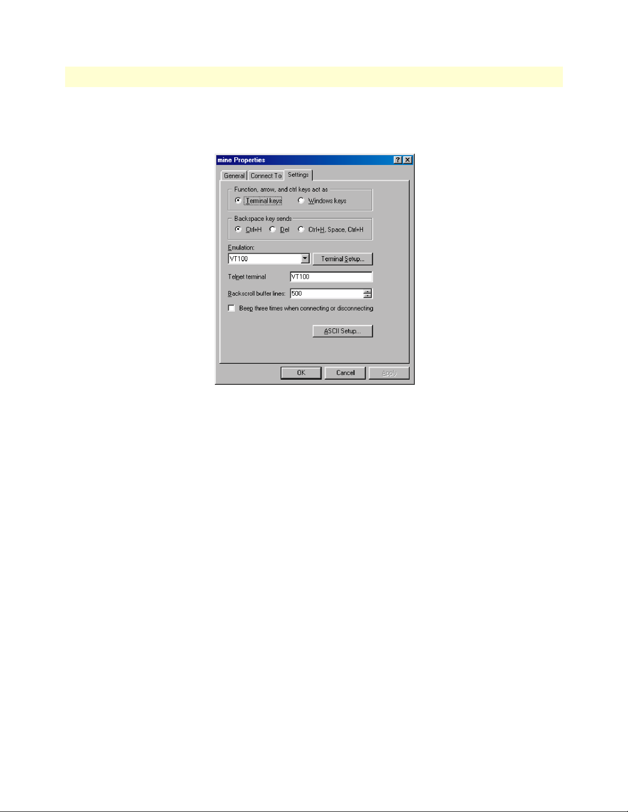
3 • Configuring the 3324 for operation Model 3324 User Guide
8. Configure the settings for Function, arrow and ctrl keys act as to Terminal keys as shown in figure 10, then
click
OK.
Figure 10. Terminal keys configuration
9. Connect the male end of the Model 3324 power cable to the power outlet.
10. When the PC connects with the Model 3324, boot up information will display on your HyperTerminal
connection window, followed by a login request window.
11. At the login window type the following login and password:
Login name: admin
Password: 123
The Main Menu displays (see figure 11 on page 33)
Note Operational keys are as follows:
Tab=Next Item; Backspace=Previous Item; Enter=Select ItemSelect
32 Initial configuration through the RS-232 control port
Page 33

Model 3324 User Guide 3 • Configuring the 3324 for operation
Figure 11. Main Menu
Set IP address
1. Do the following:
2. Choose Switch Static Configuration from the Main Menu screen (see figure 11).
Figure 12. Switch Configuration menu
3. Choose Administration Configuration (see figure 12). This takes you to the Device Configuration page (see
figure 13 on page 34).
Initial configuration through the RS-232 control port 33
Page 34

3 • Configuring the 3324 for operation Model 3324 User Guide
Figure 13. Device Configuration menu
4. Choose IP Configuration. This takes you to the IP Configuration page (see figure 13).
Figure 14. IP Configuration page
5. Choose Edit item to change ip address, subnet mask and gateway.
6. Use
7. Choose
8. Choose
9. Choose
34 Initial configuration through the RS-232 control port
CTRL+A to go back to actions.
Save item to save change and return to System Configuration page.
Previous Menu item to exit System Configuration page.
Main Menu item to exit the 3324 Switch Configuration page and return to Main Menu.
Page 35

Model 3324 User Guide 3 • Configuring the 3324 for operation
10. Choose Reboot System item.
11. Choose
Restart item to reboot your Model 3324.
Remote Network Management
Now that you have established an IP Address through the local serial console port (RS-232 port) you now have
the ability to remotely control and monitor your Patton Model 3324 through Telnet or SNMP (WWW). You
can also change your computer’s IP domain same with VDSL SWITCH. Then use the default IP address to
control this VDSL concentrator.
Controlling the Model 3324 remotely through TELNET
To enter Telnet, type the IP address of the Model 3324 to connect management system. And type user name
and password.
Default User Name: admin
Default Password: 123
Note For security reasons the Model 3324 will only allow either a Telnet
session or Console Port session at any given time. When ending a
Console Port session it is important to log out. If a user does not log
out you will not be able to log into the Model 3324 using Telnet.
SNMP Management does not have a user login limit.
Controlling the Model 3324 remotely through SNMP
The Patton Model 3324 provides a web browser to manage and monitor the performance of the Model 3324.
The default values are as follows:
• Default IP Address: 192.168.16.250
• Subnet Mask: 255.255.255.0
• Default Gateway: 192.168.16.1
• User Name: admin
• Password: 123
You can browse http://192.168.16.250, just type user name and password as above.
Figure 15. Web Management Home Overview
Remote Network Management 35
Page 36

3 • Configuring the 3324 for operation Model 3324 User Guide
Figure 16. Welcome page
Port Status
Through this page an administrator can see every ports status, user settings, and the negotiation results.
Figure 17. Port status page
State
Display Port status disable or enable. “UNLINK” is treated as “OFF”
Link Status
DOWN is “NO LINK”, UP is “LINK”
SNR (Signal to Noise Ratio)
The SNR is used to indicate the quality of the link. If the SNR value is greater than (>) 25, it means a good
link has been established between the 3324 and CPE.
36 Remote Network Management
Page 37
Model 3324 User Guide 3 • Configuring the 3324 for operation
Speed Status
• Config: Displays user configured port settings 1-24 at 5/10/15 Mbps and port 25/26 at 10/100/1000 Mbps
• Actual: Displays the actual line rate the individual links have achieved
Duplex Status
• Config: Displays user configured Full or Half-Duplex Mode
• Actual: Displays which mode is actually being achieved
Flow Control
Full-Displays the flow control status as enabled ON or disabled OFF
• Half: Displays the backpressure is in enabled ON or disabled OFF
• Actual: Displays what flow control is being used
Rate Control
• Ing: Displays the port effective ingress rate of user setting
• Egr: Displays the port effective egress rate of user setting.
Port Security
• Displays if a port is receiving Priority. If it is, it will read Enabled, if not, Disabled
• Port Security: Displays the user setting, it is either OFF or ON
Note To read a specific port’s information double-click on the port # you
wish to examine.
From this Port Status you can read the following:
• Port: This is the port # you have double-clicked
• State:
• Link:
Remote Network Management 37
Page 38

3 • Configuring the 3324 for operation Model 3324 User Guide
• TxGoodPkt:
• TxBadPkt:
• RxGoodPkt:
• RxBadPkt:
• TxAbort:
• Collision:
• DropPkt:
Port Statistics
This page provides and administrator a quick overview on every ports LAN statistics. These statistics can be
rest at any time by double clicking the reset icon at the bottom of the menu screen.
Administrator
Most of the management functions of the 3324 can be found in this menu. Management functions include:
• IP address
• Switch settings
• Console port information
• Port controls
• Trunking
• Filter database
• VLAN configuration
• Spanning tree
38 Administrator
Page 39

Model 3324 User Guide 3 • Configuring the 3324 for operation
• Port Sniffer
• SNMP
• Security Manager
• 802.1x configuration
IP Address Configuration
The administrator can configure the IP Address from this screen. Once the change has been made, click the
Apply icon at the bottom of the menu screen. Once the IP Address has been modified by the administrator the
box must be reset to for the new IP Address to be implemented.
Basic Switch Settings
Description
Display the name of the device
MAC Address
The unique hardware address assigned by the manufacturer (default)
Firmware Version
Displays the 3324’s hardware revision
Default Config Value Version
Displays write to default EEPROM value table version
Advanced Switch Settings
Mac Address Age-out Time
Enter the number of second that in inactive MAC address remains in the 3324’s address table. The valid range
is between 300–765 seconds. (Default 300 seconds).
Administrator 39
Page 40

3 • Configuring the 3324 for operation Model 3324 User Guide
Max Bridge Transit Delay Bound Control
Limits the packets queuing time in the concentrator. When enabled the packets queued past the time limit will
be dropped. The valid time limits are 1 second, 2 seconds, 4 seconds, and off. (Default is 1 second)
Broadcast Storm Filter
To configure Broadcast Storm Control, enable it and set the upper threshold for the individual ports. The
threshold is the percentage of the port’s total bandwidth used by broadcast traffic. When broadcast traffic for a
port rises about the threshold, the broadcast storm control will become active. The valid range is 5%, 10%,
15%, 20%, 25%, and OFF.
Priority Queue Service Settings
First Come First Service
The sequence of packets sent is dependent on the order the packets arrived.
All High Before Low
The high priority packets are sent before the low priority packets.
WRR (Weighted Round-Robin)
Select the preference given to packets in the 3324’s high-priority queue. These options represent the number
of high priority packets that will be sent before one low priority packet is sent. For example, 5 High/2 Low
means that the 3324 will send the 5 high priority packets before sending the 2 low priority packets.
40 Administrator
Page 41

Model 3324 User Guide 3 • Configuring the 3324 for operation
Enable Delay Bound
Limits the low priority packets queuing time in switch. The Default Max Delay Time is 255ms. If the low priority packets stay in 3324 exceeds Max Delay Time, it will be sent. The valid range is 1~255 ms.
Note Make sure that the “Max Bridge Transit Delay Bound Control” is
enabled before the Delay Bound is enabled because enable Delay
Bound must work under “Max Bridge Transit Delay Bound Control”
is enabled situation.
QoS Policy High Priority Levels
0–7 priority level can map to high or low queue.
Protocol Enable Settings
This menu allows you to enable Spanning Tree Protocol and IGMP.
Enable STP
Default recommend to enable Spanning Tree Protocol
Enable IGMP
Enable Internet Group Multicast Protocol
Console Port Settings
The console uses a standard UART interface that communicates with serial port. The administrator can use
the windows program, HyperTerminal, to access the Model 3324.
• Bits per seconds: 9600
• Data Bits: 8
• Parity: none
Administrator 41
Page 42

3 • Configuring the 3324 for operation Model 3324 User Guide
• Stop Bits: 1
• Flow Control: none
Port Control Settings
This section shows you how to change the various ports of the Model 3324.
State
The administrator can disable or enable any port.
• Enable (ON)
• Disable (OFF)
Negotiation
The administrator can set the auto negotiation mode for the CPE devices through the 3324. The three choices
are:
• Auto
• Nway (TM) (specify the speed/duplex on this port and enable auto-negotiation)
• Force of Per Port
Speed
User can set 5Mbps/10Mbps/15Mbps/LWD for ports 1~24. For ports 25 and 26 the options available are
10/100/1000Mbps.
10/100Mbps speed on Port25~Port26 (based on copper uplink). If a GBIC 1000Base-FX is used then then
the uplink port will be forced to1000Mbps.
The following distance are achievable between the 3324 and VDSL CPE when using standard 24 Gauge
(0.5mm) cable:
• 5 Mbps -> 4,920 feet (1.5km)
• 10 Mbps -> 3,940 feet (1.2km)
• 15 Mbps -> 3,280 feet (1.0km)
• Link Watch Dog (LWD) -> 6,070 feet (1.8~1.9km)
Link Watch Dog(LWD) function: The LWD enables the 3324 to reconnect to the CPE modem with known
and predefined VDSL link values. This is necessary whenever loading normal VDSL link parameters fails.
Procedure for Changing VDSL Ports Speed Settings:
1. Confirm the VDSL port currently has a link before you change the speed.
2. Select the port you want to configure. (Ports 1-24 are the VDSL ports)
3. Select the line rate (speed) you would like the port to run at
4. Click “Apply” to confirm the settings
42 Administrator
Page 43

Model 3324 User Guide 3 • Configuring the 3324 for operation
Note The VDSL port will link down. After 20 seconds, the VDSL port will
link up again with the line rate (speed) you have configured.
Rate Control
Port 1-24 on the Model 3324 supports port-by-port ingress and egress rate control. For example, assume Port
1 is 10Mbps, users can set it’s effective egress rate is 1Mbps, ingress rate is 500 kbps. The Model 3324 will be
performing flow control or back-pressure to confine the ingress rate to meet the specified rate.
• Ingress: Type the port effective ingress rate. The valid range is 0–100. (Default is 100K) Entering 0 disables
rate control. (100 = 10 Mbps)
• Egress: Type the port effective egress rate. The valid range is 0–100. (Default is 100K) Entering 0 disables
rate control. (100 = 10 Mbps)
Port Security
When a port is in security mode the port will be “locked” without the permission of address learning. Only the
incoming packets with MAC addresses already existing in the address table can be forwarded normally. Users
can disable the port from learning any new MAC addresses, and then use the static MAC addresses screen to
define a list of MAC addresses that can be use on the secure port. Enter the settings, then click the Apply button to make the changes to the Model 3324.
Figure 18. VDSL Port Controls
Figure 19. Ethernet Port Controls
Duplex
User can set full-duplex or half-duplex mode of per port.
Administrator 43
Page 44

3 • Configuring the 3324 for operation Model 3324 User Guide
Flow Control
• Full: User can set flow control function is enable or disable in full mode.
• Half: User can set backpressure is enable or disable in half mode.
Trunking
The link aggregation control protocol (LACP) provides a standardized means for exchanging information
between Partner Systems on a link. Link aggregation lets you group up to eight consecutive ports into a single
dedicated connection. This feature can expand bandwidth to a device on the network. LACP operation
requires full-duplex mode, more detail information refers to IEEE802.3ad.
System Priority
This is the value used to identify the active LACP. The 3324/Switch with the lowest value has the highest priority and is selected as the active LACP. There are six steps to activate LACP.
1. Group ID: There are seven trunk groups to provided configure. Choose the "group id" and click "Get".
2. LACP: If enabled, the group is LACP static trunking group. If disabled, the group is local static trunking
group All ports support LACP dynamic trunking group. If connecting to the device that also supports
LACP, the LACP dynamic trunking group will be created automatically.
3. Work Ports: Allows a maximum of four ports to be aggregated at the same time. If the LACP static
trunking group exceeds the 4 port maximum it will set to standby, and will aggregate if the work ports
fail. If local static trunking group is set, the number must be as same as the group member ports.
4. Select the ports to join the trunking group. A maximum of four ports can be aggregated at the same time.
5. If LACP is enabled, you can configure LACP Active/Passive status for each port on State Activity page.
6. Click Apply.
44 Administrator
Page 45

Model 3324 User Guide 3 • Configuring the 3324 for operation
When you are setting the LACP aggregator, you will see one of the following screens below.
This page is when no group is active. LACP is not working.
This page shows a Static Trunking group. LACP is working.
Administrator 45
Page 46

3 • Configuring the 3324 for operation Model 3324 User Guide
State Activity
• Active (select): The port automatically sends LACP protocol packets.
• Passive (no select): The port does not automatically sends LACP protocol packets, and responds only if it
receives LACP protocol packets from the opposite device.
A link having either two active LACP ports or one active port can perform dynamic LACP trunking. If a link
has two passive LACP ports, dynamic LACP trunking will not be performed because both ports are waiting for
and LACP protocol packet from the opposite device. If you are active LACP’s actor, when you are select
trunking port, the active status will be created automatically.
Filter Database
IGMP Snooping
The Model 3324 supports IP multicast. IP manages multicast traffic by using switches, routers, and hosts that
support IGMP (Internet Group Management Protocol). Enabling IGMP allows the ports to detect IGMP
queries and report packets and manage IP multicast traffic through the switch. IGMP can be enabled through
the web management’s switch settings advanced page. From the Switch Settings Advanced page, choose IGMP
snooping. This page will allow you to view the different multicast groups ,VID and member ports. IP multicast addresses range from 224.0.0.0 through 239.255.255.255.
46 Administrator
Page 47

Model 3324 User Guide 3 • Configuring the 3324 for operation
IP manages multicast traffic by using switches, routers, and hosts that support IGMP. Enabling IGMP allows
the ports to detect IGMP queries and report packets and manage IP multicast traffic through the switch.
IGMP have three fundamental types of message as follows:
Message Description
Query A message sent from the querier (IGMP router or switch) asking for a response
from each host belonging to the multicast group.
Report A message sent by a host to the querier to indicate that the host wants to be or is a
member of a given group indicated in the report message.
Leave Group A message sent by a host to the querier to indicate that the host has quit to be a m
ember of a specific multicast group.
Static MAC Address
When you add a static MAC address, it will remain in the switch's address table, regardless of whether the
device is physically connected to the switch or not. This saves the switch from having to re-learn a device's
MAC address in cases where a device may have been powered off or disconnected from the network.
1. From the main menu, click administrator _ Filter Database _ Static MAC Address.
Administrator 47
Page 48

3 • Configuring the 3324 for operation Model 3324 User Guide
2. In the MAC address box, enter the MAC address to and from which the port should permanently for-
ward traffic, regardless of the device’s network activity.
3. In the Port Number box, enter a port number.
4. If tag-based (IEEE 802.1Q) VLANS are set up on the switch, static addresses are associated with individ-
ual VLANS. Type the VID (tag-based VLANS) to associate with the MAC address.
5. Click the
Add button.
MAC Filtering
MAC address filtering allows the switch to drop unwanted traffic. Traffic is filtered based on the destination
addresses.
1. In the MAC Address box, enter the MAC address that wants to filter.
2. If tag-based (802.1Q) VLAN are set up on the switch, in the VLAN ID box, type the VID to associate
with the MAC address.
3. Click the
4. Choose the MAC address that you want to delete and then click the
Add button.
Delete button.
VLAN Configurations
The Model 3324 supports both port-based and 802.1Q (tagged-based) VLAN, through the web management
page.
48 Administrator
Page 49

Model 3324 User Guide 3 • Configuring the 3324 for operation
A Virtual LAN (VLAN) is a logical network grouping that limits the broadcast domain. It allows you to isolate
network traffic so only members of the VLAN receive traffic from the same VLAN members. Basically, creating
a VLAN is logically equivalent to reconnecting a group of network devices to another Layer 2 switch, even
though the network devices have the same physical connection.
The default configuration for VLAN support is disable.
Note If you change the VLAN Operation Modem from disabled to
enabled, you must wait 50 seconds. Every time you reboot the Patton Model 3324 you will have to change the VLAN mode to a valid
value.
Support Port-based VLAN
Packets can only be transmitted and received among members of the same VLAN group. All unselected ports
are treated as though they belong to another single VLAN. If the port-based VLAN is enabled, the VLAN-tagging is ignored.
Figure 20. Support Tag-based VLAN (IEEE 802.1Q VLAN)
1. Click Add to create a new VLAN group.
2. Enter the VLAN name, group ID and select the members for the new VLAN.
3. Click
Apply.
4. If there are many groups that over the limit of one page, you can click the “Next Page” to view other
VLAN groups.
Administrator 49
Page 50

3 • Configuring the 3324 for operation Model 3324 User Guide
Note If the trunk group exists, you can see it (ex. TRK1,TRK2…..) in
select menu of ports, and you can configure it is the member of the
VLAN or not.
Tagged-based VLAN
Tagged-based VLAN is an IEEE 802.1Q specification standard. Because this is a standard, it is possible to create a VLAN across devices from various switch venders. IEEE 802.1Q VLAN uses a technique to insert a “tag”
into the Ethernet frames. This “tag” contains a VLAN Identifier (VID) that indicates the VLAN numbers.
In order to for a station to send packets to different VLANs, it itself has to be either capable of tagging packets
it sends with VLAN tags, or it must be attached to a VLAN-aware bridge that is capable of classifying and tagging the packets with different VLAN ID based on not only default PVID but also other information about
the packet, such as the protocol.
Figure 21. Support Tag-based VLAN (IEEE 802.1Q VLAN)
From the VLAN Configuration page, the administrator can create a Tag-based VLAN, and enable or disable
GVRP (Generic Attribute Registrations Protocol). You can configure up to 256 VLAN groups. Once 802.1Q
50 Administrator
Page 51

Model 3324 User Guide 3 • Configuring the 3324 for operation
VLAN is enabled, all ports on the Model 3324 will belong to the default VLAN (VID 1). The default VLAN
cannot be deleted.
GVRP allows automatic VLAN configuration between the switch and nodes. If the Model 3324 is connected
to a device with GVRP enabled, you can send a GVRP request using the VID of a VLAN defined on the Patton Model 3324, the Model 3324 will then automatically add that device to the existing VLAN.
To create a VLAN and add tagged member ports to it follow the steps below.
From the main menu:
1. Click administrator
2. Click VLAN configuration
Administrator 51
Page 52

3 • Configuring the 3324 for operation Model 3324 User Guide
3. Click Add then you will see the page below.
4. Type a name for the new VLAN.
5. Type a VID (between 2-4,094). The default is 1.
6. Choose the protocol type.
7. From the available ports box on the left, select which ports to add to the 3324 and click “Add ”. If the
trunk groups exist, you can see it in here (ex:TRK1,TRK2…). If you want to configure the TRK as a
member of the VLAN you can do it through this screen.
8. Click Next. This will take you to figure 24.
Figure 22. VLAN Tag Menu
52 Administrator
Page 53

Model 3324 User Guide 3 • Configuring the 3324 for operation
9. Using this page to set the outgoing frames are VLAN-Tagged frames or no. Then click Apply.
– Tag: outgoing frames with VLAN-Tagged.
– Un-tag: outgoing frames without VLAN-Tagged.
Port VID
Do the following to configure port VID settings:
From the main Tag-based (IEEE 802.1Q) VLAN page, click Port VID Settings.
1. Click administrator
2. Click VLAN configuration
3. Click Port VID and that will take you to the page below (figure 23)
Figure 23. Port VID menu screen
4. Set the port VLAN ID that will be assigned to untagged traffic on a given port. This feature is useful for
accommodating devices that you want to participate in the VLAN but that don’t support tagging. Each
port of the Model 3324 allows the user to set one PVID, the range is 1~255 and the default PVID is 1.
The PVID must as same as the VLAN ID that the port belong to VLAN group, or the untagged traffic will
be dropped.
Ingress Filtering
Ingress filtering allows frames belonging to a specific VLAN to be forwarded if the port belongs to that VLAN.
The Model 3324 has two ingress filtering rules:
• Ingress Filtering Rule 1: Forward only packets with VID matching this port's configured VID.
• Ingress Filtering Rule 2: Drop Untagged Frame.
Spanning Tree Protocol Settings
Spanning-Tree Protocol (STP) is a standardized method (IEEE 802.1D ) for avoiding loops in switched networks. When STP is enabled, it ensures that only one path at a time is active between any two nodes on the
network. You can enable Spanning-Tree Protocol through the web management’s Switch Setting Advanced
Administrator 53
Page 54

3 • Configuring the 3324 for operation Model 3324 User Guide
menu, then select enable STP. It is recommended that you enable STP on your Model 3324 to ensure a single
active path on your network. Additionally, you can view STP information about the Root Bridge by clicking
on Root Bridge Information (see figure 24).
Figure 24. Root Bridge Information
You can also view STP port status by clicking on STP Port Status
Figure 25. STP Port Status
You can set new values for the STP parameter in the Configuring Spanning Tree Parameters screen. Once the
new values are set be sure to click the Apply button to save the configuration. The parameters that can be
modified are as follows:
• Priority: This value is used to identify the root bridge. The bridge with the lowest value has the highest pri-
ority and will be selected as the root bridge. The valid range is between 1-65,535.
• Max Age: This value represents the number of seconds a bridge waits without receiving STP configuration
messages before attempting a reconfiguration. The valid range is between 6-10.
• Hello Time: Hello Time represents the number of seconds between the transmission of STP configuration
messages. The valid range is a between 1-10.
54 Administrator
Page 55

Model 3324 User Guide 3 • Configuring the 3324 for operation
• Forward Delay Time: Forward Delay Time is the number of seconds a port waits before changing from its
STP learning and listening states to the forwarding state. The valid range is from 4-30.
Port Priority and Path Cost can be configured on each port. When finished click the apply icon.
• Port Priority: Using Port Priority will make that port more or less likely to become the root port, the rage is
0-255,default setting is 128 the lowest number has the highest priority.
• Path Cost: Specifies the path Cost of the port that switch uses to determine which port are the forwarding
ports the lowest number is forwarding ports, the rage is 1-65535 and default value base on IEEE802.1D
10Mb/s = 50-600 100Mb/s = 10-60 1000Mb/s = 3-10
Port Sniffer
Port Sniffer is a method for monitoring traffic in switched networks. Traffic that goes in or out of the monitored ports will be duplicated into the sniffer port.
• Sniffer Mode: Press Space key to set sniffer mode: Disable\Rx\Tx\Both.
• Monitoring Port: The sniffer port can be used to see all monitored port traffic. You can connect the sniffer
port to LAN analyzer or net x-ray.
• Monitored Port: These are the ports you want to monitor. All monitored port traffic will be copied to the
sniffer port. You can select up to a maximum of 25 ports to monitor ports.
If you want to disable the function, you must select monitor port to none.
Administrator 55
Page 56

3 • Configuring the 3324 for operation Model 3324 User Guide
SNMP Settings
Any Network Management running the simple Network Management Protocol (SNMP) can manage the
Model 3324, provided the Management Information Base (MIB) is installed correctly on the management station. SNMP is a protocol that governs the transfer of information between management and agent.
Use this page to define management stations, trap managers, and to enter SNMP community strings. Users
can also define a name, location, and contact person for the 3324. Fill in the system options data, then click
Apply to update the changes on this page.
• Name: Enter a name to be used for the switch.
• Location: Enter the location of the switch.
• Contact: Enter the name of a person or organization.
Community Strings serve as passwords and can be entered as one of the following:
• RO (Read Only): Enables requests accompanied by this string to display MIB-object information.
• RW (Read Write): Enables requests accompanied by this string to display MIB-object information and to
set MIB objects.
56 Administrator
Page 57

Model 3324 User Guide 3 • Configuring the 3324 for operation
Trap Manager is a management station that receives traps (system alerts generated by the 3324). If no trap
manager is defined, no traps are issued. Create a trap manager by entering the IP address of the station and a
community string.
Security Manager
Using this page, an administrator can change the web management’s user name and password.
1. User name: Type the new user name.
2. Password: Type the new password.
3. Reconfirm password: Retype the new password.
4. Click Apply
System Configuration (802.1X)
802.1x uses the physical access characteristics of an IEEE802 LAN infrastructures to provide a means of
authenticating and authorizing devices attached to a LAN port through a point-to-point connection. 802.1X
will>>>>>>>>>>>>>>>>>> characteristics, and of preventing access to that port in cases in which the authentication and authorization process fails.
To enable 802.1x, you will need to fill in the following authentication server information :
• Radius Server IP Address: the IP address of the authentication server.
• Server Port: The UDP port number used by the authentication server to authenticate.
Administrator 57
Page 58

3 • Configuring the 3324 for operation Model 3324 User Guide
• Accounting Port: The UDP port number used by the authentication server to retrieve accounting informa-
tion.
• Shared Key: A key shared between this switch and authentication server.
• NAS Identifier: A string used to identify this switch.
Per port Configuration
In this page, you can select the specific port and configure the authorization state. Each port can select four
kinds of authorization state:
• Fu: force the specific port to be unauthorized.
• Fa: force the specific port to be authorized.
• Au: the state of the specific port was determinied by the outcome of the authentication.
• No: the specific port didn't support 802.1x function.
Misc. Configuration
In this page, you can change the default configuration for the 802.1x standard:
• Quiet Period: Defines periods of time during which it will not attempt to acquire a supplicant (Default
time is 60 seconds).
• Tx Period: Determines when an EAPOL PDU is to be transmitted (Default value is 30 seconds).
• Supplicant Timeout: Determines timeout conditions of the exchanges between the supplicant and authen-
tication server (Default value is 30 seconds).
• Server Timeout: Determines timeout conditions of the exchanges between the authenticator and authenti-
cation server (Default value is 30 seconds).
• ReAuthMax: Determines the number of reauthentication attempts that are permitted before the specific
port becomes unauthorized (Default value is 2 times).
• ReAuth Period: Determines a nonzero number of seconds between periodic re-authentication of the suppli-
cations (Default value is 3600 seconds).
TFTP Update Firmware
The following menu options provide some system control functions to allow a user to update firmware and
remote boot switch system:
• Install TFTP Turbo98 and execution.
• Copy firmware update version image.bin to TFTP Turbo98 directory.
• In web management select administrator—TFTP update firmware.
58 Administrator
Page 59

Model 3324 User Guide 3 • Configuring the 3324 for operation
• Download new image.bin file then in web management press <update firmware>.
• After update finished, press <reboot> to restart switch.
Using TFTP
TFTP Restore Configuration
Use this page to set the TFTP server address. You can restore the EEPROM values from here. It is important
to first put the image back in the TFTP server, then the Model 3324 will download the original flash image.
Administrator 59
Page 60

3 • Configuring the 3324 for operation Model 3324 User Guide
TFTP Backup Configuration
Use this page to set the TFTP servers IP address. You can save the current EEPROM value here. Once the
EEPROM value has been saved, go to the TFTP restore configuration page to restore the EEPROM value.
Resetting the Model 3324
Reset the Patton Model 3324 to default configuration, default value as below.
Rebooting the Model 3324
Reboot the Patton Model 3324 in software reset.
60 Administrator
Page 61

Chapter 4 Applications
Chapter contents
MxU multi-service delivery....................................................................................................................................62
High bandwidth backbone ....................................................................................................................................63
61
Page 62

4 • Applications Model 3324 VDSL Carrier-Class Aggregator Configuration Guide
MxU multi-service delivery
The Model 3324 provides a high speed, 5/10/15Mbps transmission over existing home telephone wiring over
a single Internet account to provide simultaneous independent Internet access to multiple users. Either ISDN
or POTS Telephone systems can be used. VDSL Technology allows the simultaneous use of a telephone system
(voice) and VDSL network (data) over one voice-grade twisted pair wire.
Figure 26. MxU Multi-Service Delivery
62 MxU multi-service delivery
Page 63

Model 3324 VDSL Carrier-Class Aggregator Configuration Guide 4 • Applications
High bandwidth backbone
The Model 3324 provides 10/100/1000Mbps auto sensing Uplinks for bandwidth intensive applications.
Figure 27. Application for VOD and Video conference
High bandwidth backbone 63
Page 64

4 • Applications Model 3324 VDSL Carrier-Class Aggregator Configuration Guide
1068DV
CPE
3324
Figure 28. Broadband access applications utilizing Model 3324
64 High bandwidth backbone
Page 65

Chapter 5 Troubleshooting
Chapter contents
Diagnosing VDSL indicators.................................................................................................................................66
System Diagnostics................................................................................................................................................66
Power and Cooling Problems ..........................................................................................................................66
Installation ............................................................................................................................................................67
Transmission Mode ........................................................................................................................................67
Cabling ...........................................................................................................................................................67
Physical Configuration ....................................................................................................................................67
System Integrity ..............................................................................................................................................67
CPE (Customer Premise/Remote) Side Starts Link Watch Dog ............................................................................67
65
Page 66

5 • Troubleshooting Model 3324 VDSL Carrier-Class Aggregator Configuration Guide
Diagnosing VDSL indicators
The Model 3324 is easily monitored through its comprehensive panel indicators. These indicators assist the
network manager in identifying problems the Model 3324 may encounter. This section describes the common
problems you may encounter and possible solutions.
Symptom Cause Solution
POWER indicator does not light
up (green) after power on.
Link indicator does not light up
(green) after making a connection
Defective power outlet, power
cord, internal power supply
Network interface (e.q., a network adapter card on the
attached device), network
cable, or switch port is defective
Check the power outlet by trying another
outlet that is functioning properly. Check
the power cord with another device. If
these measures fail to resolve the problem, have the unit power supply
replaced by a qualified distributor.
1. Verify the switch and attached device
are powered on.
2. Be sure the cable is plug into both
the switch and corresponding
device.
3. Verify that the proper cable type is
used and its length does not exceed
specified limits.
4. Check the adapter on the attached
device and cable connections for
possible defects.
5. Replace the defective adapter or
cable if necessary.
I had a VDSL link. But, after dis-
connecting the line for several
minute, there is no link any
more.
This is normal behavior for the modem.
The LWD (Link Watch Dog) is automatically activated in the VDSL modem,
when ever is no link after a specified
time. Users just re-plug the power of
VDSL modem, and then they can link
again and solve this problem.
System Diagnostics
Power and Cooling Problems
If the POWER indicator does not turn on when the power cord is plugged in, you may have a problem with
the power outlet, power cord, or internal power supply as explained in the previous section. However, if the
unit should turn itself off after running for a while, check for loose power connections, power losses or surges
at the power outlet, and verify that the fan on back of the unit is unobstructed and running prior to shutdown.
If you still cannot isolate the problem, then the internal power supply may be defective. In this case, contact
your supplier for assistance.
66 Diagnosing VDSL indicators
Page 67

Model 3324 VDSL Carrier-Class Aggregator Configuration Guide 5 • Troubleshooting
Installation
Verify that all system components have been properly installed. If one or more components appear to be malfunctioning (e.g., the power cord or network cabling), test them in an alternate environment, where you are
sure that all the other components are functioning properly.
Transmission Mode
The default transmission mode of the RJ-45 ports is auto-negotiation. Therefore, if the Link signal is disrupted
(e.g., by unplugging the network cable and plugging it back in again, or by resetting the power), the port will
try to reestablish communications with the attached device Model 3324 through auto-negotiation. If autonegotiation fails, then communications are set to half duplex by default. Based on this type of industry-standard connection policy, if you are using a full-duplex device that does not support auto-negotiation, communications can easily be lost (i.e., reset to the wrong mode) whenever the attached device is reset or experiences a
power fluctuations. The best way to resolve this problem is to upgrade these devices to products that will support auto-negotiation.
Cabling
• Verify that the cable type is correct.
• Be sure RJ-45 cable connectors are securely fastened into the correct ports.
• Use 100W straight-through cables for all standard connections.
• Use Category 5 cable for 100/1000Mbps Fast Ethernet connections, or Category 3, 4 or 5 cables for stan-
dard 10Mbps Ethernet connections.
• Be sure RJ21 phone wiring, use 18~26 gauge.
• Make sure all devices are connected to the network. Equipment any have been unintentionally discon-
nected from the network.
• When cascading two devices using RJ-45 station ports at both ends of the cable (Model 3324 supports auto
MDIX), without crossover cable can be used.
Physical Configuration
If problems occur after altering the network configuration, restore the original connections, and try to track the
problem down by implementing the new changes, one step at a time. Ensure that cable distances and other
physical aspects of the installation do not exceed recommendations
System Integrity
As a last resort verify the switch integrity with a power-on reset. Turn the power to the switch off and then on
several times. If the problem still persists and you have completed all the preceding diagnoses, contact your
dealer for assistance.
CPE (Customer Premise/Remote) Side Starts Link Watch Dog
If the CPE side (VDSL Modem) is on power standby for an excess of 20 minutes without connecting to the
Model 3324, the link has failed. The users must power cycle the CPE once to clear and the CPE should reconnect to the Model 3324.
Installation 67
Page 68

5 • Troubleshooting Model 3324 VDSL Carrier-Class Aggregator Configuration Guide
68 CPE (Customer Premise/Remote) Side Starts Link Watch Dog
Page 69

Chapter 6 Contacting Patton for assistance
Chapter contents
Introduction..........................................................................................................................................................70
Contact information..............................................................................................................................................70
Warranty Service and Returned Merchandise Authorizations (RMAs)...................................................................70
Warranty coverage ..........................................................................................................................................70
Out-of-warranty service .............................................................................................................................70
Returns for credit ......................................................................................................................................70
Return for credit policy .............................................................................................................................71
RMA numbers ................................................................................................................................................71
Shipping instructions ................................................................................................................................71
69
Page 70

6 • Contacting Patton for assistance Model 3324 VDSL Carrier-Class Aggregator Configuration Guide
Introduction
This chapter contains the following information:
• “Contact information”—describes how to contact PATTON technical support for assistance.
• “Warranty Service and Returned Merchandise Authorizations (RMAs)”—contains information about the
RAS warranty and obtaining a return merchandise authorization (RMA).
Contact information
Patton Electronics offers a wide array of free technical services. If you have questions about any of our other
products we recommend you begin your search for answers by using our technical knowledge base. Here, we
have gathered together many of the more commonly asked questions and compiled them into a searchable
database to help you quickly solve your problems.
• Online support—available at www.patton.com.
• E-mail support—e-mail sent to support@patton.com will be answered within 1 business day
• Telephone support—standard telephone support is available 5 days a week, from 8:00am to 5:00pm EST
by calling +1 (301) 975-1007
Warranty Service and Returned Merchandise Authorizations (RMAs)
Patton Electronics is an ISO-9001 certified manufacturer and our products are carefully tested before shipment. All of our products are backed by a comprehensive warranty program.
Note If you purchased your equipment from a Patton Electronics reseller,
ask your reseller how you should proceed with warranty service. It is
often more convenient for you to work with your local reseller to
obtain a replacement. Patton services our products no matter how
you acquired them.
Warranty coverage
Our products are under warranty to be free from defects, and we will, at our option, repair or replace the product should it fail within one year from the first date of shipment. Our warranty is limited to defects in workmanship or materials, and does not cover customer damage, lightning or power surge damage, abuse, or
unauthorized modification.
Out-of-warranty service
Patton services what we sell, no matter how you acquired it, including malfunctioning products that are no
longer under warranty. Our products have a flat fee for repairs. Units damaged by lightning or other catastrophes may require replacement.
Returns for credit
Customer satisfaction is important to us, therefore any product may be returned with authorization within 30
days from the shipment date for a full credit of the purchase price. If you have ordered the wrong equipment or
you are dissatisfied in any way, please contact us to request an RMA number to accept your return. Patton is
not responsible for equipment returned without a Return Authorization.
70 Introduction
Page 71

Model 3324 VDSL Carrier-Class Aggregator Configuration Guide 6 • Contacting Patton for assistance
Return for credit policy
• Less than 30 days: No Charge. Your credit will be issued upon receipt and inspection of the equipment.
• 30 to 60 days: We will add a 20% restocking charge (crediting your account with 80% of the purchase
price).
• Over 60 days: Products will be accepted for repairs only.
RMA numbers
RMA numbers are required for all product returns. You can obtain an RMA by doing one of the following:
• Completing a request on the RMA Request page in the Support section at www.patton.com
• By calling +1 (301) 975-1000 and speaking to a Technical Support Engineer
• By sending an e-mail to returns@patton.com
All returned units must have the RMA number clearly visible on the outside of the shipping container. Please
use the original packing material that the device came in or pack the unit securely to avoid damage during
shipping.
Shipping instructions
The RMA number should be clearly visible on the address label. Our shipping address is as follows:
Patton Electronics Company
RMA#: xxxx
7622 Rickenbacker Dr.
Gaithersburg, MD 20879-4773 USA
Patton will ship the equipment back to you in the same manner you ship it to us. Patton will pay the return
shipping costs.
Warranty Service and Returned Merchandise Authorizations (RMAs) 71
Page 72

6 • Contacting Patton for assistance Model 3324 VDSL Carrier-Class Aggregator Configuration Guide
72 Warranty Service and Returned Merchandise Authorizations (RMAs)
Page 73

Appendix A Specifications
Chapter contents
VDSL line interface...............................................................................................................................................74
POTS-ISDN interface...........................................................................................................................................74
Modulation ...........................................................................................................................................................74
Frequency range ....................................................................................................................................................74
Transmission .........................................................................................................................................................74
Management .........................................................................................................................................................74
Ethernet standards.................................................................................................................................................74
Management standards..........................................................................................................................................74
LED indicators......................................................................................................................................................74
Power supply .........................................................................................................................................................74
Compliance ...........................................................................................................................................................74
Environment .........................................................................................................................................................74
Operating temperature ....................................................................................................................................74
Humidity ........................................................................................................................................................75
Dimensions ...........................................................................................................................................................75
Weight ..................................................................................................................................................................75
73
Page 74

A • Specifications Model 3324 VDSL Carrier-Class Aggregator Configuration Guide
74
Page 75

Model 3324 VDSL Carrier-Class Aggregator Configuration Guide A • Specifications
VDSL line interface
24 ports presented on one RJ-21
POTS-ISDN interface
24 ports presented on one RJ-21
Modulation
QAM (Quadrature Amplitude Modulation)
Frequency range
• VDSL: 1–8 MHz
• POTS/ISDN: 0–120 kHz
Transmission
Software 5/10/15 Mbps symmetrical line rates
Management
In-Band/out-of-band (DB9 RS-232 Console, Telnet, or HTTP)
Ethernet standards
802.1d (Spanning Tree), 802.1p (Priority Queuing), 802.1Q (VLAN Tagging), 802.3ad (Port Trunking),
802.3x (Flow Control),802.3 (Ethernet), 802.3u (Fast Ethernet), 802.3z (Gigabit Ethernet)
Management standards
SNMP RFC-1493 Bridge MIBs, RFC-1213 MIB II, RFC-1643 Ethernet MIB & Enterprise MIB, RFC-1757
RMON MIB (RMON groups 1,2,3,9)
LED indicators
Power, Error, VDSL status, and Ethernet Uplink Status
Power supply
Internal AC: 120–240 VAC (50–60 Hz)
Compliance
EMC Directive 89/336/EEC, Low Voltage Directive 73/23/EEC; CE Mark
Environment
Operating temperature
41 to 122°F (5 to 50°C)
VDSL line interface 75
Page 76

A • Specifications Model 3324 VDSL Carrier-Class Aggregator Configuration Guide
Humidity
10–90% non-condensing
Dimensions
2.0H x 17.5W x 16.5L inch (5.08H x 44.45W x 41.91L cm)
Weight
12.5 lbs (5.66 kg)
76 Dimensions
Page 77

Appendix B Cabling
Chapter contents
Introduction..........................................................................................................................................................78
77
Page 78

B • Cabling Model 3324 VDSL Carrier-Class Aggregator Configuration Guide
Introduction
RJ-21 Telco ports distribution
Table 3. RJ-21 Pin and VDSL port contrast list
VDSL 50 Pin RJ-21 Cable Connector List
Cable Characteristic = 24 AWG twist wire
VDSL Port No. RJ-21 Cable No.
1 24 & 49
2 23 & 48
3 22 & 47
4 21 & 46
5 20 & 45
6 19 & 44
7 18 & 43
8 17 & 42
9 16 & 41
10 15 & 40
11 14 & 39
12 13 & 38
13 12 & 37
14 11 & 36
15 10 & 35
16 9 & 34
17 8 & 33
18 7 & 32
19 6 & 31
20 5 & 30
21 4 & 29
22 3 & 28
23 2 & 27
24 1 & 26
Note RJ-21 Pins 25 and 50 are not used
78 Introduction
Page 79

Model 3324 VDSL Carrier-Class Aggregator Configuration Guide B • Cabling
Figure 29. RJ-21 Cable Drawing (1500 cm Male to Male)
Introduction 79
Page 80

B • Cabling Model 3324 VDSL Carrier-Class Aggregator Configuration Guide
80 Introduction
Page 81

Appendix C VDSL Spectrum
Chapter contents
Introduction..........................................................................................................................................................82
81
Page 82

C • VDSL Spectrum Model 3324 VDSL Carrier-Class Aggregator Configuration Guide
Introduction
Spectrum allocation
VDSL Technology – Requirements & Definitions
Spectral Allocation
• Co-exists with legacy Voice and ISDN services
• Co-exists with other xDSL technologies
• Programmable notch filter to avoid Radio Frequency Interference
82 Introduction
Page 83

Appendix D Example of VLAN Setting
Chapter contents
Introduction..........................................................................................................................................................84
83
Page 84

D • Example of VLAN Setting Model 3324 VDSL Carrier-Class Aggregator Configuration Guide
Introduction
Web management -> Administrator -> Switch settings -> Advanced: protocol setting -> VLAN Operation
Mode: Select “Port_Based”
Web management -> Administrator -> Switch settings -> Vlan Configuration:
84 Introduction
Page 85

Model 3324 VDSL Carrier-Class Aggregator Configuration Guide D • Example of VLAN Setting
Add VLAN Group 1, member: port 1 and port 9
Introduction 85
 Loading...