

Page 1
For Quick
Start Installation
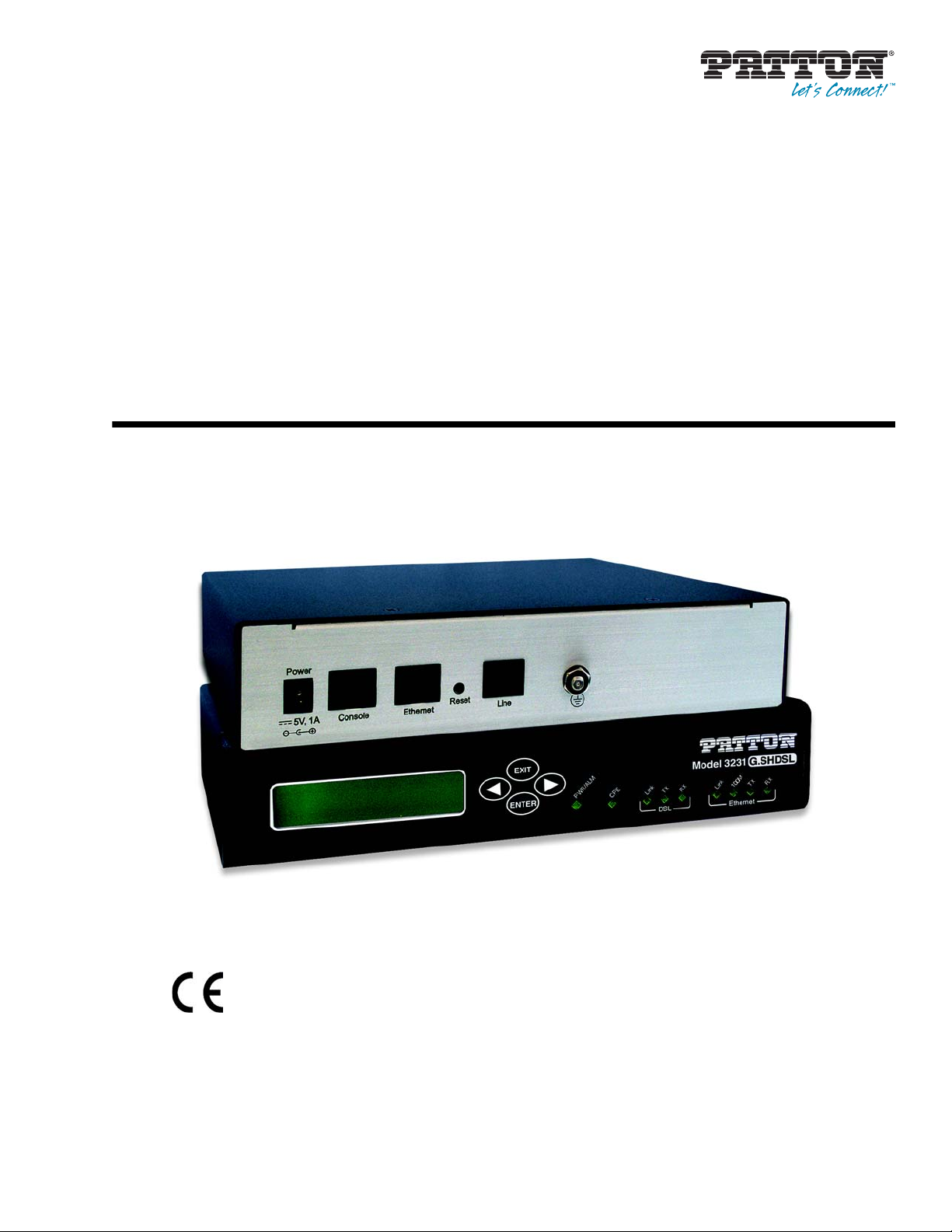
Model 3231
Industrial Ethernet Extender with
LCD Interface
User Manual
Important
This is a Class A device and is intended for use in a light industrial environment. It is not intended nor approved for use in an industrial
or residential environment.
Sales Office: +1 (301) 975-1000
Technical Support: +1 (301) 975-1007
E-mail: support@patton.com
WWW: www.patton.com
Part Number: 07M3231-GS, Rev. B
Revised: February 16, 2012
Page 2

Patton Electronics Company, Inc.
7622 Rickenbacker Drive
Gaithersburg, MD 20879 USA
Tel: +1 (301) 975-1000
Fax: +1 (301) 869-9293
Support: +1 (301) 975-1007
Web: www.patton.com
E-mail: support@patton.com
Trademark Statement
All other trademarks presented in this document are the property of their
respective owners.
Copyright © 2012, Patton Electronics Company. All rights reserved.
The information in this document is subject to change without notice. Patton Electronics assumes no liability for errors that may appear in this document.
Warranty Information
Patton Electronics warrants all Model 3231 components to be free from defects, and
will—at our option—repair or replace the product should it fail within one year from
the first date of shipment.
This warranty is limited to defects in workmanship or materials, and does not cover
customer damage, abuse or unauthorized modification. If this product fails or does not
perform as warranted, your sole recourse shall be repair or replacement as described
above. Under no condition shall Patton Electronics be liable for any damages incurred
by the use of this product. These damages include, but are not limited to, the following: lost profits, lost savings and incidental or consequential damages arising from the
use of or inability to use this product. Patton Electronics specifically disclaims all other
warranties, expressed or implied, and the installation or use of this product shall be
deemed an acceptance of these terms by the user.
Note
Conformity documents of all Patton products can be viewed online at
www.patton.com under the appropriate product page.
Page 3

Summary Table of Contents
1 General information...................................................................................................................................... 13
2 Initial Configuration ..................................................................................................................................... 18
3 G.SHDSL Configuration and Status ............................................................................................................. 28
4 Web Interface Configuration ........................................................................................................................ 34
5 System Management...................................................................................................................................... 39
6 Contacting Patton for assistance ................................................................................................................... 43
A Compliance information .............................................................................................................................. 46
B Specifications ................................................................................................................................................ 49
C RJ-11 non-shielded DSL port ....................................................................................................................... 53
D RJ-45 shielded 10/100 Ethernet port ........................................................................................................... 55
E RS-232 console interface pin assignments .................................................................................................... 57
3
Page 4

Table of Contents
Summary Table of Contents ........................................................................................................................... 3
Table of Contents ........................................................................................................................................... 4
List of Figures ................................................................................................................................................. 7
List of Tables .................................................................................................................................................. 8
About this guide ............................................................................................................................................. 9
Audience................................................................................................................................................................. 9
Structure................................................................................................................................................................. 9
Precautions........................................................................................................................................................... 10
Safety when working with electricity ...............................................................................................................11
General observations .......................................................................................................................................11
Typographical conventions used in this document................................................................................................ 12
General conventions .......................................................................................................................................12
1 General information...................................................................................................................................... 13
Model 3231 Overview...........................................................................................................................................14
Features.................................................................................................................................................................14
Front Panel............................................................................................................................................................15
Menu keypad ..................................................................................................................................................15
LEDs ..............................................................................................................................................................16
Rear Panel .............................................................................................................................................................17
Application............................................................................................................................................................17
2 Initial Configuration ..................................................................................................................................... 18
Introduction..........................................................................................................................................................19
Power up the 3231 ................................................................................................................................................19
AC power-up ..................................................................................................................................................19
Power-up indication ........................................................................................................................................19
Connecting the G.SHDSL port.............................................................................................................................19
Using the LCD Menu ...........................................................................................................................................20
G.SHDSL .......................................................................................................................................................21
LAN ...............................................................................................................................................................21
CPE Config ....................................................................................................................................................21
STP (Spanning Tree Protocol) ........................................................................................................................22
Syslog ..............................................................................................................................................................22
Setting the unit as CO/CPE ..................................................................................................................................23
Configuring the unit as CO ............................................................................................................................23
Configuring the unit as CPE ...........................................................................................................................23
Using the CLI
Connect a PC and log in .................................................................................................................................24
CLI Commands ..............................................................................................................................................24
.......................................................................................................................................................24
G.SHDSL .................................................................................................................................................25
CPE Configuration ...................................................................................................................................25
4
Page 5

Model 3231 User Manual Table of Contents
STP (Spanning Tree Protocol) ..................................................................................................................25
LEDs .........................................................................................................................................................26
Connecting to the Web GUI.................................................................................................................................26
Factory default IP address ...............................................................................................................................26
Modifying the IP address ................................................................................................................................26
Connecting to the local IP network .................................................................................................................27
Logging into the web management interface ...................................................................................................27
3 G.SHDSL Configuration and Status ............................................................................................................. 28
G.SHDSL Configuration ......................................................................................................................................29
G.SHDSL Options .........................................................................................................................................29
G.SHDSL Error Monitor Configuration...............................................................................................................29
Viewing G.SHDSL Status.....................................................................................................................................30
Run-Time Statistics ........................................................................................................................................31
DSL Line Error Counters ...............................................................................................................................32
Local Interface Error Counters ........................................................................................................................32
Clearing Error Counters .................................................................................................................................33
4 Web Interface Configuration ........................................................................................................................ 34
Using the Web Interface........................................................................................................................................35
SNMP...................................................................................................................................................................36
STP (Spanning Tree Protocol) ..............................................................................................................................37
CPE Configuration ...............................................................................................................................................38
5 System Management...................................................................................................................................... 39
Reset for Factory Default.......................................................................................................................................40
Saving the configuration........................................................................................................................................40
Backing up and restoring saved configurations ......................................................................................................40
System Software Upgrade......................................................................................................................................41
Syslog Options in the LCD Menu.........................................................................................................................42
6 Contacting Patton for assistance ................................................................................................................... 43
Introduction..........................................................................................................................................................44
Contact information..............................................................................................................................................44
Patton support headquarters in the USA .........................................................................................................44
Alternate Patton support for Europe, Middle East, and Africa (EMEA) ..........................................................44
Warranty Service and Returned Merchandise Authorizations (RMAs)...................................................................44
Warranty coverage ..........................................................................................................................................44
Out-of-warranty service .............................................................................................................................45
Returns for credit ......................................................................................................................................45
Return for credit policy .............................................................................................................................4
RMA numbers ................................................................................................................................................45
Shipping instructions ................................................................................................................................45
A Compliance information .............................................................................................................................. 46
Compliance ...........................................................................................................................................................47
EMC ...............................................................................................................................................................47
5
5
Page 6

Model 3231 User Manual Table of Contents
Safety ..............................................................................................................................................................47
PSTN Regulatory ............................................................................................................................................47
FCC Part 68 (ACTA) Statement ...........................................................................................................................47
Radio and TV Interference (FCC Part 15) ............................................................................................................47
Industry Canada Notice ........................................................................................................................................48
CE Declaration of Conformity..............................................................................................................................48
Authorized European Representative.....................................................................................................................48
B Specifications ................................................................................................................................................ 49
General characteristics ...........................................................................................................................................50
G.SHDSL characteristics.......................................................................................................................................50
Ethernet ................................................................................................................................................................50
Protocol support....................................................................................................................................................50
Management .........................................................................................................................................................51
10Base-T/100Base-TX interface............................................................................................................................51
Serial connector.....................................................................................................................................................51
Diagnostics............................................................................................................................................................51
Status LEDs...........................................................................................................................................................51
Power/Alarm ...................................................................................................................................................51
CPE ................................................................................................................................................................51
DSL Link ........................................................................................................................................................51
DSL Tx ...........................................................................................................................................................51
DSL Rx ...........................................................................................................................................................51
Ethernet Link ..................................................................................................................................................51
Ethernet 100M ...............................................................................................................................................52
Ethernet Tx ....................................................................................................................................................52
Ethernet Rx .....................................................................................................................................................52
Power ....................................................................................................................................................................52
G.SHDSL Physical connection & Transmission Line .....................................................................................52
Line Coding ....................................................................................................................................................52
Line Interface ........................................................................................................................................................52
Environment .........................................................................................................................................................52
Dimensions ...........................................................................................................................................................52
C RJ-11 non-shielded DSL port ....................................................................................................................... 53
RJ-11 non-shielded DSL port................................................................................................................................54
D RJ-45 shielded 10/100 Ethernet port ........................................................................................................... 55
RJ-45 shielded 10/100 Ethernet port.....................................................................................................................56
E RS-232 console interface pin assignments .................................................................................................... 57
RS-232 console interface pin assignments..............................................................................................................58
6
Page 7

List of Figures
1 Model 3231 . . . . . . . . . . . . . . . . . . . . . . . . . . . . . . . . . . . . . . . . . . . . . . . . . . . . . . . . . . . . . . . . . . . . . . . . . . . 14
2 Model 3231 front panel . . . . . . . . . . . . . . . . . . . . . . . . . . . . . . . . . . . . . . . . . . . . . . . . . . . . . . . . . . . . . . . . . . 15
3 Model 3231 rear panel . . . . . . . . . . . . . . . . . . . . . . . . . . . . . . . . . . . . . . . . . . . . . . . . . . . . . . . . . . . . . . . . . . . 17
4 Rear view of 3231 . . . . . . . . . . . . . . . . . . . . . . . . . . . . . . . . . . . . . . . . . . . . . . . . . . . . . . . . . . . . . . . . . . . . . . . 20
5 Connecting the 3231 to the PC’s serial port . . . . . . . . . . . . . . . . . . . . . . . . . . . . . . . . . . . . . . . . . . . . . . . . . . . 24
6 Connecting the RocketLink-G to the local IP network . . . . . . . . . . . . . . . . . . . . . . . . . . . . . . . . . . . . . . . . . . . 27
7 DSL Error Monitor Configuration . . . . . . . . . . . . . . . . . . . . . . . . . . . . . . . . . . . . . . . . . . . . . . . . . . . . . . . . . . 29
8 DSL Run-time Statistics . . . . . . . . . . . . . . . . . . . . . . . . . . . . . . . . . . . . . . . . . . . . . . . . . . . . . . . . . . . . . . . . . . 31
9 DSL line error counters . . . . . . . . . . . . . . . . . . . . . . . . . . . . . . . . . . . . . . . . . . . . . . . . . . . . . . . . . . . . . . . . . . 32
10 Local Interface Error Counters . . . . . . . . . . . . . . . . . . . . . . . . . . . . . . . . . . . . . . . . . . . . . . . . . . . . . . . . . . . . . 32
11 Clearing the error counters . . . . . . . . . . . . . . . . . . . . . . . . . . . . . . . . . . . . . . . . . . . . . . . . . . . . . . . . . . . . . . . . 33
12 SNMP Settings in the Web GUI . . . . . . . . . . . . . . . . . . . . . . . . . . . . . . . . . . . . . . . . . . . . . . . . . . . . . . . . . . . 36
13 Configuring STP in the Web GUI . . . . . . . . . . . . . . . . . . . . . . . . . . . . . . . . . . . . . . . . . . . . . . . . . . . . . . . . . . 37
14 Configuring the CPE in the Web GUI . . . . . . . . . . . . . . . . . . . . . . . . . . . . . . . . . . . . . . . . . . . . . . . . . . . . . . . 38
15 Reset button . . . . . . . . . . . . . . . . . . . . . . . . . . . . . . . . . . . . . . . . . . . . . . . . . . . . . . . . . . . . . . . . . . . . . . . . . . . 40
16 Backing up and reloaded saved configurations . . . . . . . . . . . . . . . . . . . . . . . . . . . . . . . . . . . . . . . . . . . . . . . . . 41
17 Upgrading software on the 3231 . . . . . . . . . . . . . . . . . . . . . . . . . . . . . . . . . . . . . . . . . . . . . . . . . . . . . . . . . . . . 41
18 Software upgrade protection . . . . . . . . . . . . . . . . . . . . . . . . . . . . . . . . . . . . . . . . . . . . . . . . . . . . . . . . . . . . . . . 42
7
Page 8

List of Tables
1 General conventions . . . . . . . . . . . . . . . . . . . . . . . . . . . . . . . . . . . . . . . . . . . . . . . . . . . . . . . . . . . . . . . . . . . . . 12
2 LCD Menu Keypad - Front Panel . . . . . . . . . . . . . . . . . . . . . . . . . . . . . . . . . . . . . . . . . . . . . . . . . . . . . . . . . . 15
3 Model 3231 LEDs . . . . . . . . . . . . . . . . . . . . . . . . . . . . . . . . . . . . . . . . . . . . . . . . . . . . . . . . . . . . . . . . . . . . . . 16
4 G.SHDSL Menu Options . . . . . . . . . . . . . . . . . . . . . . . . . . . . . . . . . . . . . . . . . . . . . . . . . . . . . . . . . . . . . . . . 21
5 LAN Menu Options . . . . . . . . . . . . . . . . . . . . . . . . . . . . . . . . . . . . . . . . . . . . . . . . . . . . . . . . . . . . . . . . . . . . . 21
6 CPE Config Menu Options . . . . . . . . . . . . . . . . . . . . . . . . . . . . . . . . . . . . . . . . . . . . . . . . . . . . . . . . . . . . . . . 21
7 (STP) Spanning Tree Protocol Menu Options . . . . . . . . . . . . . . . . . . . . . . . . . . . . . . . . . . . . . . . . . . . . . . . . . 22
8 Syslog Menu Options . . . . . . . . . . . . . . . . . . . . . . . . . . . . . . . . . . . . . . . . . . . . . . . . . . . . . . . . . . . . . . . . . . . . 22
9 G.SHDSL - CLI Commands . . . . . . . . . . . . . . . . . . . . . . . . . . . . . . . . . . . . . . . . . . . . . . . . . . . . . . . . . . . . . . 25
10 CPE Config - CLI Commands . . . . . . . . . . . . . . . . . . . . . . . . . . . . . . . . . . . . . . . . . . . . . . . . . . . . . . . . . . . . . 25
11 STP - CLI Commands . . . . . . . . . . . . . . . . . . . . . . . . . . . . . . . . . . . . . . . . . . . . . . . . . . . . . . . . . . . . . . . . . . . 25
12 LEDs - CLI Commands . . . . . . . . . . . . . . . . . . . . . . . . . . . . . . . . . . . . . . . . . . . . . . . . . . . . . . . . . . . . . . . . . . 26
8
Page 9

About this guide
This guide describes installing and operating the Patton Electronics Model 3231 Industrial Ethernet Extender
with LCD interface.
Audience
This guide is intended for the following users:
• Operators
• Installers
• Maintenance technicians
Structure
This guide contains the following chapters and appendices:
• Chapter 1 on page 13 provides information about 3231 features and capabilities.
• Chapter 2 on page 18 contains an overview describing 3231 operation and configuration.
• Chapter 3 on page 28 provides describes how to configure and monitor G.SHDSL.
• Chapter 4 on page 34 provides describes how to configure settings using the web interface.
• Chapter 5 on page 39 describes how to save the configuration, reset the 3231 to the factory default condi-
tion, and upgrade the system software.
• Chapter 6 on page 43 contains information on contacting Patton technical support for assistance.
• Appendix A on page 46 contains compliance information for the 3231.
• Appendix B on page 49 contains specifications for the 3231.
• Appendix C on page 53 describes the DSL port pin-out.
• Appendix D on page 55 describes the Ethernet port pin-out.
• Appendix E on page 57 describes the Console port pin-out.
For best results, read the contents of this guide before you install the 3231.
9
Page 10
Model 3231 User Manual
Precautions
Notes, cautions, and warnings, which have the following meanings, are used throughout this guide to help you
become aware of potential problems. Warnings are intended to prevent safety hazards that could result in personal injury. Cautions are intended to prevent situations that could result in property damage or
impaired functioning.
Note
IMPORTANT
CAUTION
CAUTION
WARNING
WARNING
A note presents additional information or interesting sidelights.
The alert symbol and IMPORTANT heading calls attention to
important information.
The alert symbol and CAUTION heading indicate a potential hazard. Strictly follow the instructions to avoid property damage.
The shock hazard symbol and CAUTION heading indicate a
potential electric shock hazard. Strictly follow the instructions to
avoid property damage caused by electric shock.
The alert symbol and WARNING heading indicate a potential safety hazard.
Strictly follow the warning instructions to avoid personal injury.
The shock hazard symbol and WARNING heading indicate a potential electric
shock hazard. Strictly follow the warning instructions to avoid injury caused
by electric shock.
10
Page 11

Model 3231 User Manual
Safety when working with electricity
• This device contains no user serviceable parts. The equipment shall be
returned to Patton Electronics for repairs, or repaired by qualified service
WARNING
personnel.
• AC Powered Units: The external power adaptor shall be a listed Limited
Power Source. Ensure that the power cable used meets all applicable standards for the country in which it is to be installed, and that it is connected
to a wall outlet which has earth ground. The mains outlet that is utilized to
power the device shall be within 10 feet (3 meters) of the device, shall be
easily accessible, and protected by a circuit breaker.
• DC Powered Units: The interconnecting cables shall be rated for proper
voltage, current, anticipated temperature, flammability, and mechanical
serviceability.
• Hazardous network voltages are present in WAN ports, regardless of
whether power to the unit is ON or OFF. To avoid electric shock, use caution when near WAN ports. When detaching the cables, detach the end
away from the device first.
• Do not work on the system or connect or disconnect cables during periods
of lightning activity.
In accordance with the requirements of council directive 2002/
96/EC on Waste of Electrical and Electronic Equipment (WEEE),
ensure that at end-of-life you separate this product from other
waste and scrap and deliver to the WEEE collection system in
your country for recycling.
General observations
• Clean the case with a soft slightly moist anti-static cloth
• Place the unit on a flat surface and ensure free air circulation
• Avoid exposing the unit to direct sunlight and other heat sources
• Protect the unit from moisture, vapors, and corrosive liquids
11
Page 12
Model 3231 User Manual
Typographical conventions used in this document
This section describes the typographical conventions and terms used in this guide.
General conventions
The procedures described in this manual use the following text conventions:
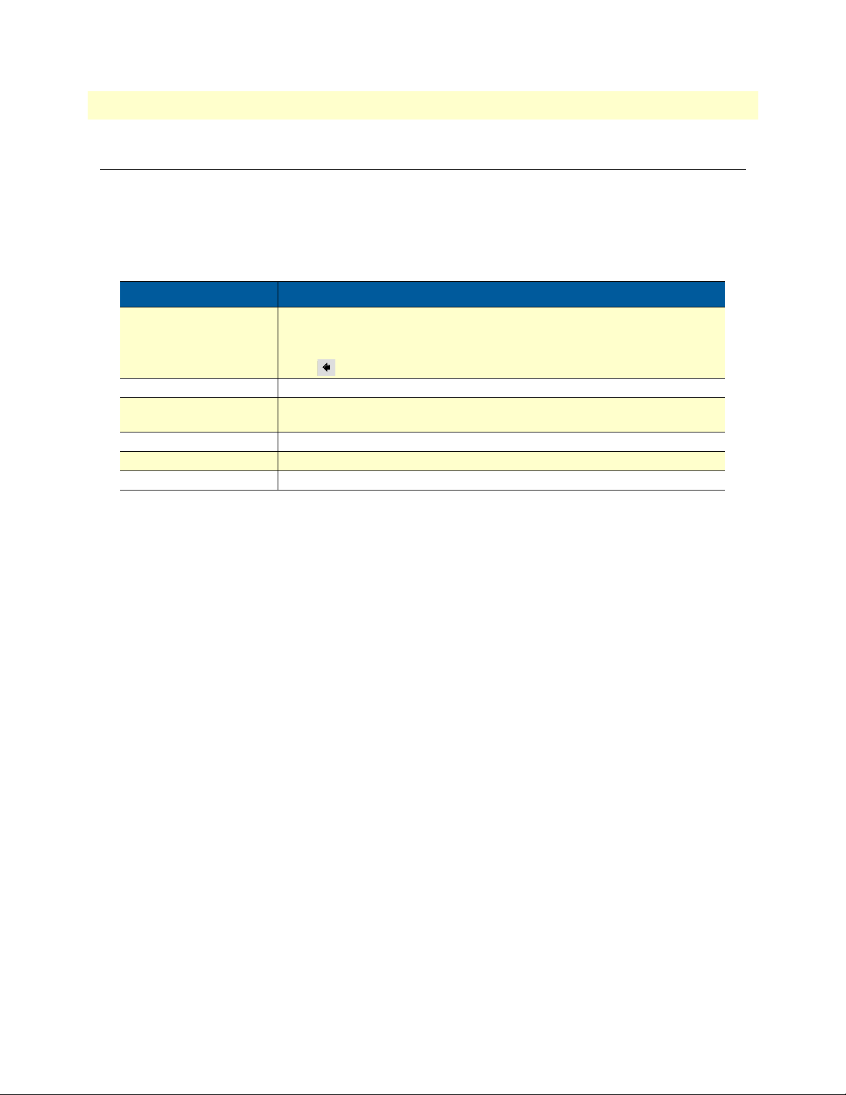
Table 1. General conventions
Convention Meaning
Garamond blue type
Futura bold type Commands and keywords are in boldface font.
Futura bold-italic type Parts of commands, which are related to elements already named by the user, are
Italicized Futura type Variables for which you supply values are in italic font
Futura type Indicates the names of fields or windows.
Garamond bold type Indicates the names of command buttons that execute an action.
Indicates a cross-reference hyperlink that points to a figure, graphic, table, or section heading. Clicking on the hyperlink jumps you to the reference. When you
have finished reviewing the reference, click on the Go to Previous View
button in the Adobe® Acrobat® Reader toolbar to return to your starting point.
in boldface italic font.
12
Page 13

Chapter 1 General information
Chapter contents
Model 3231 Overview...........................................................................................................................................14
Features.................................................................................................................................................................14
Front Panel............................................................................................................................................................15
Menu keypad ..................................................................................................................................................15
LEDs ..............................................................................................................................................................16
Rear Panel .............................................................................................................................................................17
Application............................................................................................................................................................17
13
Page 14
Model 3231 User Manual 1 • General information
Model 3231 Overview
The Patton Electronics Model 3231 Industrial Ethernet Extender with LCD provides high speed 2-wire connectivity to ISPs, PTTs, and enterprise environments using Symmetrical High-data-rate Digital Subscriber
Line (G.SHDSL) technology.
The Model 3231 provides a 10/100BaseT Ethernet interface on a shielded RJ-45 jack, the DSL on an RJ-11
jack, and the RS-232 console port on an RJ-45 jack.
As a symmetric, full-duplex NTU, the DSL port offers equal data rates in both directions over a single twisted
pair using TC-PAM modulation. Line connection is made through the RJ-11 jack. Standard versions of Model
3231 are powered by a UI (universal 100–240 VAC) supply.
Figure 1. Model 3231
Features
• LCD panel for easy configuration and monitoring
• Symmetrical high data-rate DSL (G.SHDSL)
• Data rates up to 4.6Mbps in 64-kbps intervals
• 10Base-T/100Base-TX Ethernet interface
• RS-232 console port for management and configuration
• Built-in testing and diagnostics
• Interoperable with other Patton G.SHDSL modems
• Configurable as remote (CP) units
• Configurable as central (CO) units to operate back-to-back
• Front-panel status indicators
• CE marked
Model 3231 Overview 14
Page 15
Model 3231 User Manual 1 • General information
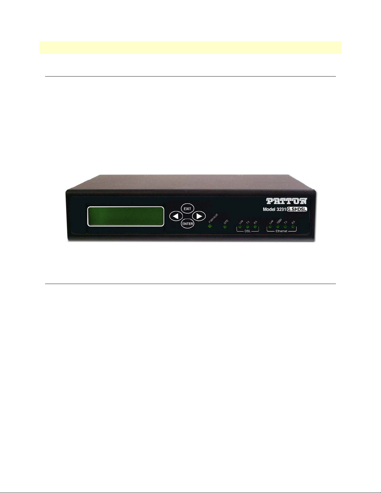
Front Panel
EXIT
ENTER
PWR/ALM
TX
Link
CPE
DSL Ethernet
EXIT
ENTER
PWR/ALM
CPE
Link
TX
RX
DSL
Link
RX
Link
100M
TX
Ethernet
RX
100M
RX
TX
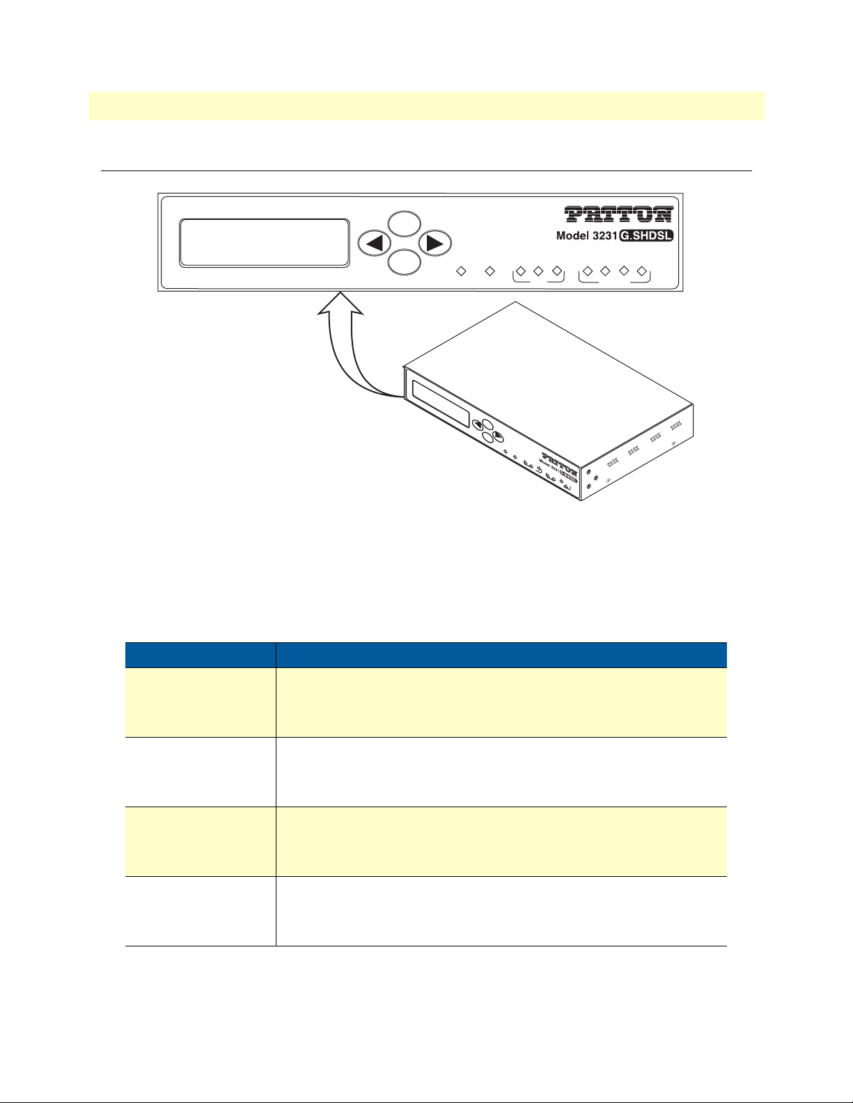
Figure 2. Model 3231 front panel
Menu keypad
The Model 3231 contains an LCD menu and keypad, located on the front panel, for configuring the unit.
The four keys on the menu keypad and their functions are:
Table 2. LCD Menu Keypad - Front Panel
Key Purpose
ENTER
•
Select the current item
•
Advance into a submenu
•
Confirm changes in a menu item
EXIT
LEFT ARROW
RIGHT ARROW
Note
•
Deselect the current item
•
Exit out of a submenu
•
Cancel a change in a menu item
•
Move to the previous item in a menu
•
Move to the previous value for an item in a menu
•
Increment the current digit or character in an IP address or string
•
Move to the next item in a menu
•
Move to the next value for an item in a menu
•
Select the next digit or character to change in an IP address or string
For information on how the LCD menu is structured, see “Using the
LCD Menu” on page 20.
Front Panel 15
Page 16
Model 3231 User Manual 1 • General information
LEDs
The Model 3231 contains nine LEDs on the front panel. All LEDs will blink twice when the unit is first powered on.
Table 3. Model 3231 LEDs
LED Color Purpose
PWR/ALM Green/Red
CPE Green
DSL Link Green
DSL TX Green
DSL RX Green
Ethernet Link Green
•
Green when power is applied and alarm state is clear
•
Red when alarm state is not clear
•
On when configured as DSL CPE
•
Off when configured as DSL CO
*Note: The Restart DSL menu item must be selected after changing between CO and CPE in order for the LED to change. *
•
On when DSL link is up
•
Flashes when DSL link is connecting
•
Off when DSL link is down
•
Flashes when transmitting data over DSL
•
Flashes when receiving data over DSL
•
On when Ethernet link is up
Ethernet 100M Green
Ethernet TX Green
Ethernet RX Green
Note
You can test the operation of certain LEDS using the CLI.
For more information, see “CLI Commands” on page 24.
•
Off when Ethernet link is down
•
On when Ethernet link negotiates to 100 Mbps
•
Off when Ethernet link negotiates to 10 Mbps
•
Flashes when transmitting an Ethernet packet
•
Flashes when receiving an Ethernet packet
Front Panel 16
Page 17
Model 3231 User Manual 1 • General information
Rear Panel
Power
5V, 1A
Console
Ethernet
Reset
Line
Model 3231
Power
5V, 1A
Power
Console
Console
RS-232 port
Ethernet
Ethernet
RJ-45 port
Reset
Reset
button
Line
Ground
G.SHDSL
RJ-11 port
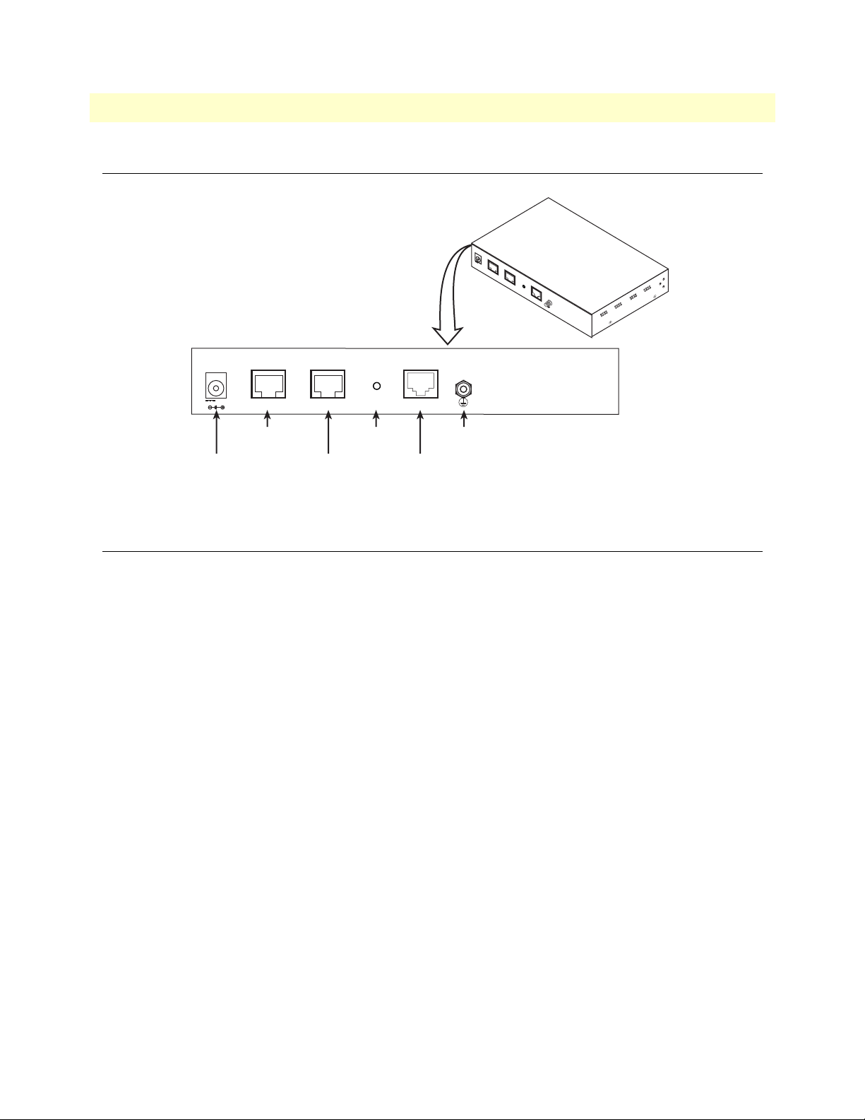
Figure 3. Model 3231 rear panel
Application
The Model 3231 is used as a network extender using a PPPoH bridge over DSL. PPPoH is an Ethernet extension because the same logical LAN exists at both ends of the modems and only bridging is required. PPPoH is
network extension in the more general sense since a different logical network is on each end of the modems.
Rear Panel 17
Page 18

Chapter 2 Initial Configuration
Chapter contents
Introduction..........................................................................................................................................................19
Power up the NTU ...............................................................................................................................................19
AC power-up ..................................................................................................................................................19
Power-up indication ........................................................................................................................................19
Connecting the G.SHDSL port.............................................................................................................................19
Using the LCD Menu ...........................................................................................................................................20
G.SHDSL .......................................................................................................................................................21
LAN ...............................................................................................................................................................21
CPE Config ....................................................................................................................................................21
STP (Spanning Tree Protocol) ........................................................................................................................22
Syslog ..............................................................................................................................................................22
Setting the unit as CO/CPE ..................................................................................................................................23
Configuring the unit as CO ............................................................................................................................23
Configuring the unit as CPE ...........................................................................................................................23
Using the CLI .......................................................................................................................................................24
Connect a PC and log in .................................................................................................................................24
CLI Commands ..............................................................................................................................................24
G.SHDSL .................................................................................................................................................25
CPE Configuration ...................................................................................................................................25
STP (Spanning Tree Protocol) ..................................................................................................................25
LEDs .........................................................................................................................................................26
Connecting to the Web GUI.................................................................................................................................26
Factory default IP address ...............................................................................................................................26
Modifying the IP address ................................................................................................................................26
Connecting to the local IP network .................................................................................................................27
Logging into the web management interface ...................................................................................................27
18
Page 19

Model 3231 User Manual 2 • Initial Configuration
Introduction
The Model 3231 is configured through the LCD menu on the front panel. More advanced features may be
configured through the Web GUI interface.
The 3231 is Plug ‘n’ Play with the Model 3096RC G.SHDSL concentrator card or compatible
G.SHDSL card.
Power up the 3231
Your 3231 comes with an external AC adaptor with detachable power cord.
Ensure that the power cable used with the external power adapter meets all
applicable standards for the country in which it is to be installed, and that it is
WARNING
AC power-up
1. Connect female plug of the AC power cord to the AC adaptor provided.
2. Connect the barrel-type connector of the AC adaptor to the barrel-type power jack on the
3231.
connected to a wall outlet which has earth ground.
3. Insert the male plug of the AC power cord into an AC power outlet (100–240 VAC).
There are no user-servicable parts in the power supply section of
the Model 3231. Fuse replacement should only be performed by
WARNING
qualified service personnel. See Chapter 6,
for assistance”
on page 43.
“Contacting Patton
Power-up indication
The Power LED is lit while the unit is powering up.
Connecting the G.SHDSL port
1. Obtain single-twisted-pair cable with an RJ-11 plug connector at each end.
2. Plug one end of the cable into the (yellow) RJ-11 socket (labelled Line) on the 3231. (See figure 4.)
3. Plug the other end of the cable into the RJ-11 wall socket that provides your G.SHDSL service.
4. From the top level menu on the LCD panel, use the Left and Right arrow keys to navigate to G.SHDSL,
then press ENTER. See “G.SHDSL” on page 21 for configuration options.
Note
If two Model 3231 units are connected back-to-back, one must be configured as CO, the other as CPE. See “Setting the unit as CO/CPE” on
page 23.
5. The WAN Link LED will flash while in the process of establishing a link. The LED will be on constantly
once a valid DSL connection is established.
Introduction 19
Page 20

Model 3231 User Manual 2 • Initial Configuration
Power
5V, 1A
Console
Ethernet
Reset
Line
Figure 4. Rear view of 3231
Using the LCD Menu
The following sections are options in the top level menu on the LCD interface:
• “G.SHDSL” on page 21
Use this menu to configure the G.SHDSL link including line rate, I-bits, mode, annex, transmit gain, and
the ethernet link.
• “LAN” on page 21
Use this menu to configure the LAN IP address, netmask, and default gateway.
• “CPE Config” on page 21
Use this menu on the CO unit to configure the CPE unit.
• “STP (Spanning Tree Protocol)” on page 22
Use this menu to configure STP. (STP prevents loops from occurring in a network).
• “Syslog” on page 22
Use this menu to configure the system, including the host IP address, facility settings, system password,
alarms, saving the current configuration, and the LCD screen contrast.
• Password
If a password is set, a user must enter the password to access the LCD submenus. Enter an empty string to
remove the password.
• Clear Alarms
Clear DSL, Ethernet, and any other alarm indications.
• Save Config
Save the current configuration to flash.
• LCD Contrast
Adjust the contrast of the LCD screen. Use the Left and Right Arrown keys to adjust the contrast, then
press the Enter key to save your changes.
Using the LCD Menu 20
Page 21

Model 3231 User Manual 2 • Initial Configuration
G.SHDSL
Table 4. G.SHDSL Menu Options
Submenu Options
Line Rate 192 kbps – 4608 kbps
I-bits 0 – 7
Mode CO or CPE
Annex A or B
Transmit Gain -1.6 dB – 1.6 dB
Eth Link Kill Enabled or Disabled
If enabled, the Ethernet link will go down if the DSL link goes down.
Noise Margin View the noise margin in dB. (This option is not configurable).
Restart DSL Reconfigure DSL and retrain link.
This must be selected after any of the G.SHDSL options are changed (except Eth
Link Kill, which takes effect immediately).
LAN
Table 5. LAN Menu Options
Submenu Options
IP Address Set and modify the LAN IP address
Netmask Set and modify the LAN netmask
Default GW Set to 000.000.000.000 to remove the default gateway
CPE Config
Use this menu on the CO unit to configure the CPE unit.
(None of the items in this menu may be configured if this unit is set as the CPE).
Table 6. CPE Config Menu Options
Submenu Options
CPE Cfg State Wait until this state reaches Idle before configuring any of the CPE
options. This may take 1-2 minutes after the DSL link comes up. Any changes to
the CPE options that are made before reaching the Idle state will be lost.
CPE Line Rate 192 kbps – 4608 kbps
CPE IP Address Set and modify the CPE IP address
CPE Netmask Set and modify the CPE netmask
CPE Default GW Set to 000.000.000.000 to remove the CPE’s default gateway
Get CPE Config Request the CPE to report its configuration to this unit.
This is unnecessary because the CO will always reuqest the CPE’s configuration
when the link comes up.
Set CPE Config Send new configuration to the CPE.
This must be selected after changing any of the parameters in this menu.
Using the LCD Menu 21
Page 22

Model 3231 User Manual 2 • Initial Configuration
STP (Spanning Tree Protocol)
Table 7. (STP) Spanning Tree Protocol Menu Options
Submenu Options
Enabled Enable or Disable STP
Fwd Delay 4 – 30 seconds
Hello Time 1 – 10 seconds
Max Age 6 – 40 seconds
Syslog
Table 8. Syslog Menu Options
Submenu Options
Host IP Set the external syslog server that the unit logs to.
Facility disable / user / mail / daemon / auth / syslog / lpr / news / uucp / cron
authpriv / ftp / local0 / local1 / local2 / local3 / local4 / local5 /
local6 / local7
Using the LCD Menu 22
Page 23

Model 3231 User Manual 2 • Initial Configuration
Setting the unit as CO/CPE
Configuring the unit as CO
To set the unit as CO:
1. From the top level menu on the LCD panel, use the Left and Right arrow keys to navigate to G.SHDSL,
and press ENTER.
2. Use the arrow keys to highlight Mode, then press ENTER.
3. Select CO, and press ENTER.
4. To activate the unit as CO, select Restart DSL from the G.SHDSL menu, and press ENTER.
The CPE LED on the front panel should not be lit.
Configuring the unit as CPE
To set the unit as CPE:
1. From the top level menu on the LCD panel, use the Left and Right arrow keys to navigate to G.SHDSL,
and press ENTER.
2. Use the arrow keys to highlight Mode, then press ENTER.
3. Select CPE, and press ENTER.
4. To activate the unit as CPE, select Restart DSL from the G.SHDSL menu, and press ENTER.
The CPE LED on the front panel should be lit.
Note
Do not use the CPE Config options in the LCD menu on the CPE unit for
CPE configuration. Use the Model 3231 that you set as the CO to configure
the CPE unit. See “CPE Config” on page 21 for CPE configuration options.
Setting the unit as CO/CPE 23
Page 24

Model 3231 User Manual 2 • Initial Configuration
Using the CLI
The Model 3231 may be configured through the CLI, although basic settings should be configured through
the LCD menu on the unit.
Note
Use the LCD panel menu to primarily configure the unit. Refer to “Using
the LCD Menu” on page 20 for configuration options in the LCD menu.
Connect a PC and log in
Use an RS-232/Ethernet cable and DB9-RJ45 adapter to connect a PC’s serial port to the 3231’s Console port
(see figure 5).
The interconnecting cables shall be acceptable for external use
and shall be rated for the proper application with respect to voltage, current, anticipated temperature, flammability, and
CAUTION
PC with
terminal emulator
mechanical serviceability.
Serial port
Model 3231
Connect to Console port
Power
5V, 1A
Console
Ethernet
Reset
Line
Figure 5. Connecting the 3231 to the PC’s serial port
1. Start a HyperTerminal session on the PC using the settings:
9600 bps, 8 data bits, no parity, 1 stop bit, no flow control
2. Log in to the 3231 using the factory-default login (superuser) and password (superuser):
CLI Commands
The following settings can be configured through the CLI:
• “G.SHDSL” on page 25
Use these commands to configure the timeslots and i-bits for the G.SHDSL link.
• “CPE Configuration” on page 25
Use these commands to configure the CPE unit, including the line rate, IP address, netmask, and default
gateway.
• “STP (Spanning Tree Protocol)” on page 25
Use these commands to configure the forward delay time, hello time, and maximum age for STP.
• “LEDs” on page 26
Use this command to test the operation of specific LEDs.
Using the CLI 24
Page 25

Model 3231 User Manual 2 • Initial Configuration
G.SHDSL
Table 9. G.SHDSL - CLI Commands
Command Explanation
gshdsl set dslrateTS <#timelots> Set the number of timeslots that each DSL frame will
carry. The DSL data rate will be (64 kbps x
#timeslots) + #ibits.
gshdsl set datarateI <#ibits> Set the number of i-bits that each DSL frame will
carry. The DSL data rate will be (64 kbps x
#timeslots) + #ibits.
gshdsl set action start Force the DSL link to retrain. The data rate settings
will not take effect until this command is issued.
CPE Configuration
Table 10. CPE Config - CLI Commands
Command Explanation
cpeconfig show Show the CPE’s configuration
cpeconfig set dslrateTS <3-72> Set the CPE’s line rate. This will not be sent to the CPE
until the cpeconfig action set command is run.
cpeconfig set ipaddress <A.B.C.D> Set the CPE’s IP address. This will not be sent to the
CPE until the cpeconfig action set command is
run.
cpeconfig set netmask <A.B.C.D> Set the CPE’s netmask. This will not be sent to the CPE
until the cpeconfig action set command is run.
cpeconfig set defaultgw <A.B.C.D> Set the CPE’s default gateway. This will not be sent to
the CPE until the cpeconfig action set command is
run.
cpeconfig action get Get the CPE’s configuration. This will automatically
happen each time the DSL link comes up.
cpeconfig action set Command the CPE to configure itself with the desired
line rate, IP address, netmask, and default gateway.
STP (Spanning Tree Protocol)
Table 11. STP - CLI Commands
Command Explanation
bridge show Show STP configuration.
bridge set spanning {enabled | disabled} Enable/Disable STP.
bridge set spanning forwarddelay <4-30> Set STP forward delay time in seconds.
bridge set spanning hellotime <1-10> Set STP hello time in seconds.
bridge set spanning maxage <6-40> Set STP max age in seconds.
Using the CLI 25
Page 26

Model 3231 User Manual 2 • Initial Configuration
LEDs
Table 12. LEDs - CLI Commands
Command Explanation
console process led message <led> <message>
This command may be used to test the operation of
specific LEDs. It should not be used in normal operation.
This command causes the specified message to be
played on the specified led. The led may be any number, 0-9. The message is a string that may include
any of the following characters:
•‘D’ or ‘d’: Set the LED to its default on/off state.
•‘.’: Turn the LED off.
•‘*’: Turn the LED on.
•‘X’ or ‘x’: Toggle the LED.
For example, the command:
console process led message 0 *.*.*.*.*.
will cause the power LED to blink on then off 5 times.
Connecting to the Web GUI
Note
Factory default IP address
The 3231 is shipped with a factory-configured IP address assigned to the Ethernet LAN port (green outline).
The address is 192.168.200.10. In most cases, you must change the address to be on the same subnet as your
PC, as described in the procedures below. If you are not sure which IP address to use for your installation, contact your network administrator.
Modifying the IP address
1. From the top level menu on the LCD panel, use the Left and Right arrow keys to navigate to LAN, then
press ENTER.
2. In the LAN menu, navigate to IP Address, and press ENTER.
3. Enter the IP address. Use the Left arrow key to increase a number, and use the Right arrow key to move to
the next number to change. The number that is currently selected will be underlined. When you are done
entering the new IP address, press ENTER.
Use the LCD panel menu to configure the unit. Refer to “Using the LCD
Menu” on page 20 for configuration options in the LCD menu.
The Web GUI should be used for advanced configuration and advanced
monitoring only.
Connecting to the Web GUI 26
Page 27

Model 3231 User Manual 2 • Initial Configuration
Connecting to the local IP network
Now you can connect the 3231 to your local IP network and access advanced configuration features from your
PC using a standard web browser.
Connect the 3231’s Ethernet port (green) to the same Ethernet segment as your PC (see figure 6). The front-
panel Ethernet Link LED should turn on. If it does not, press the rear-panel MDI-X switch so that the Ethernet
Link LED illuminates.You can check the connection with the ping command.
Model 3231
Power
PC
Ethernet port
Connect to Ethernet port
Figure 6. Connecting the RocketLink-G to the local IP network
5V, 1A
Console
Ethernet
Reset
Line
Logging into the web management interface
You can access the web management graphical user interface (GUI) using a standard web browser (such as
Netscape Browser, Mozilla Firefox, or Internet Explorer).
1. At your PC, open a web browser and enter the IP address you assigned to the unit’s Ethernet LAN port in
the section “Modifying the IP address” on page 26. (In this example, 10.10.4.10.).
2. Log in to the web management home page using the username superuser and the password superuser.
Note
See Chapter 4, “Web Interface Configuration” on page 34 for configuring
features through the web interface, including SNMP, CPE Configuration,
and STP (Spanning Tree Protocol).
Connecting to the Web GUI 27
Page 28

Chapter 3 G.SHDSL Configuration and Status
Chapter contents
G.SHDSL Configuration ......................................................................................................................................29
G.SHDSL Options .........................................................................................................................................29
G.SHDSL Error Monitor Configuration...............................................................................................................29
Viewing G.SHDSL Status.....................................................................................................................................30
Run-Time Statistics ........................................................................................................................................31
DSL Line Error Counters ...............................................................................................................................32
Local Interface Error Counters ........................................................................................................................32
Clearing Error Counters .................................................................................................................................33
28
Page 29

Model 3231 User Manual 3 • G.SHDSL Configuration and Status
G.SHDSL Configuration
Use the LCD panel to configure G.SHDSL. From the top level menu on the LCD panel, use the Left and
Right arrows to navigate to G.SHDSL, and press ENTER. The following options are available in the
G.SHDSL submenu:
Note
After you change a G.SHDSL option, you must select Restart DSL (in the
G.SHDSL menu) and press ENTER to activate your changes. This must be
selected after changing any G.SHDSL option except Eth Link Kill, which
takes effect immediately.
G.SHDSL Options
• Mode: CO or CPE. (See “Setting the unit as CO/CPE” on page 23 for more information).
• Annex: A or B.
• Line Rate (kbps): This selects the desired DSL data rate between 192 kbps – 4608 kbps. Use the Left arrow
key to move through the options.
• Tx Gain: Select an option between -1.6 dB – 1.6 dB. Use the Left arrow key to move through the options.
• Eth Link Kill: Enable or Disable. If enabled, the Ethernet link will go down if the DSL link goes down.
• Restart DSL: Reconfigure DSL and retrain the link. This must be selected after any of the G.SHDSL
options are changed (except Eth Link Kill, which takes effect immediately).
G.SHDSL Error Monitor Configuration
You can use the Web GUI to monitor the DSL error counters. (See “Connecting to the Web GUI” on
page 26)
Note
It is NOT reccommended that you configure G.SHDSL through the Web
GUI. Use the LCD panel menu to configure G.SHDSL options, and use the
Web GUI for advanced status monitoring only.
The DSL Error Monitor provides various statistics for the DSL line. The monitor parameters are configured
here. The error counters are also cleared from this menu.
Figure 7. DSL Error Monitor Configuration
G.SHDSL Configuration 29
Page 30

Model 3231 User Manual 3 • G.SHDSL Configuration and Status
The following shows the relationship of the DSL Error Monitor parameters:
Startup Delay Interval #1 Interval #2 …
ÕStart Up DelayÖ ÕInterval Time (sec)Ö ÕInterval Time (sec)Ö ÕInterval Time (sec)Ö ÕInterval Time (sec)Ö
Interval #Total
Intervals
The DSL error monitor inspects intervals to see if they have met the error threshold (Max Interval Errors). If
the error monitor finds a certain number (Interval Count) of intervals that meet or exceed the error threshold,
it will restart the DSL link. The error monitor will wait (Start Up Delay) seconds after the DSL link comes up
before it begins monitoring errors. After the startup delay, it will check the number of errors that have occurred
during each (Interval Time) seconds to see if they meet the error threshold. The error monitor inspects (Total
Intervals) intervals before it stops.
Note
Setting Max Interval Errors to 0 disables the error monitor and setting
Total Intervals to 0 causes the error monitor to run continuously.
The following commands configure the error monitor:
• Error Monitor Max Interval Errors: Sets the number of errors allowed in an interval causes it to be consid-
ered an errored interval. If this is set to 0, then the error monitor is disabled.
• Error Monitor Interval Time (sec): Sets the length of each interval.
• Error Monitor Interval Count: Sets the number of errored intervals that causes the DSL link to restart.
• Error Monitor Total Intervals: Sets the number of intervals to inspect for errors before disabling the error
monitor. If this is set to 0, then the error monitor will run continuously.
• Error Monitor Start Up Delay: Sets the number of seconds to wait after the DSL link comes up before the
error monitor starts inspecting intervals.
Viewing G.SHDSL Status
You can view the status of the G.SHDSL link through the Web GUI. (See “Connecting to the Web GUI” on
page 26). Selecting the Status hyperlink on the Configuration Menu provides the web page containing the
G.SHDSL status and the Bridged PPP link status. The G.SHDSL Status is divided into three groups, Run-
Time Statistics, DSL Line Error Counters, and Local Interface Error Counters.
Note
It is NOT reccommended that you configure G.SHDSL through the Web
GUI. Use the LCD panel menu to configure G.SHDSL options, and use the
Web GUI for advanced status monitoring only.
Viewing G.SHDSL Status 30
Page 31

Model 3231 User Manual 3 • G.SHDSL Configuration and Status
Run-Time Statistics
The Run-Time Statistics provide the state and relative health of the DSL link. The statistical parameters
are described.
Figure 8. DSL Run-time Statistics
• G.SHDSL State: The link may be in one of these states, Deactivated, In Progress, or Normal Operation.
• Connected: If there is a valid physical DSL link, the field is TRUE. If not, it displays FALSE.
• Loss Of Signal: Indicates Signal Loss or Signal Found.
• Loss of Sync: Indicates whether the Sync Word is synchronized.
• DLS Sync State: The sync state of the DSL link may be Out of Sync, In Sync, Acquiring Sync, or Loss of Sync.
• Noise Margin (dB): The maximum tolerable increase in external noise power that still allows for BER of
7
less than 1 x 10–
Note
.
G.SHDSL State vs. DSL Sync State—The G.SHDSL State describes
whether the DSL is training (in progress), linked (success), deactivated,
or idle.
The DSL Sync State describes whether no sync words have been found (out
of sync), whether there are no sync word errors (in sync), or whether we are
transitioning from out of sync to in sync (acquiring sync) or vice versa (losing sync). Typically, when the link is training, the sync state goes from out of
sync to acquiring sync to in sync.
Viewing G.SHDSL Status 31
Page 32

Model 3231 User Manual 3 • G.SHDSL Configuration and Status
DSL Line Error Counters
Five counters display how many Loss of Sync’s have occurred, CRC Errors, SEGD Errors, SEGA Errors, and Loss
of Delineation. Loss of Sync and CRC Errors are the most commonly used statistics in normal
performance evaluation.
Figure 9. DSL line error counters
• Loss of Sync: The number of times that synchronization has been lost since the error counters have
been cleared.
• CRC Errors: Shows the number of CRC errors that have occurred since either startup or the last time that
error counters were cleared.
• SEGD Errors: The number of SEGD errors in the DSL link.
• SEGA Errors: The number of SEGA errors in the DSL link.
• Loss of Delineation: The number of time that delineation has been lost.
Local Interface Error Counters
These counters are rarely used for normal performance evaluation or troubleshooting. However they are shown
and listed here.
Figure 10. Local Interface Error Counters
Viewing G.SHDSL Status 32
Page 33

Model 3231 User Manual 3 • G.SHDSL Configuration and Status
Clearing Error Counters
The error counters may be cleared in the Configuration web page or here in the Status web page. Select Clear
All Counters and click on the Submit button.
Figure 11. Clearing the error counters
Viewing G.SHDSL Status 33
Page 34

Chapter 4 Web Interface Configuration
Chapter contents
Using the Web Interface........................................................................................................................................35
SNMP...................................................................................................................................................................36
STP (Spanning Tree Protocol) ..............................................................................................................................37
CPE Configuration ...............................................................................................................................................38
34
Page 35

Model 3231 User Manual 4 • Web Interface Configuration
Using the Web Interface
The Model 3231 provides a web interface for advanced configuration of:
• “SNMP” on page 36
• “STP (Spanning Tree Protocol)” on page 37
• “CPE Configuration” on page 38
Note
Note
Note
The Web GUI should be used for advanced configuration and advanced
monitoring only. Use the LCD panel menu to configure the unit. Refer to
“Using the LCD Menu” on page 20 for configuration options in the LCD
menu.
For information on how to connect to the web interface, see “Connecting to
the Web GUI” on page 26.
For information on how to monitor the G.SHDSL link through the web
interface, see Chapter 3, “G.SHDSL Configuration and Status” on page 28.
Using the Web Interface 35
Page 36

Model 3231 User Manual 4 • Web Interface Configuration
SNMP
You can use the Web GUI to configure SNMP. (See “Connecting to the Web GUI” on page 26).
Note
It is NOT reccommended that you configure basic options through the Web
GUI. Use the LCD panel menu to configure basic options such as
G.SHDSL, and use the Web GUI for advanced configuration only, such as
SNMP.
This section describes how to configure the SNMP server so that an agent can monitor the unit via SNMP. To
get to the SNMP configuration page in the Web GUI, click on System Configuration > SNMP Daemon on
the left navigation menu.
Figure 12. SNMP Settings in the Web GUI
From this page, you can configure the following options:
• Static Variables: Set the system MIB variables.
• Community Table: Add/delete communities that have access to this unit. The password is the community
string. If the management IP is 0.0.0.0, all requests from that community will be accepted regardless of the
originating IP address.
• Trap Table: Add/delete trap daemons. The IP address is the address of the PC running a trap daemon. The
unit will send SNMPv1 traps on DSL and Ethernet link up and down events.
• Save SNMP Configuration: Save SNMP configuration. For SNMP configuration to persist across reboots,
click the Save button on this page, and then, save the system configuration. Both must be done in that
order.
SNMP 36
Page 37

Model 3231 User Manual 4 • Web Interface Configuration
STP (Spanning Tree Protocol)
This section describes how to configure Spanning Tree Protocol through the web interface. To get to the STP
configuration page in the Web GUI, click on Services Configuration > STP on the left navigation menu.
Note
Use the LCD panel menu to configure basic options. See “STP (Spanning
Tree Protocol)” on page 22 for information on configuring STP through the
LCD menu.
Figure 13. Configuring STP in the Web GUI
To configure STP through the Web GUI:
1. Select Enabled from the Enabled drop-down menu to enable STP.
2. Enter the Forward Delay time (4–30 seconds).
3. Enter the Hello Time (1–10 seconds).
4. Enter the Max Age (6–40 seconds).
5. Click Update.
Note
When enabling STP, the unit will go into the discovery state for a period of
time (typically about 30-60 seconds) until it reaches the forwarding state.
While in the discovery state, the unit will not pass traffic over the Ethernet
port. For this reason, the web page will not respond for the next several seconds. This is normal, and the web page will respond when the unit has
reached the forwarding state.
STP (Spanning Tree Protocol) 37
Page 38

Model 3231 User Manual 4 • Web Interface Configuration
CPE Configuration
This section describes how to configure the CPE unit through the web interface. To get to the CPE Configuration page in the Web GUI, click on G.SHDSL > CPE Configuration on the left navigation menu.
Note
Use the LCD panel menu to configure basic options. See “CPE Config” on
page 21 for information on configuring the CPE through the LCD menu.
Figure 14. Configuring the CPE in the Web GUI
To configure the CPE through the Web GUI:
1. Click Get CPE Configuration.
2. Wait for the Configuration State to reach Idle before making configuration changes to the CPE. Other-
wise, your changes will not save.
3. Select the line rate from the DSL Data Rate drop-down menu.
4. Enter the IP Address for the CPE unit.
5. Enter the Netmask for the CPE unit.
6. Click Configure CPE.
CPE Configuration 38
Page 39

Chapter 5 System Management
Chapter contents
Reset for Factory Default.......................................................................................................................................40
Saving the configuration........................................................................................................................................40
Backing up and restoring saved configurations ......................................................................................................40
System Software Upgrade......................................................................................................................................41
Syslog Options in the LCD Menu.........................................................................................................................42
39
Page 40

Model 3231 User Manual 5 • System Management
Reset for Factory Default
To recover from a forgotten password, the user may reset the unit to its factory configuration. There is a Reset
button located on the rear panel of the unit between the Ethernet and Line ports.
Power
5V, 1A
Console
Ethernet
Reset
Reset button
Line
Figure 15. Reset button
To reset for factory default:
1. Make sure that the top level menu is displayed on the LCD panel.
2. Press and hold the Reset button for three seconds.
3. After waiting for seven seconds, the LCD screen will go blank, indicating that the system has restarted.
Saving the configuration
To save all configuration changes into non-volatile memory:
1. From the top level menu on the LCD panel, use the Left and Right arrow buttons to navigate to Save
Config, and press ENTER.
The current configuration is now saved to flash memory.
Backing up and restoring saved configurations
At times, you may want to store the completed configuration of your 3231 on a PC so you can return to a
working configuration easily. You can use the Web GUI to back up and restore saved configurations. (See
“Connecting to the Web GUI” on page 26).
Note
It is NOT reccommended that you configure basic options through the Web
GUI. Use the LCD panel menu to configure basic options such as
G.SHDSL, and use the Web GUI for advanced configuration only, such as
SNMP.
Reset for Factory Default 40
Page 41

Model 3231 User Manual 5 • System Management
Click on the Backup/Restore Configuration hyperlink under the System Management menu.
Figure 16. Backing up and reloaded saved configurations
To back up the current saved configuration, click on Backup configuration in your computer link. You will
have the option of either viewing the configuration file or saving it directly to your PC. (See figure 16.)
To execute the reverse operation, click on the Browse… button, find and select the configuration file on your
PC. Then click on the Restore button for reloading the previously saved configuration into the 3231.
System Software Upgrade
Over the course of time, new software is released. You can use the Web GUI to upgrade the system software.
(See “Connecting to the Web GUI” on page 26).
Note
In the System Management menu, click on Software Upgrade.
Click on the Browse button to find and select the desired software version on your PC. Then, click on Update
to invoke the upgrade process. It is Essential to wait until the upgrade is completed before attempting any
access of the 3231.
It is NOT reccommended that you configure basic options through the Web
GUI. Use the LCD panel menu to configure basic options such as
G.SHDSL, and use the Web GUI for advanced configuration only, such as
SNMP.
Figure 17. Upgrading software on the 3231
System Software Upgrade 41
Page 42

Model 3231 User Manual 5 • System Management
Click on the Options link. This takes you to the Firmware Update Configuration page. Leave this set to
Enabled. When enabled, the 3231 will detect if you are trying to do a software upgrade with an incorrect or
improper software image. (See figure 18.)
Figure 18. Software upgrade protection
Syslog Options in the LCD Menu
The following options may be configured through the LCD menu on the front panel:
• Host IP: The external syslog server to log to.
• Facility: disable, user, mail, daemon, auth, syslog, lpr, news, uucp, cron, authpriv, ftp, local0, local1, local2,
local3, local4, local5, local6, local7.
Syslog Options in the LCD Menu 42
Page 43

Chapter 6 Contacting Patton for assistance
Chapter contents
Introduction..........................................................................................................................................................44
Contact information..............................................................................................................................................44
Patton support headquarters in the USA .........................................................................................................44
Alternate Patton support for Europe, Middle East, and Africa (EMEA) ..........................................................44
Warranty Service and Returned Merchandise Authorizations (RMAs)...................................................................44
Warranty coverage ..........................................................................................................................................44
Out-of-warranty service .............................................................................................................................45
Returns for credit ......................................................................................................................................45
Return for credit policy .............................................................................................................................45
RMA numbers ................................................................................................................................................45
Shipping instructions ................................................................................................................................45
43
Page 44

Model 3231 User Manual 6 • Contacting Patton for assistance
Introduction
This chapter contains the following information:
• “Contact information”—describes how to contact Patton technical support for assistance.
• “Warranty Service and Returned Merchandise Authorizations (RMAs)”—contains information about the
warranty and obtaining a return merchandise authorization (RMA).
Contact information
Patton Electronics offers a wide array of free technical services. If you have questions about any of our other
products we recommend you begin your search for answers by using our technical knowledge base. Here, we
have gathered together many of the more commonly asked questions and compiled them into a searchable
database to help you quickly solve your problems.
Patton support headquarters in the USA
• Online support: available at www.patton.com
• E-mail support: e-mail sent to support@patton.com will be answered within 1 business day
• Telephone support: standard telephone support is available five days a week—from 8:00 am to
5:00 pm EST (1300 to 2200 UTC/GMT)—by calling +1 (301) 975-1007
• Fax: +1 (253) 663-5693
Alternate Patton support for Europe, Middle East, and Africa (EMEA)
• Online support: available at www.patton-inalp.com
• E-mail support: e-mail sent to support@patton-inalp.com will be answered within 1 business day
• Telephone support: standard telephone support is available five days a week—from 8:00 am to
5:00 pm CET (0900 to 1800 UTC/GMT)—by calling +41 (0)31 985 25 55
• Fax: +41 (0)31 985 25 26
Warranty Service and Returned Merchandise Authorizations (RMAs)
Patton Electronics is an ISO-9001 certified manufacturer and our products are carefully tested before shipment. All of our products are backed by a comprehensive warranty program.
Note
Warranty coverage
Our products are under warranty to be free from defects, and we will, at our option, repair or replace the product should it fail within one year from the first date of shipment. Our warranty is limited to defects in workmanship or materials, and does not cover customer damage, lightning or power surge damage, abuse, or
unauthorized modification.
If you purchased your equipment from a Patton Electronics reseller, ask your
reseller how you should proceed with warranty service. It is often more convenient for you to work with your local reseller to obtain a replacement.
Patton services our products no matter how you acquired them.
Introduction 44
Page 45

Model 3231 User Manual 6 • Contacting Patton for assistance
Out-of-warranty service
Patton services what we sell, no matter how you acquired it, including malfunctioning products that are no
longer under warranty. Our products have a flat fee for repairs. Units damaged by lightning or other catastrophes may require replacement.
Returns for credit
Customer satisfaction is important to us, therefore any product may be returned with authorization within 30
days from the shipment date for a full credit of the purchase price. If you have ordered the wrong equipment or
you are dissatisfied in any way, please contact us to request an RMA number to accept your return. Patton is
not responsible for equipment returned without a Return Authorization.
Return for credit policy
• Less than 30 days: No Charge. Your credit will be issued upon receipt and inspection of the equipment.
• 30 to 60 days: We will add a 20% restocking charge (crediting your account with 80% of the purchase price).
• Over 60 days: Products will be accepted for repairs only.
RMA numbers
RMA numbers are required for all product returns. You can obtain an RMA by doing one of the following:
• Completing a request on the RMA Request page in the Support section at www.patton.com
• By calling +1 (301) 975-1007 and speaking to a Technical Support Engineer
• By sending an e-mail to returns@patton.com
All returned units must have the RMA number clearly visible on the outside of the shipping container. Please use
the original packing material that the device came in or pack the unit securely to avoid damage during shipping.
Shipping instructions
The RMA number should be clearly visible on the address label. Our shipping address is as follows:
Patton Electronics Company
RMA#: xxxx
7622 Rickenbacker Dr.
Gaithersburg, MD 20879-4773 USA
Patton will ship the equipment back to you in the same manner you ship it to us. Patton will pay the return
shipping costs.
Warranty Service and Returned Merchandise Authorizations (RMAs) 45
Page 46

Appendix A Compliance information
Chapter contents
Compliance ...........................................................................................................................................................47
EMC ...............................................................................................................................................................47
Safety ..............................................................................................................................................................47
PSTN Regulatory ............................................................................................................................................47
FCC Part 68 (ACTA) Statement ...........................................................................................................................47
Radio and TV Interference (FCC Part 15) ............................................................................................................47
Industry Canada Notice ........................................................................................................................................48
CE Declaration of Conformity..............................................................................................................................48
Authorized European Representative.....................................................................................................................48
46
Page 47

Model 3231 User Manual A • Compliance information
Compliance
EMC
• FCC Part 15, Class A
• EN55022, Class A
• EN55024
Safety
• UL 60950-1/CSA C22.2 N0. 60950-1
• IEC/EN60950-1
• AS/NZS 60950-1
PSTN Regulatory
• FCC Part 68
• CS-03
• AS/ACIF S043:2003
FCC Part 68 (ACTA) Statement
This equipment complies with Part 68 of FCC rules and the requirements adopted by ACTA. On the bottom
side of this equipment is a label that contains—among other information—a product identifier in the format
US: AAAEQ##TXXXX. If requested, this number must be provided to the telephone company.
The method used to connect this equipment to the premises wiring and telephone network must comply with
the applicable FCC Part 68 rules and requirements adopted by the ACTA.
If this equipment causes harm to the telephone network, the telephone company will notify you in advance
that temporary discontinuance of service may be required. But if advance notice isn’t practical, the telephone
company will notify the customer as soon as possible. Also, you will be advised of your right to file a complaint
with the FCC if you believe it is necessary.
The telephone company may make changes in its facilities, equipment, operations or procedures that could
affect the operation of the equipment. If this happens the telephone company will provide advance notice in
order for you to make necessary modifications to maintain uninterrupted service.
If trouble is experienced with this equipment, for repair or warranty information, please contact our company.
If the equipment is causing harm to the telephone network, the telephone company may request that you disconnect the equipment until the problem is resolved.
Connection to party line service is subject to state tariffs. Contact the state public utility commission, public
service commission or corporation commission for information.
Radio and TV Interference (FCC Part 15)
This equipment generates and uses radio frequency energy, and if not installed and used properly—that is, in
strict accordance with the manufacturer's instructions—may cause interference to radio and television reception. This equipment has been tested and found to comply with the limits for a Class A computing device in
accordance with the specifications in Subpart B of Part 15 of FCC rules, which are designed to provide reason-
Compliance 47
Page 48

Model 3231 User Manual A • Compliance information
able protection from such interference in a commercial installation. However, there is no guarantee that interference will not occur in a particular installation. If the equipment causes interference to radio or television
reception, which can be determined by disconnecting the cables, try to correct the interference by one or more
of the following measures: moving the computing equipment away from the receiver, re-orienting the receiving
antenna, and/or plugging the receiving equipment into a different AC outlet (such that the computing equipment and receiver are on different branches).
Industry Canada Notice
This equipment meets the applicable Industry Canada Terminal Equipment Technical Specifications. This is
confirmed by the registration number. The abbreviation, IC, before the registration number signifies that registration was performed based on a Declaration of Conformity indicating that Industry Canada technical specifications were met. It does not imply that Industry Canada approved the equipment.
This Declaration of Conformity means that the equipment meets certain telecommunications network protective, operational and safety requirements. The Department does not guarantee the equipment will operate to
the user's satisfaction. Before installing this equipment, users should ensure that it is permissible to be connected to the facilities of the local telecommunications company. The equipment must also be installed using
an acceptable method of connection. In some cases, the company’s inside wiring associated with a single line
individual service may be extended by means of a certified connector assembly (telephone extension cord). The
customer should be aware that compliance with the above condition may not prevent degradation of service in
some situations. Repairs to some certified equipment should be made by an authorized maintenance facility
designated by the supplier. Any repairs or alterations made by the user to this equipment, or equipment malfunctions, may give the telecommunications company cause to request the user to disconnect the equipment.
Users should ensure for their own protection that the ground connections of the power utility, telephone lines
and internal metallic water pipe system, are connected together. This protection may be particularly important
in rural areas.
CE Declaration of Conformity
We certify that the apparatus identified in this document conforms to the requirements of Council Directive
1999/5/EC on the approximation of the laws of the member states relating to Radio and Telecommunication
Terminal Equipment and the mutual recognition of their conformity.
The safety advice in the documentation accompanying this product shall be obeyed. The conformity to the
above directive is indicated by the CE sign on the device.
Authorized European Representative
D R M Green
European Compliance Services Limited.
Avalon House, Marcham Roadюююююююююююююююююююююююююююююююююююююю
Abingdon,
Oxonþ OX14 1UD, UK
Industry Canada Notice 48
Page 49

Appendix B Specifications
Chapter contents
General characteristics ...........................................................................................................................................50
G.SHDSL characteristics.......................................................................................................................................50
Ethernet ................................................................................................................................................................50
Protocol support....................................................................................................................................................50
Management .........................................................................................................................................................51
10Base-T/100Base-TX interface............................................................................................................................51
Serial connector.....................................................................................................................................................51
Diagnostics............................................................................................................................................................51
Status LEDs...........................................................................................................................................................51
Power/Alarm ...................................................................................................................................................51
CPE ................................................................................................................................................................51
DSL Link ........................................................................................................................................................51
DSL Tx ...........................................................................................................................................................51
DSL Rx ...........................................................................................................................................................51
Ethernet Link ..................................................................................................................................................51
Ethernet 100M ...............................................................................................................................................52
Ethernet Tx ....................................................................................................................................................52
Ethernet Rx .....................................................................................................................................................52
Power ....................................................................................................................................................................52
G.SHDSL Physical connection & Transmission Line .....................................................................................52
Line Coding ....................................................................................................................................................52
Line Interface ........................................................................................................................................................52
Environment .........................................................................................................................................................52
Dimensions ...........................................................................................................................................................52
49
Page 50

Model 3231 User Manual B • Specifications
General characteristics
• Compact low-cost Plug ‘n’ Play NTU
• 10/100 Ethernet port
• Unlimited host support
• Comprehensive hardware diagnostics, independent of operating system, easy maintenance and
effortless installation
• Built-in web configuration
• Simple software upgrade using HTTP and TFTP
• Nine front panel LEDs indicate Power, DSL WAN, Ethernet LAN speed and status
• Convenient and standard RJ connectors for Ethernet, Line, and Console
• External UI
• Field factory default option
• Standard 1 year warranty
G.SHDSL characteristics
• 4.6 Mbps maximum speed over 2-wire
• Data rates from 192 kbps to 4.608 Mbps
• Annex A (ANSI), Annex B (ETSI) PSD selection
• 2-wire support ITU G.991.2 and ETSI TS 101524 with G.994.1 handshake
• When connecting two NTUs in a point-to-point application, one 3231 must be set for central mode, the
other for remote mode
• EOC management channel for remote end-to-end management
Ethernet
• Auto-negotiating Full-duplex 10Base-T/100Base-TX Ethernet
• Standard RJ-45
• IEEE 802.1d transparent learning bridge up to 1024 addresses and Spanning Tree Protocol
Protocol support
• Complete internetworking with IP (RFC 741), TCP (RFC 793), UDP (RFC 768), ICMP (RFC 950),
ARP (RFC 826)
• Built-in Ping and Traceroute facilities
• Point-to-Point Protocol over HDLC
General characteristics 50
Page 51

Model 3231 User Manual B • Specifications
Management
• Web-based configuration via embedded web server
• CLI menu for configuration, management, and diagnostics
• Local (VT-100 or Telnet)
• Console port set at 9600 bps, 8 bits, no parity, 1 stop bit, no flow control
10Base-T/100Base-TX interface
The Ethernet port is a shielded RJ-45 jack, autonegotiate, full- or half-duplex .
See Appendix D, “RJ-45 shielded 10/100 Ethernet port” on page 55 for the pinout.
Serial connector
The console port is an RS-232 interface (EIA-561) on an RJ-45 jack. See Appendix E, “RS-232 console inter-
face pin assignments” on page 57 for the pinout.
Diagnostics
Various diagnostic features are integrated into the 3231. Ping and Traceroute facilities. DSL run-time statistics, DSL line error counters, Local interface error counters, Bridged PPP statistics, Ethernet port statistics, and
front panel status LEDs (see section“Status LEDs”.)
Status LEDs
Power/Alarm
The Power/Alarm LED glows solid green during normal operation.
The Power/Alarm LED will glow red if the alarm state is not clear.
CPE
The CPE LED glows solid green if the unit is configured as the DSL CPE. This LED will be off ig the unit is
configured as the CO.
DSL Link
The DSL LED glows solid green when the DSL Link is up. It will flash while the DSL Link is connecting.
DSL Tx
The DSL Tx LED flashes when transmitting data over DSL.
DSL Rx
The DSL Rx LED flashes when receiving data over DSL.
Ethernet Link
The Ethernet Link LED glows green when the Ethernet link is up.
Management 51
Page 52

Model 3231 User Manual B • Specifications
Ethernet 100M
The Ethernet 100M LED glows green when the Ethernet link negotiates to 100 Mbps. This LED is off when
the Ethernet link negotiates to 10 Mbps.
Ethernet Tx
The Ethernet Tx LED flashes when transmitting an Ethernet packet.
Ethernet Rx
The Ethernet Rx LED flashes when receiving an Ethernet packet.
Power
Ensure that the power cable used with the external power adapter meets all
applicable standards for the country in which it is to be installed, and that it is
WARNING
The Model 3231 power input is 5 VDC from an external desk top power supply, universal input 100–240
VAC, 50–60 Hz, 0.3 A. The universal input power supply has a male IEC-320 power entry connector. This
power supply connects to the Model 3231 by means of a barrel jack (center pin is +5V) on the rear panel.
Many international power cords are available for the universal power supply.
connected to a wall outlet which has earth ground.
The Model 3231 powers up as soon as it is plugged into an AC outlet—there is no power switch.
G.SHDSL Physical connection & Transmission Line
RJ-11, Two-wire (single twisted pair), polarity insensitive, pins 3 & 4. (See Appendix C on page 53.)
Line Coding
TC-PAM 16 (Trellis Coded Pulse Amplitude Modulation) for rates from 192 kbps to 2.304 Mbps. TCPAM 32 for rates above 2.304 Mbps.
Line Interface
Transformer coupled, 2500 VRMS isolation
Environment
Operating temp: 32–122°F (0–50°C)
Humidity: 5–95% non-condensing
Altitude: 0–15,000 feet (0–4,600 meters)
Dimensions
4.2W x 1.6H x 5.55L inches (10.7W x 4.1H x 14.1L cm)
Power 52
Page 53

Appendix C RJ-11 non-shielded DSL port
Chapter contents
RJ-11 non-shielded DSL port................................................................................................................................54
53
Page 54

Model 3231 User Manual C • RJ-11 non-shielded DSL port
RJ-11 non-shielded DSL port
Single twisted-pair (TP) for full-duplex transmission. The signals are polarity insensitive.
Pin # Signal
1
2 Tip
3 Ring
4
RJ-11 non-shielded DSL port 54
Page 55

Appendix D RJ-45 shielded 10/100
Ethernet port
Chapter contents
RJ-45 shielded 10/100 Ethernet port.....................................................................................................................56
55
Page 56

Model 3231 User Manual D • RJ-45 shielded 10/100 Ethernet port
RJ-45 shielded 10/100 Ethernet port
Note
The following table assumes the MDI-X switch is in the out position.
Pin # Signal
1 TX+ (output)
2 TX- (output)
3 RX+ (input)
4
5
6 RX- (input)
7
8
RJ-45 shielded 10/100 Ethernet port 56
Page 57

Appendix E RS-232 console interface
pin assignments
Chapter contents
RS-232 console interface pin assignments..............................................................................................................58
57
Page 58

Model 3231 User Manual E • RS-232 console interface pin assignments
RS-232 console interface pin assignments
RJ-45 non-shielded Connector (EIA-561)
Pin Signal
1 DSR (out)
2 CD (out)
3 DTR (in)
4 Signal Ground
5 RD (out)
6 TD (in)
7 CTS (out)
8 RTS (in)
RS-232 console interface pin assignments 58
 Loading...