

Page 1
Model 3095
mDSL Digital Access and CrossConnect System (DACS)
Administrator’s Reference Guide
Sales Office: +1 (301) 975-1000
Technical Support: +1 (301) 975-1007
E-mail: support@patton.com
WWW: www.patton.com
Document Number: 110062U Rev. A
Part Number: O7MD3095-ARG-A
Revised: November 26, 2001
Page 2

Patton Electronics Company, Inc.
7622 Rickenbacker Drive
Gaithersburg, MD 20879 USA
Voice: +1 (301) 975-1000
Fax: +1 (301) 869-9293
Technical Support: +1 (301) 975-1007
Technical Support e-mail: support@patton.com
WWW: www.patton.com
Copyright © 2001, Patton Electronics Company. All rights reserved.
The information in this document is subject to change without notice. Patton Electronics assumes no liability
for errors that may appear in this document.
The software described in this document is furnished under a license and may be used or copied only in accor-
dance with the terms of such license.
Page 3

Contents
About this guide ...................................................................................................................................................15
Audience............................................................................................................................................................... 15
Structure............................................................................................................................................................... 15
Typographical conventions used in this document................................................................................................ 16
General conventions .......................................................................................................................................16
Mouse conventions .........................................................................................................................................17
1 Introduction ................................................................................................................................................. 19
Introduction..........................................................................................................................................................20
Logging into the HTTP/HTML Administration Pages .........................................................................................20
HTTP/HTML and SNMP Object Format ...........................................................................................................20
Saving HTTP/HTML Object Changes .................................................................................................................21
2 Home............................................................................................................................................................. 23
Introduction..........................................................................................................................................................24
Operating Status Variables ....................................................................................................................................25
Egress Card Installed (boxEgressType) ............................................................................................................25
Number of Egress Ports (boxEgressCount) .....................................................................................................25
% CPU Idle (boxIdleTime) ............................................................................................................................25
Running Since Last Boot (sysUpTime) ...........................................................................................................25
Total System Alarms (alarmTotal) ..................................................................................................................25
Immediate Actions ................................................................................................................................................26
Record Current Configuration (storeConfig(1)) .............................................................................................26
Hard Reset (hardReset(2)) ..............................................................................................................................26
Set Factory Default Configuration (forceDefaultConfig(3)) ............................................................................26
3 Import/Export............................................................................................................................................... 27
Introduction..........................................................................................................................................................28
Export Configuration ............................................................................................................................................28
Import Configuration............................................................................................................................................30
4 System Status................................................................................................................................................. 31
Introduction..........................................................................................................................................................32
Refresh Rate ..........................................................................................................................................................32
System Status parameters.......................................................................................................................................33
Navigating the WAN Port Information parameters .........................................................................................33
Navigating the mDSL Port Information parameters ........................................................................................34
5 System History .............................................................................................................................................. 35
Introduction..........................................................................................................................................................36
WAN Port Information table ................................................................................................................................36
mDSL History table ..............................................................................................................................................37
6 Alarms ........................................................................................................................................................... 39
Introduction..........................................................................................................................................................40
1
Page 4

Contents
mDSL DACS Administrators’ Reference Guide
Displaying the alarms window...............................................................................................................................40
Alarm Response Outputs ................................................................................................................................42
Relay Response (alarmRlay(1)) ..................................................................................................................42
Minor Alarm SYSLOG Priority (minorSyslogPriority) ..............................................................................42
Major Alarm SYSLOG Priority (majorSyslogPriority) ...............................................................................42
Minor Alarm SNMP Trap IP [address] (minorTrapIp) .............................................................................42
Major Alarm SNMP Trap IP [address] (majorTrapIp) ..............................................................................42
Temperature Threshold (boxAlarmTemperature) ......................................................................................42
Current Box Temperature (boxTemperature) ............................................................................................42
Clear All Alarms ........................................................................................................................................42
Alarms ............................................................................................................................................................42
Alarm ID (alarmDefIndex) ........................................................................................................................42
Alarm Name (alarmName) ........................................................................................................................43
Alarm Severity (alarmSeverity) ..................................................................................................................43
Alarm Time (alarmTicks) ..........................................................................................................................43
Alarm Count (alarmCount) .......................................................................................................................43
Generate Alarm (alarmGenerate(1) ...........................................................................................................43
Clear Alarm (alarmGenerate(2) .................................................................................................................43
Alarm Parameters ............................................................................................................................................44
Types of Alarms ..............................................................................................................................................44
Modify Response—Configuring the alarm response system...................................................................................45
Relay Response (alarmRelay(1)) ......................................................................................................................45
Minor Alarm Syslog Priority (minorSyslogPriority) & Major Alarm Syslog Priority (majorSyslogPriority) .....45
Minor Alarm SNMP Trap IP [address] (minSyslogPriority) ...........................................................................45
Major Alarm SNMP Trap IP [address] (majorSyslogPriority) .........................................................................45
Temperature Threshold (boxAlarmTemperature) ...........................................................................................45
Modify Alarms—Configuring alarm severity levels ................................................................................................46
7 DS0 Mapping................................................................................................................................................ 49
Introduction..........................................................................................................................................................50
Displaying the DS0 Mapping window...................................................................................................................50
DACS Display Type .......................................................................................................................................50
Help (DACS help information) ......................................................................................................................51
Static Connection ...........................................................................................................................................51
ID (daxConnectionID) .............................................................................................................................51
Device Type (daxDeviceTypeTomDSL) (daxDeviceTypeFrommDSL) .....................................................51
Device Number (daxDeviceNumberTomDSL) (daxDeviceNumberFrommDSL) .....................................51
Device Slots (daxDeviceSlotTo) (daxDeviceSlotFrom) ..............................................................................52
Configuration .................................................................................................................................................52
8 System Clocking............................................................................................................................................ 55
Introduction..........................................................................................................................................................56
Configuring the System Clock Settings..................................................................................................................56
Main Reference (daxClockMainRef) ...............................................................................................................56
Fallback Reference (daxClockFallbackRef) ......................................................................................................57
2
Page 5

3
mDSL DACS Administrators’ Reference Guide
Contents
Clock Status (daxClockFailure) .......................................................................................................................58
9 mDSL Port Configuration ............................................................................................................................ 59
Introduction..........................................................................................................................................................61
mDSL Port Configuration window .......................................................................................................................61
Action buttons ................................................................................................................................................62
mDSL Port Table ...........................................................................................................................................63
Port Number (mdslconfigID) .........................................................................................................................63
Circuit ID (userIDMdsl) .................................................................................................................................63
DSP Status (dspStateMdsl) .............................................................................................................................64
Desired State (userDesireMdsl) .......................................................................................................................64
The Test Mode Selection (testModeMdsl) ......................................................................................................65
Loopback tests ...........................................................................................................................................65
DTE Rate (dteRateMdsl) ................................................................................................................................66
Clock Mode (clockModeMdsl) .......................................................................................................................66
mDSL Port Information window ..........................................................................................................................68
mDSL Port x (where x can be any mDSL port from 1 to 16.) .........................................................................69
Configuration State (changeParamMdsl) ...................................................................................................69
mDSL Port Desired State (userDesireMdsl) ..............................................................................................70
Test Mode Selection (testModeMdsl) ........................................................................................................70
Port Runtime Statistical Information ..............................................................................................................70
Dsp State (dspStateMdsl) ..........................................................................................................................70
Line (S/N ratio) Quality (dB) (lineQualityMdsl) .......................................................................................71
DSL Connection Time (linkupTimerMdsl) ..............................................................................................71
Clock Slip Counter (fifoCounterMdsl) .....................................................................................................71
DSL Flap Counter (flapCounterMdsl) ......................................................................................................72
Set Factory Default Configuration button .................................................................................................72
Port Configuration Information ......................................................................................................................72
Model Code (Remote Status) (remoteModelCodeMdsl) ...........................................................................72
Line Rate (Local Status) and (Remote Status) (lineRateMdsl) ...................................................................73
DTE Rate (Local Status) (dteRateMdsl) ....................................................................................................74
DTE Rate (Remote Status) (dteRateMdsl) ................................................................................................74
Framer Mode (Local Status) (framerModeMdsl) .......................................................................................74
Framer Mode (Remote Status) (remoteframerModeMdsl) ........................................................................74
CO/CP Mode (Local Status) (cocpModeMdsl) .........................................................................................75
CO/CP Mode (Remote Status) (remoteCOCPMdsl) ................................................................................75
Clock Mode (Local Status) (clockModeMdsl) ...........................................................................................75
Clock Mode (Remote Status) (remoteClockMdsl) .....................................................................................75
Unit User ID (Local Status) (userIDMdsl) ................................................................................................76
Unit User ID (Remote Status) (remoteUserIDMdsl) .................................................................................76
Remote Unit Software Version (Remote Status) (remoteSoftwareVersionMdsl) ........................................76
Remote Unit DTE Test Mode (Remote Status) (remoteDTETestModeMdsl) ..........................................76
Remote Unit TX Edge (Remote Status) (remoteTXEdgeMdsl) .................................................................76
Set Factory Default Configuration button .................................................................................................76
Page 6

Contents
mDSL DACS Administrators’ Reference Guide
Port Alarm Information ..................................................................................................................................77
Line Down Alarm Severity (lineDownSeverityMdsl) .................................................................................77
Bit Error Alarm Severity (bitErrSeverityMdsl) ...........................................................................................77
Alarm Thresholds ......................................................................................................................................77
Errored Seconds Alarm Threshold (errSecThresholdMdsl) .................................................................. 77
Severely Errored Seconds Alarm Threshold (sevErrSecThresholdMdsl) ............................................... 77
Unavailable Seconds Alarm Threshold (unavailSecThresholdMdsl)..................................................... 77
Port Error Statistics .........................................................................................................................................78
Near End Performance in the Current 15 Minute Interval ........................................................................78
Current Seconds (currentSecondMdsl) ......................................................................................................78
15 Minute Intervals Since Activation (interval15minMdsl) .......................................................................78
Errored Seconds (ES) (errSecondMdsl) .....................................................................................................78
Severely Errored Seconds (SES) (sevErrSecondMdsl) .................................................................................78
Unavailable Seconds (UAS) (unavailableSecMdsl) .....................................................................................78
History… ..................................................................................................................................................78
mDSL Port x (mdslIntervalIndex) .............................................................................................................79
Interval (mdslIntervalNumber) .................................................................................................................79
Errored Seconds (ES) (historyESMdsl) ......................................................................................................79
Severely Errored Seconds (SES) (historySESMdsl) ....................................................................................79
Unavailable Seconds (UAS) (historyUASMdsl) .........................................................................................79
Line Quality (historyLineQualityMdsl) .....................................................................................................80
mDSL Port Configuration Page window ...............................................................................................................81
DTE Rate (dteRateMdsl) ..........................................................................................................................82
Clock Mode (Local Status) (clockModeMdsl) ...........................................................................................82
CO/CP Mode (Local Status) (cocpModeMdsl) .........................................................................................82
Remote Unit User ID (remoteUserIDMdsl) .............................................................................................83
Remote Unit DTE Test Mode (Remote Status) (remoteDTETestModeMdsl) ..........................................83
Remote Unit TX Edge (remoteTXEdgeMdsl) ...........................................................................................83
Remote Unit Framer Mode (remoteframerModeMdsl) .............................................................................83
Configuration State (changeParamMdsl) .................................................................................................84
10 Ethernet......................................................................................................................................................... 85
Introduction..........................................................................................................................................................86
Ethernet statistics...................................................................................................................................................86
Alignment Errors (dot3StatsAlignmentErrors) ................................................................................................86
FCS Errors (dot3StatsFCSErrors) ...................................................................................................................86
Single Collision Frames (dot3StatsSingleCollision Frames) .............................................................................86
Multiple Collision Frames (dot3StatsMultipleCollisionFrames) ......................................................................87
SQE Test Errors (dot3StatsSQETestErrors) ....................................................................................................87
Deferred Transmissions (dot3StatsDeferredTransmissions) .............................................................................87
Late Collisions (dot3StatsLateCollisions) ........................................................................................................87
Excessive Collisions (dot3StatsExcessiveCollisions) .........................................................................................87
Other Errors (dot3StatsInternalMacTransmitErrors) ......................................................................................87
Carrier Sense Errors (dot3StatsCarrierSenseErrors) .........................................................................................87
4
Page 7

5
mDSL DACS Administrators’ Reference Guide
Contents
Received Frames Too Long (dot3StatsFrameTooLongs) .................................................................................87
Other Received Errors (dot3StatsInternalMacReceiveErrors) ..........................................................................88
Chip Set ID (dot3StatsEtherChipSet) .............................................................................................................88
11 Filter IP ......................................................................................................................................................... 89
Introduction..........................................................................................................................................................90
Defining a filter .....................................................................................................................................................90
Name (filterIpName) ......................................................................................................................................92
Direction (filterIpDirection) ...........................................................................................................................92
Action (filterIpAction) ....................................................................................................................................92
Source IP (filterIpSourceIp) ............................................................................................................................92
Source IP Mask (filterIpSourceMask) ..............................................................................................................92
Destination IP (filterIpDestinationIp) .............................................................................................................92
Destination Mask (filterIpDestinationMask) ...................................................................................................93
Source Port (FilterIpSourcePort) .....................................................................................................................93
Action (filterIpSourcePortCmp) ......................................................................................................................93
Destination Port (filterIpDestinationPort) ......................................................................................................93
Action (filterIpDestinationPortCmp) ..............................................................................................................93
Protocol (filterIpProtocol) ...............................................................................................................................93
TCP Established (filterIpTcpEstablished) .......................................................................................................93
12 Frame Relay................................................................................................................................................... 95
Introduction..........................................................................................................................................................96
13 ICMP ............................................................................................................................................................ 97
Introduction..........................................................................................................................................................98
Block ICMP redirects (boxBlockIcmpRedirects)....................................................................................................98
ICMP Receive/Send Messages window..................................................................................................................98
Total Received (icmpInMsgs) .........................................................................................................................98
Total Sent [imcpOutMsgs] .............................................................................................................................99
w/Errors (icmpInErrors, icmpOutErrors) ........................................................................................................99
Destinations Unreachable (IcmpInDestUnreachs, IcmpOutDestUnreachs) ....................................................99
Times Exceeded (icmpInTimeExcds, icmpOutTimeExcds) ............................................................................99
Parameter Problems (icmpInParmProbs, icmpOutParmProbs) .......................................................................99
Source Quenchs (icmpInSrcQuenchs, icmpOutSrcQuenchs) .........................................................................99
Redirects (icmpInRedirects, icmpOutRedirects) ...........................................................................................100
Echos (icmpInEchos, icmpOutEchos) ...........................................................................................................100
Echo Replys (icmpInReps, icmpOutReps) ....................................................................................................100
Time Stamps (icmpInTimestamps, icmpInTimestamps) ...............................................................................100
Time Stamp Replys (icmpInTimestampsReps) (icmpOutTimestampsReps) .................................................100
Address Mask Requests (icmpInAddrMasks) (icmpOutAddrMasks) .............................................................100
Address Mask Replys (icmpInAddrMasksReps) (icmpOutAddrMasksReps) ..................................................100
14 IP................................................................................................................................................................. 101
Introduction........................................................................................................................................................103
IP main window ..................................................................................................................................................103
Page 8

Contents
mDSL DACS Administrators’ Reference Guide
Forwarding (ipForwarding) ...........................................................................................................................104
Default Time-To-Live (ipDefaultTTL) .........................................................................................................104
Total Datagrams Received (ipInReceives) .....................................................................................................104
Discarded for Header Errors (ipInHdrErrors) ...............................................................................................104
Discarded for Address Errors (ipInAddrErrors) .............................................................................................104
Forwarded Datagrams (ipForwDatagrams) ...................................................................................................104
Discarded for Unknown Protos (ipInUnknownProtos) .................................................................................104
Discarded w/No Errors (ipInDiscards) ..........................................................................................................104
Total Deliveries (ipInDelivers) ......................................................................................................................105
Out Requests (ipOutRequests) ......................................................................................................................105
Out Discards (ipOutDiscards) ......................................................................................................................105
Discarded for No Routes (ipOutNoRoutes) ..................................................................................................105
Reassembly Timeout (ipReasmTimeout) ......................................................................................................105
# of Reassembled Fragments (ipReasmReqds) ...............................................................................................105
# Successfully Reassembled (ipReasmOKs) ...................................................................................................105
Reassembly Failures (ipReasmFails) ...............................................................................................................105
# Fragmented OK (ipFragOKs) ....................................................................................................................106
# Fragmented Failed (ipFragFails) .................................................................................................................106
# Fragments Created (ipFragCreates) ............................................................................................................106
# Valid but Discarded (ipRoutingDiscards) ..................................................................................................106
Modify ................................................................................................................................................................106
Forwarding (ipForwarding) ...........................................................................................................................106
Default Time-To-Live (ipDefaultTTL) .........................................................................................................106
Addressing Information.......................................................................................................................................107
IP addressing Information Details .................................................................................................................107
Entry Interface Index (ipAdEntIfIndex) ..................................................................................................107
Entry Subnet Mask (ipAdEntNetMask) ..................................................................................................107
Entry Broadcast Address (ipAdEntBcastAddr) .........................................................................................107
Entry Reassembly Maximum Size (ipAdEntReasmMaxSize) ...................................................................107
Routing Information ...........................................................................................................................................108
Destination (genRouteDest) .........................................................................................................................108
Mask (genRouteMask) ..................................................................................................................................109
Gateway (genRouteGateway) ........................................................................................................................109
Cost (genRouteCost) ....................................................................................................................................109
Interface (genRouteIfIndex) ..........................................................................................................................109
Protocol (genRouteProto) .............................................................................................................................109
State (RouteState) .........................................................................................................................................109
Add a route: ..................................................................................................................................................110
Advanced… ..................................................................................................................................................110
O/S forwarding table window..............................................................................................................................110
Destination (ipRouteDest) ............................................................................................................................110
Mask (ipRouteMask) ....................................................................................................................................110
Next Hop (ipRouteNextHop) .......................................................................................................................110
Interface (ipRouteIfIndex) ............................................................................................................................111
6
Page 9

7
mDSL DACS Administrators’ Reference Guide
Type (ipRouteType) .....................................................................................................................................111
Protocol (ipRouteProto) ................................................................................................................................111
Info (ipRouteInfo) ........................................................................................................................................111
IP Routing Destination window..........................................................................................................................112
Route Destination (genRouteDest) ...............................................................................................................112
Mask (genRouteMask) ..................................................................................................................................112
Interface (genRouteIfIndex) ..........................................................................................................................112
Protocol (genRouteProto) .............................................................................................................................112
Seconds Since Updated (genRouteAge) .........................................................................................................113
Tag (genRouteTag) .......................................................................................................................................113
Gateway (genRouteGateway) ........................................................................................................................113
Cost (genRouteCost) ....................................................................................................................................113
State (genRouteState) ....................................................................................................................................113
Address Translation Information .........................................................................................................................113
Interface (ipNetToMediaEntry) ....................................................................................................................113
Net Address (ipNetToMediaNetAddress) .....................................................................................................114
Physical (ipNetToMediaPhysAddress) ..........................................................................................................114
Type (ipNetToMediaType) ..........................................................................................................................114
Contents
15 TCP............................................................................................................................................................. 115
Introduction........................................................................................................................................................116
TCP main window ..............................................................................................................................................116
Retransmit-Timeout Algorithm (tcpRtoAlgorithm) ......................................................................................116
Retransmit-Timeout Minimum (tcpRtoMin) ...............................................................................................116
Retransmit-Timeout Maximum (tcpRtoMax) ...............................................................................................116
Maximum Connections (tcpMaxConn) ........................................................................................................117
Active Opens (tcpActiveOpens) ....................................................................................................................117
Passive Opens (tcpPassiveOpens) ..................................................................................................................117
Attempt/Fails (tcpAttemptFails) ....................................................................................................................117
ESTABLISHED Resets (tcpEstabResets) ......................................................................................................117
Current ESTABLISHED (tcpCurrEstab) .....................................................................................................117
Total Received (tcpInSegs) ............................................................................................................................117
Total Sent (tcpOutSegs) ................................................................................................................................117
Total Retransmitted (tcpRetransSegs) ...........................................................................................................117
Total Received in Error (tcpInErrs) ...............................................................................................................117
Total Sent w/RST Flag (tcpOutRsts) ............................................................................................................117
TCP (Details)......................................................................................................................................................118
Local Port (tcpConnLocalPort) .....................................................................................................................118
Remote Address (tcpConnRemAddress) .......................................................................................................118
Remote Port (tcpConnRemPort) ..................................................................................................................118
State (tcpConnState) .....................................................................................................................................118
16 UDP ............................................................................................................................................................ 121
Introduction........................................................................................................................................................122
Received (udpInDatagrams) ..........................................................................................................................122
Page 10

Contents
mDSL DACS Administrators’ Reference Guide
Received With No Ports (udpNoPorts) .........................................................................................................122
Others Received with No Delivery (udpInErrors) .........................................................................................122
Sent (udpOutDatagrams) ..............................................................................................................................122
Listener Table (udpTable) .............................................................................................................................122
Local Address (udpLocalAddress) ..................................................................................................................122
Local Port (udpLocalPort) .............................................................................................................................123
17 RIP Version 2.............................................................................................................................................. 125
Introduction........................................................................................................................................................126
RIP Version 2 main window................................................................................................................................126
Route Changes Made (rip2GlobalRouteChanges) .........................................................................................126
Responses Sent (rip2GlobalQueries) .............................................................................................................126
Adding a RIP address ....................................................................................................................................126
RIP Version 2—Configuration............................................................................................................................127
Address (rip2IfConfAddress) .........................................................................................................................127
Domain (rip2IfConfDomain) .......................................................................................................................128
Authentication Type (rip2IfConfAuthType) .................................................................................................128
Authentication Key (rip2IfConfAuthKey) .....................................................................................................128
Send (rip2IfConfSend) ..................................................................................................................................128
Receive (rip2IfConfReceive) .........................................................................................................................128
Metric (rip2IfConfDefaultMetric) ................................................................................................................128
Status (rip2IfConfStatus) ..............................................................................................................................129
RIP Version 2 (Statistics).....................................................................................................................................129
Subnet IP Address (rip2IfStatAddress) ..........................................................................................................129
Bad Packets (rip2IfStatRcvBadPackets) .........................................................................................................129
Bad Routes (rip2IfStatRcvBadRoutes) ..........................................................................................................129
Sent Updates (rip2IfStatSentUpdates) ...........................................................................................................129
Status (rip2IfStatStatus) ................................................................................................................................129
18 SNMP.......................................................................................................................................................... 131
Introduction........................................................................................................................................................132
SNMP window....................................................................................................................................................132
In ........................................................................................................................................................................132
Packets (snmpInPkts) ....................................................................................................................................132
Bad Version (snmpInBadVersions) ...............................................................................................................132
Bad Community Names (snmpInBadCommunityNames) ............................................................................133
Bad Community Uses (snmpInBadCommunity) ..........................................................................................133
ASN ParseErrors (snmpInASNParseErrs) ......................................................................................................133
Error Status “Too Big” (snmpInTooBigs) .....................................................................................................133
No Such Names (snmpInNoSuchNames) .....................................................................................................133
Bad Values (snmpInBadValues) ....................................................................................................................133
Error Status “Read Only” (snmpInReadOnlys) .............................................................................................133
Generated Errors (snmpInGenErrs) ..............................................................................................................133
Get/Get Next Variables (snmpInTotalReqVars) ...........................................................................................133
Set Variables (snmpInTotalSetVars) ..............................................................................................................133
8
Page 11

9
mDSL DACS Administrators’ Reference Guide
Get Requests (snmpInGetRequests) ..............................................................................................................133
Get Next Requests (snmpInGetNexts) ..........................................................................................................134
Set Requests (snmpInSetRequests) ................................................................................................................134
Get Responses (snmpInGetResponses) ..........................................................................................................134
Traps (snmpInTraps) ....................................................................................................................................134
Out .....................................................................................................................................................................134
Out Packets (snmpOutPkts) .........................................................................................................................134
Error Status “Too Big” (snmpOutTooBigs) ..................................................................................................134
No Such Names (snmpOutNoSuchNames) ..................................................................................................134
Bad Values (snmpOutBadValues) .................................................................................................................134
Generated Errors (snmpOutGenErrs) ...........................................................................................................134
Get Requests (snmpOutGetRequests) ...........................................................................................................134
Get Next Requests (snmpOutGetNexts) .......................................................................................................134
Set Requests (snmpOutSetRequests) .............................................................................................................134
Get Responses (snmpOutGetResponses) .......................................................................................................135
Traps (snmpOutTraps) .................................................................................................................................135
Authentication Failure Traps (snmpEnableAuthenTraps) .............................................................................135
Contents
19 System ......................................................................................................................................................... 137
Introduction........................................................................................................................................................139
System main window...........................................................................................................................................140
CPU .............................................................................................................................................................140
Percentage CPU Idle (boxIdletime) .........................................................................................................140
Time Slices Fully Utilized (boxCPUcritical) ............................................................................................140
Time Slices 90% Utilized (boxCPUWarning) .........................................................................................140
SNMP and HTTP ........................................................................................................................................140
Version (boxSnmpVersion) .....................................................................................................................140
Super User Password (boxSnmpMasterPassword) ....................................................................................140
User Password (boxSnmpMonitorPassword) ...........................................................................................140
LAN IP .........................................................................................................................................................140
How to Obtain Address (boxIPAddressTechnique) .................................................................................141
Address(boxIPAddress) ............................................................................................................................141
Mask(boxIPMask) ...................................................................................................................................141
Manufacturer ................................................................................................................................................141
Serial Number (boxManufactureDatecode) .............................................................................................141
PCB Revision (boxManufacturePcbRevision) ..........................................................................................141
General Information (boxManufactureGeneralInfo) ...............................................................................141
Message Blocks .............................................................................................................................................141
Packet Holding Message Blocks... ...........................................................................................................141
Total (boxMsgBlksConfigured) ...............................................................................................................141
Free (boxMsgBlksFree) ............................................................................................................................141
Total Time Waited (boxCountMsgBlkTaskWait) ...................................................................................141
Total Times Unavailable (boxCountMsgBlkUnavailable) ........................................................................142
Operating System Heap Memory ..................................................................................................................142
Page 12

Contents
mDSL DACS Administrators’ Reference Guide
Total Size (boxHeapSize) ........................................................................................................................142
Free (boxHeapFreeSpace) ........................................................................................................................142
Largest (boxHeapLargestSpace) ...............................................................................................................142
Enclosure System ..........................................................................................................................................142
Internal Temperature (boxTemperature) .................................................................................................142
Highest Temperature (boxMaxTemperature) ..........................................................................................142
Installation ....................................................................................................................................................142
Country (installCountry) ........................................................................................................................142
Other ............................................................................................................................................................142
Total DRAM Detected (boxDetectedMemory) .......................................................................................142
SystemID (sysObjectID) .........................................................................................................................142
Running Since Last Boot (sysUpTime) ...................................................................................................143
System Manager (sysContact) ..................................................................................................................143
Box Name (sysName) ..............................................................................................................................143
Physical Location (sysLocation) ...............................................................................................................143
Web Settings (boxBackgroundFlag) ........................................................................................................143
Monitor Privilege (boxMonitorPrivilege) ................................................................................................143
System—Modify window....................................................................................................................................144
SNMP and HTTP ........................................................................................................................................144
Version (boxSnmpVersion) .....................................................................................................................144
Superuser Password (boxSnmpMasterPassword) ......................................................................................144
Superuser Password Verification (boxSnmpVerifyMasterPassword) .........................................................144
User Password (boxSnmpMonitorPassword) ...........................................................................................145
User Password Verification (boxSnmpVerifyPassword) ...........................................................................145
LAN IP .........................................................................................................................................................145
Method to Obtain Address (boxIPAddressTechnique) ............................................................................145
Address (boxIPAddress) ...........................................................................................................................145
Mask (boxIPMask) ..................................................................................................................................145
Installation ....................................................................................................................................................145
Country (installCountry) ........................................................................................................................145
Other ............................................................................................................................................................146
System Manager (sysContact) ..................................................................................................................146
Box Name (sysName) ..............................................................................................................................146
Physical Location (sysLocation) ...............................................................................................................146
Web Settings (boxBackgroundFlag) ........................................................................................................146
Monitor Privilege (boxMonitorPrivilege) ................................................................................................146
System—Packet Holding Message Blocks............................................................................................................147
Buffer Size (boxBufferSize) ............................................................................................................................147
No. of Buffers (boxBufferCount) ..................................................................................................................147
No. Free (boxBuffersFree) .............................................................................................................................147
No. of Tasks Waited (boxCountBufferTaskWait) .........................................................................................147
No. of Times Unavailable(boxCountBufferUnavailable) ...............................................................................147
20 System Log .................................................................................................................................................. 149
10
Page 13

11
mDSL DACS Administrators’ Reference Guide
Introduction........................................................................................................................................................150
System Log Main Window ..................................................................................................................................150
System Log—Modify ..........................................................................................................................................151
Daemons ......................................................................................................................................................151
SysLog Daemon IP Address(syslogDaemonIP) ........................................................................................151
SNMP Trap Daemon IP Address (syslogTrapIP) ....................................................................................151
Priority .........................................................................................................................................................151
Min Priority for SysLog Daemon (syslogDaemonPriority) ......................................................................152
Min Priority for Console RS-232 (syslogConsolePriority) .......................................................................152
Min Priority for Flash Storage (syslogFlashPriority) ................................................................................152
Min Priority for SNMP Trap Daemon (syslogTrapPriority) ...................................................................152
Min Priority for RAM (SyslogTablePriority) ...........................................................................................153
Unix Facility (syslogUnixFacility) ...........................................................................................................153
Call Trace (syslogCallTrace) ....................................................................................................................154
Maintenance .................................................................................................................................................154
Maintain Flash Storage (syslogFlashClear) ...............................................................................................154
System Log—Volatile Memory............................................................................................................................155
Time (slTick) ................................................................................................................................................155
Message (slMessage) ......................................................................................................................................155
System Log—Non-Volatile Memory ...................................................................................................................156
Time (slfTick) ...............................................................................................................................................156
Message (slfMessage) .....................................................................................................................................156
Contents
21 T1/E1 Link.................................................................................................................................................. 157
Introduction........................................................................................................................................................160
T1/E1 Link Activity Ports main window .............................................................................................................161
Link (dsx1LineIndex) ....................................................................................................................................161
Type (dsx1LineType) ....................................................................................................................................162
Circuit ID (dsx1CircuitIdentifier) .................................................................................................................162
Line Status (dsx1LineStatus)................................................................................................................................162
Failure States .................................................................................................................................................162
Far End Alarm Failure .............................................................................................................................162
Alarm Indication Signal (AIS) Failure .....................................................................................................163
Loss Of Frame Failure .............................................................................................................................163
Loss Of Signal Failure .............................................................................................................................163
Loopback Pseudo-Failure ........................................................................................................................163
TS16 Alarm Indication Signal Failure .....................................................................................................163
Loss Of MultiFrame Failure ....................................................................................................................163
Far End Loss Of Multiframe Failure .......................................................................................................164
Line Status—Configuration.................................................................................................................................164
Time Elapsed (dsx1TimeElapsed) .................................................................................................................164
Valid Intervals (dsx1ValidIntervals) ...............................................................................................................165
WAN Circuit Configuration—Modify................................................................................................................165
Line Interface Settings ...................................................................................................................................165
Page 14

Contents
mDSL DACS Administrators’ Reference Guide
Circuit ID (dsx1CircuitIdentifier) ...........................................................................................................165
Line Type (dsx1LineType) Type (dsx1LineType) ....................................................................................166
Line Coding (dsx1LineCoding) ...............................................................................................................166
Receive Equalizer (linkRxEqualizer) ........................................................................................................166
Line Build Out (linkLineBuildOut) ........................................................................................................166
Yellow Alarm Format (linkYellowFormat) ...............................................................................................167
FDL (dsx1FDL) ......................................................................................................................................167
Test Settings .................................................................................................................................................167
Force Yellow Alarm (linkYellowForce) ....................................................................................................167
Loopback Configuration (dsx1LoopbackConfig) .....................................................................................167
Send Code (dsx1SendCode) ....................................................................................................................168
Error Injection (linkInjectError) ..............................................................................................................168
Yellow Alarm Severity () ..........................................................................................................................168
Red Alarm Severity () .............................................................................................................................168
Near End Line Statistics—Current......................................................................................................................169
Errored Seconds (dsx1CurrentESs) ...............................................................................................................169
Severely Errored Seconds (dsx1CurrentSESs) ................................................................................................169
Severely Errored Frame Seconds (dsx1CurrentSEFSs) ...................................................................................169
Unavailable Seconds (dsx1CurrentUASs) ......................................................................................................169
Controlled Slip Seconds (dsx1CurrentCSSs) .................................................................................................169
Path Code Violations (dsx1CurrentPCVs) ....................................................................................................169
Line Errored Seconds (dsx1CurrentLESs) .....................................................................................................169
Bursty ErroredSeconds (dsx1CurrentBESs) ...................................................................................................169
Degraded Minutes (dsx1CurrentDMs) .........................................................................................................170
Line Code Violations (dsx1CurrentLCVs) ....................................................................................................170
Near End Line Statistics—History.......................................................................................................................170
Interval (dsx1IntervalNumber) ......................................................................................................................170
Errored Seconds (dsx1intervaless) ..................................................................................................................170
Severely Errored Seconds (dsx1IntervalSESs) ................................................................................................170
Severely Errored Frame Seconds (dsx1IntervalSEFSs) ...................................................................................171
Unavailable Seconds (dsx1IntervalUASs) ......................................................................................................171
Controlled Slip Seconds (dsx1IntervalCSSs) .................................................................................................171
Path Code Violations (dsx1IntervalPCVs) ....................................................................................................171
Line Errored Seconds (dsx1IntervalLESs) ......................................................................................................171
Bursty ErroredSeconds (dsx1IntervalBESs) ...................................................................................................171
Degraded Minutes (dsx1IntervalDMs) ..........................................................................................................171
Line Code Violations (dsx1IntervalLCVs) .....................................................................................................171
Near End Line Statistics—Totals.........................................................................................................................172
Errored Seconds (dsx1TotalESs) ...................................................................................................................172
Severely Errored Seconds (dsx1TotalSESs) ....................................................................................................172
Severely Errored Frame Seconds (dsx1TotalSEFSs) .......................................................................................172
Unavailable Seconds (dsx1TotalUASs) ..........................................................................................................172
Controlled Slip Seconds (dsx1TotalCSSs) .....................................................................................................172
Path Code Violations (dsx1TotalPCVs) ........................................................................................................172
12
Page 15

13
mDSL DACS Administrators’ Reference Guide
Line Errored Seconds (dsx1TotalLESs) .........................................................................................................172
Bursty ErroredSeconds (dsx1TotalBESs) .......................................................................................................172
Degraded Minutes (dsx1TotalDMs) .............................................................................................................173
Line Code Violations (dsx1TotalLCVs) ........................................................................................................173
Far End Line Statistics—Current.........................................................................................................................173
Time Elapsed (dsx1FarEndTimeElapsed) ......................................................................................................173
Errored Seconds (dsx1FarEndCurrentESs) ....................................................................................................173
Severely Errored Seconds (dsx1FarEnd CurrentSESs) ...................................................................................173
Severely Errored Frame Seconds (dsx1FarEndCurrentSEFSs) .......................................................................173
Unavailable Seconds (dsx1FarEndCurrentUASs) ..........................................................................................173
Controlled Slip Seconds (dsx1FarEndCurrentCSSs) .....................................................................................174
Line Errored Seconds (dsx1FarEndCurrentLESs) ..........................................................................................174
Path Code Violations (dsx1FarEndCurrentPCVs) ........................................................................................174
Bursty Errored Seconds (dsx1FarEndCurrentBESs) ......................................................................................174
Degraded Minutes (dsx1FarEndCurrentDMs) ..............................................................................................174
Far End Line Statistics—History .........................................................................................................................174
Interval (dsx1FarEndIntervalNumber) ..........................................................................................................175
Errored Seconds (dsx1FarEndIntervalESs) ....................................................................................................175
Severely Errored Seconds (dsx1FarEndIntervalSESs) .....................................................................................175
Severely Errored Frame Seconds (dsx1FarEndIntervalSEFSs) ........................................................................175
Unavailable Seconds (dsx1FarEndIntervalUASs) ...........................................................................................175
Controlled Slip Seconds (dsx1FarEndIntervalCSSs) ......................................................................................175
Line Errored Seconds (dsx1FarEndIntervalLESs) ..........................................................................................175
Path Code Violations (dsx1FarEndIntervalPCVs) .........................................................................................175
Bursty Errored Seconds (dsx1FarEndIntervalBESs) .......................................................................................175
Degraded Minutes (dsx1FarEndIntervalDMs) ..............................................................................................175
Far End Line Statistics—Totals ...........................................................................................................................176
Errored Seconds (dsx1FarEndTotalESs) ........................................................................................................176
Severly Errored Seconds (dsx1FarEndTotalSESs) ..........................................................................................176
Severely Errored Frame Seconds (dsx1FarEndTotalSEFSs) ...........................................................................176
Unavailable Seconds (dsx1FarEndTotalUASs) ..............................................................................................176
Controlled Slip Seconds (dsx1FarEndTotalCSSs) .........................................................................................176
Line Errored Seconds (dsx1FarEndTotalLESs) ..............................................................................................176
Path Code Violations (dsx1FarEndTotalPCVs) ............................................................................................176
Bursty Errored Seconds (dsx1FarEndTotalBESs) ..........................................................................................177
Degraded Minutes (dsx1FarEndTotalDMs) ..................................................................................................177
Contents
22 T1/E1 Assignment....................................................................................................................................... 179
Introduction........................................................................................................................................................180
T1/E1 Assignment window (Mapping Overview)................................................................................................180
T1/E1 Assignment Tables ...................................................................................................................................181
Slot (daxWANConnectionID) .....................................................................................................................182
Device (daxWANxDeviceType) where x is a number from 0 to 15. .............................................................182
Port # (daxWANxDeviceNumber) where x is a number from 0 to 15. .........................................................182
Page 16

Contents
mDSL DACS Administrators’ Reference Guide
Slot # (daxWANxDeviceSlot) where x is a number from 1 to 31. ...............................................................182
23 About........................................................................................................................................................... 183
Introduction........................................................................................................................................................184
Patton Electronics Company contact information ...............................................................................................184
24 License......................................................................................................................................................... 185
Introduction........................................................................................................................................................186
End User License Agreement ...............................................................................................................................186
1. Definitions: ...............................................................................................................................................186
2. Title: .........................................................................................................................................................187
3. Term: ........................................................................................................................................................187
4. Grant of License: .......................................................................................................................................187
5. Warranty: .................................................................................................................................................187
6. Termination: .............................................................................................................................................187
A Network Ports (RJ-21X) connector pin-out ............................................................................................... 189
Introduction........................................................................................................................................................190
B WAN Network Module connector pin-out ................................................................................................. 193
Introduction........................................................................................................................................................194
14
Page 17

About this guide
This guide describes configuring a Patton Electronics Digital Access and Cross-Connect System (DACS). This
section describes the following:
• Who should use this guide (see “Audience”)
• How this document is organized (see “Structure”)
• Typographical conventions and terms used in this guide (see “Typographical conventions used in this docu-
ment” on page 16)
Audience
This guide is intended for the following users:
• System administrators
• Operators
• Installers
• Maintenance technicians
Structure
This guide contains the following chapters:
• Chapter 1 describes using the Administration Page window
• Chapter 2 describes using the Home window
• Chapter 3 describes using the Import/Export window
• Chapter 4 describes using the System Status window
• Chapter 5 describes using the System History window
• Chapter 6 describes using the Alarms window
• Chapter 7 describes using the DS0 Mapping window
• Chapter 8 describes using the Clocking window
• Chapter 9 describes using the mDSL Port Configuration window
• Chapter 10 describes using the Ethernet window
• Chapter 11 describes using the Filter IP window
• Chapter 12 describes using the Frame Relay window
• Chapter 13 describes using the ICMP window
• Chapter 14 describes using the IP window
• Chapter 15 describes using the TCP window
• Chapter 16 describes using the UDP window
15
Page 18

About this guide
mDSL DACS Administrators’ Reference Guide
• Chapter 17 describes using the RIP Version 2 window
• Chapter 18 describes using the SNMP window
• Chapter 19 describes using the System window
• Chapter 20 describes using the System Log window
• Chapter 21 describes using the T1/E1Link window
• Chapter 22 describes using the T1/E1 Assignment window
• Chapter 23 describes the contents of the About window
• Chapter 24 describes the contents of the License window
• Appendix A contains a table with the color code for the RJ-21X connector
• Appendix B contains a table with the color code for the WAN Network Module connector pin-out
Typographical conventions used in this document
This section describes the typographical conventions and terms used in this guide.
General conventions
The procedures described in this manual use the following text conventions:
Table 1. Text conventions
Convention Meaning
Futura bold type
Italicized Futura type
Futura type
Garamond bold type Indicates the names of command buttons that execute an action.
< >
Are you ready? All system messages and prompts appear in the Courier font as the
% dir *.*
Indicates the names of menu bar options.
Indicates the names of options on pull-down menus.
Indicates the names of fields or windows.
Angle brackets indicate function and keyboard keys, such as <SHIFT>,
<CTRL>, <C>, and so on.
system would display them.
Bold Courier font indicates where the operator must type a response or
command
16
Page 19

17
mDSL DACS Administrators’ Reference Guide
Mouse conventions
The following conventions are used when describing mouse actions:
Table 2. Mouse conventions
Convention Meaning
Left mouse button
Right mouse button This button refers the secondary or rightmost mouse button (unless you have
Point This word means to move the mouse in such a way that the tip of the pointing
Click Means to quickly press and release the left or right mouse button (as instructed in
Drag This word means to point the arrow and then hold down the left or right mouse but-
This button refers to the primary or leftmost mouse button (unless you have
changed the default configuration).
changed the default configuration)
arrow on the screen ends up resting at the desired location.
the procedure). Make sure you do not move the mouse pointer while clicking a
mouse button. Double-click means to press and release the same mouse button two
times quickly
ton (as instructed in the procedure) as you move the mouse to a new location.
When you have moved the mouse pointer to the desired location, you can release
the mouse button.
About this guide
Page 20

18
About this guide
mDSL DACS Administrators’ Reference Guide
Page 21

Chapter 1 Introduction
Chapter contents
Introduction..........................................................................................................................................................20
Logging into the HTTP/HTML Administration Pages .........................................................................................20
HTTP/HTML and SNMP Object Format ...........................................................................................................20
Saving HTTP/HTML Object Changes .................................................................................................................21
19
Page 22
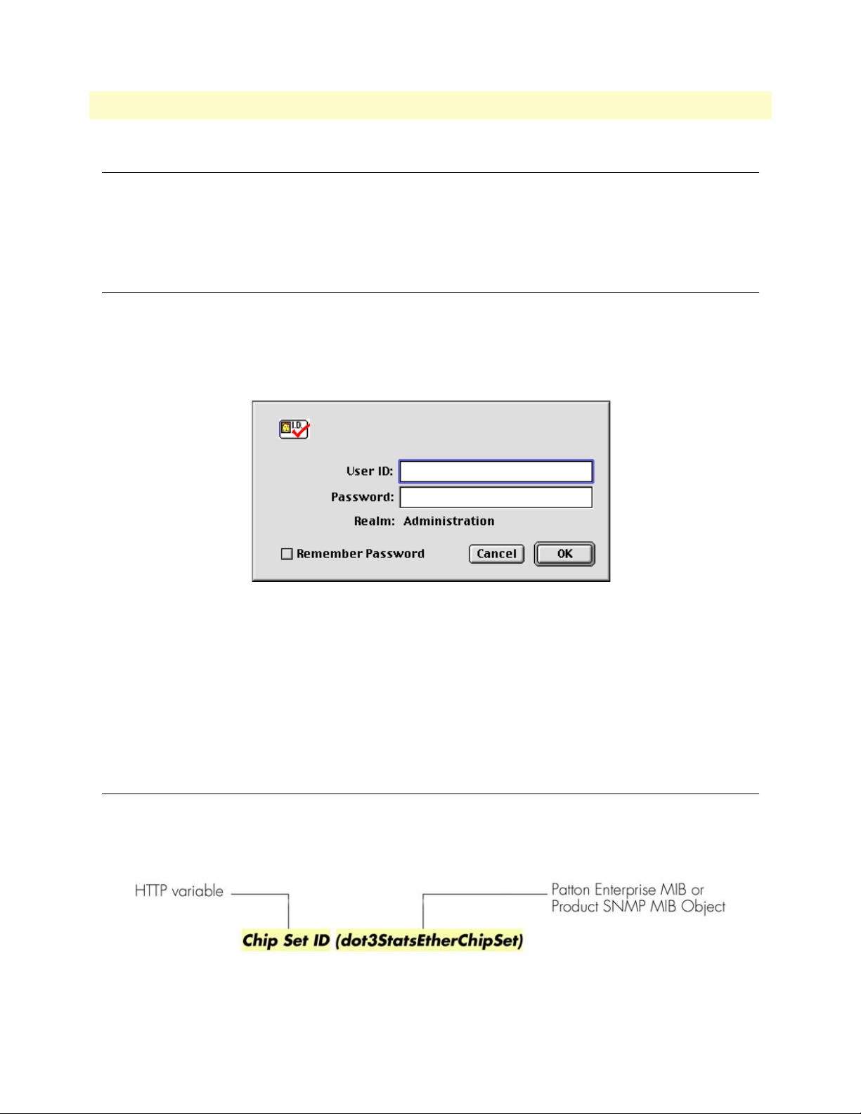
1 • Introduction mDSL DACS Administrators’ Reference Guide
Introduction
You may configure the Digital Access and Cross-Connect System (DACS) by using its internal HTTP/HTML
Administration Pages. However, to enter into the HTTP/HTML pages, you must first define the LAN Address
Technique, LAN IP Address, and LAN Subnet Mask for the DACS. If you have not done so, please refer to the
Getting Started Guide that came with your DACS.
Logging into the HTTP/HTML Administration Pages
To log into the HTTP/HTML Administration pages, you must enter the 4-octet Internet Protocol (IP) (for
example, http://your.server.ip.address) address as the Universal Resource Locator (URL) into a World-Wide Web
(WWW) browser. After you enter the IP address, the DACS will ask for your user name and password as
shown in figure 1.
Figure 1. DACS login window
Your DACS will accept the following default administrative passwords:
• superuser—this password carries full permission to change and view any parameters in the DACS
• monitor—this password allows full viewing of any non-password oriented variables.
Note For security reasons, we recommend that you change these passwords
immediately after initial configuration.
HTTP/HTML and SNMP Object Format
In this document, we shall describe the variables found on each of the internal HTTP/HTML pages. This
description will include brief definitions of the Patton Enterprise MIB or SNMP MIB II object identifiers
wherever applicable. The format of the variables will resemble figure 2.
Figure 2. HTTP/HTML and SNMP object format
20 Introduction
Page 23

mDSL DACS Administrators’ Reference Guide 1 • Introduction
Saving HTTP/HTML Object Changes
Sometimes you will need to save changes that you have made in the HTTP/HTML pages. Do the following to
make changes to read/write variables:
1. Select the appropriate
Modify screen.
2. Make changes to the desired parameter.
3. Click on the
4. Return to the
5. Click on the
Submit Query button.
HOME screen.
Record Current Configuration button.
Note Make sure you follow steps 1 through 5 when modifying the HTTP/
HTML pages. Otherwise, your changes will be lost when the DACS
is power-cycled.
Saving HTTP/HTML Object Changes 21
Page 24

1 • Introduction mDSL DACS Administrators’ Reference Guide
22 Saving HTTP/HTML Object Changes
Page 25

Chapter 2 Home
Chapter contents
Introduction..........................................................................................................................................................24
Operating Status Variables ....................................................................................................................................25
Egress Card Installed (boxEgressType) ............................................................................................................25
Number of Egress Ports (boxEgressCount) .....................................................................................................25
% CPU Idle (boxIdleTime) ............................................................................................................................25
Running Since Last Boot (sysUpTime) ...........................................................................................................25
Total System Alarms (alarmTotal) ..................................................................................................................25
Immediate Actions ................................................................................................................................................26
Record Current Configuration (storeConfig(1)) .............................................................................................26
Hard Reset (hardReset(2)) ..............................................................................................................................26
Set Factory Default Configuration (forceDefaultConfig(3)) ............................................................................26
23
Page 26
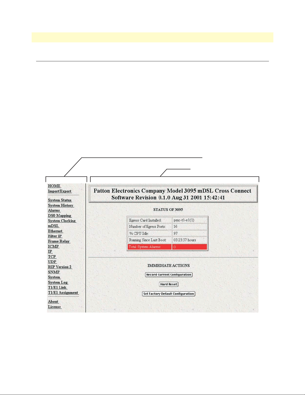
2 • Home mDSL DACS Administrators’ Reference Guide
Introduction
This chapter describes the HOME window—the first Administration Page that you see after logging into the
DACS (see figure 3). From
changes, or reset the system without power-cycling the DACS.
Note Clicking on the HOME link in the Configuration Menu pane will
The
HOME window is divided into two panes: the Configuration Menu pane on the left-hand side and the con-
figuration/information pane (see figure 3). The
subsystems, while the configuration/information pane is where you can view status and other information, or
make changes to the system configuration. Unlike the Configuration Menu pane, which looks the same no
matter which subsystem page you are viewing, the configuration/information pane contents will change as you
move from one subsystem page to another.
HOME, you can monitor current systems status, save any system configuration
return you to the
HOME page from any other page.
Configuration Menu contains the links to the various DACS
Configuration Menu pane
Configuration/information pane
Figure 3. HOME page
24 Introduction
Page 27
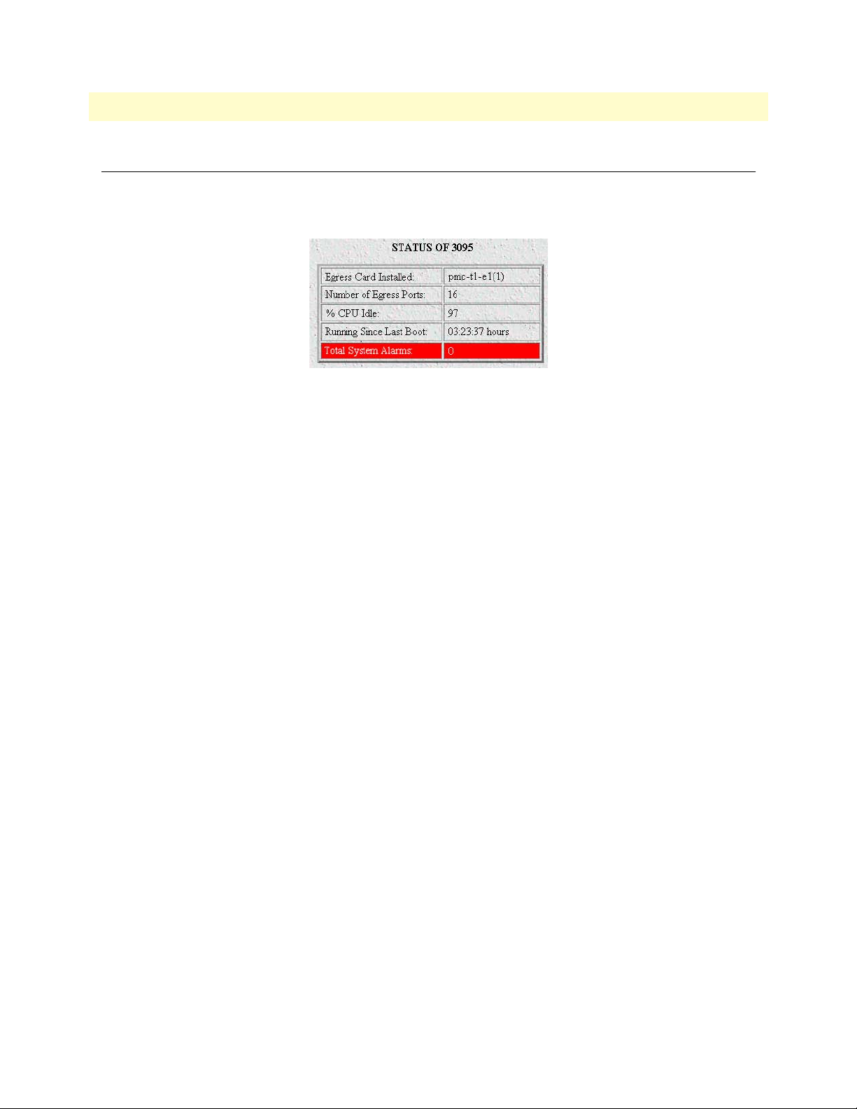
mDSL DACS Administrators’ Reference Guide 2 • Home
Operating Status Variables
There are seven system variables which describe the immediate operating status of the DACS. These variables
are shown in figure 4 and are described in the following sections.
Figure 4. STATUS menu
Egress Card Installed (boxEgressType)
Three parameters define whether an egress card is installed in the 3095 and if so, which one. The parameters
are as follows:
• none(0)—No egress card is installed
• pmc-t1-e1(1)—T1/E1 WAN port card is installed
• pmc-serial(2)—V.35 serial interface card is installed
Number of Egress Ports (boxEgressCount)
Defines the number of ports on the egress card module installed in the system.
% CPU Idle (boxIdleTime)
This is an indication of the amount of system CPU power which is not being utilized by the Model 3095. The
returned value is a percentage of free CPU cycles since the last time the variable was read.
Running Since Last Boot (sysUpTime)
The time (in hundredths of a second) since the DACS was last power-cycled.
Total System Alarms (alarmTotal)
Total number of alarms currently active in the system.
Operating Status Variables 25
Page 28
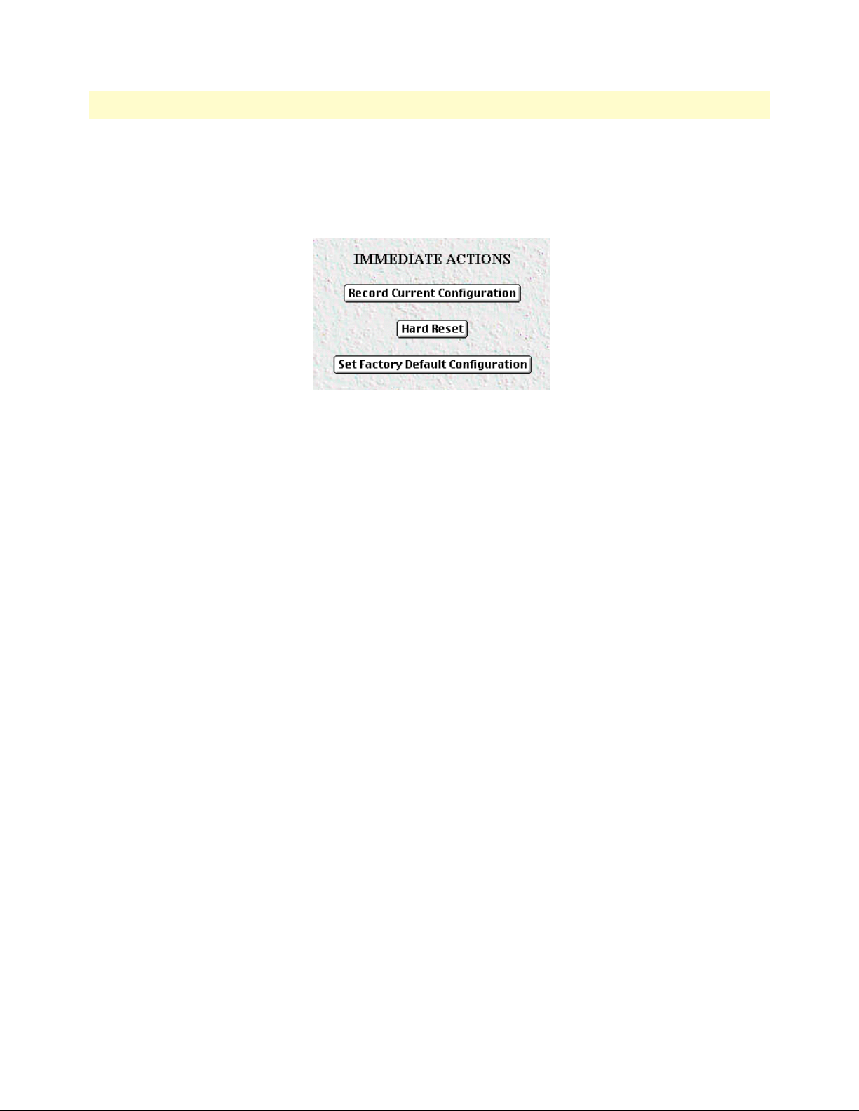
2 • Home mDSL DACS Administrators’ Reference Guide
Immediate Actions
There are several immediate actions (see figure 5) in superuser mode which will cause the DACS to operate
according to the descriptions in the following sections.
Figure 5. Immediate Actions buttons
Record Current Configuration (storeConfig(1))
This feature saves the current configuration in permanent FLASH memory. In other words, configuration
changes made in the subsystem web pages become permanent when you select Record Current Configuration.
1. Configuration changes in the DACS are made in the subsystem web pages by clicking Submit Query.
This stores the configuration in volatile DRAM (Dynamic RAM) only. Since the Submit Query changes
take immediate effect, the administrator can test different configuration parameters without needing to
change the FLASH configuration at this moment.
2. Without clicking on Record Current Configuration, all configuration changes will be lost if the power
is recycled. After doing the Record Current Configuration save, the current configuration of the DACS
will not be lost with power cycling.
Note The most important step after completing the configuration is to save it in
permanent memory by clicking on Record Current Configuration.
Hard Reset (hardReset(2))
This button causes the DACS to perform a cold restart. When you select Hard Reset, the DACS requests
confirmation for the execution of this command. Then, the DACS will disconnect all current sessions, re-initialize the interfaces, and re-load configuration parameters from FLASH.
Set Factory Default Configuration (forceDefaultConfig(3))
This button clears out the configuration in FLASH and loads the factory default parameters into FLASH
memory. The factory default settings will not execute on the DACS until it is re-booted, for example by doing
a Hard Reset.
Note Set Factory Default Configuration will delete the DACS’s Ether-
net IP address and any other site specific settings made for your particular installation. You will have to re-enter the DACS’s Ethernet IP
address and netmask using the front panel control port in order to use
the HTTP/HTML Management pages.
26 Immediate Actions
Page 29

Chapter 3 Import/Export
Chapter contents
Introduction..........................................................................................................................................................28
Export Configuration ............................................................................................................................................28
Import Configuration............................................................................................................................................30
27
Page 30
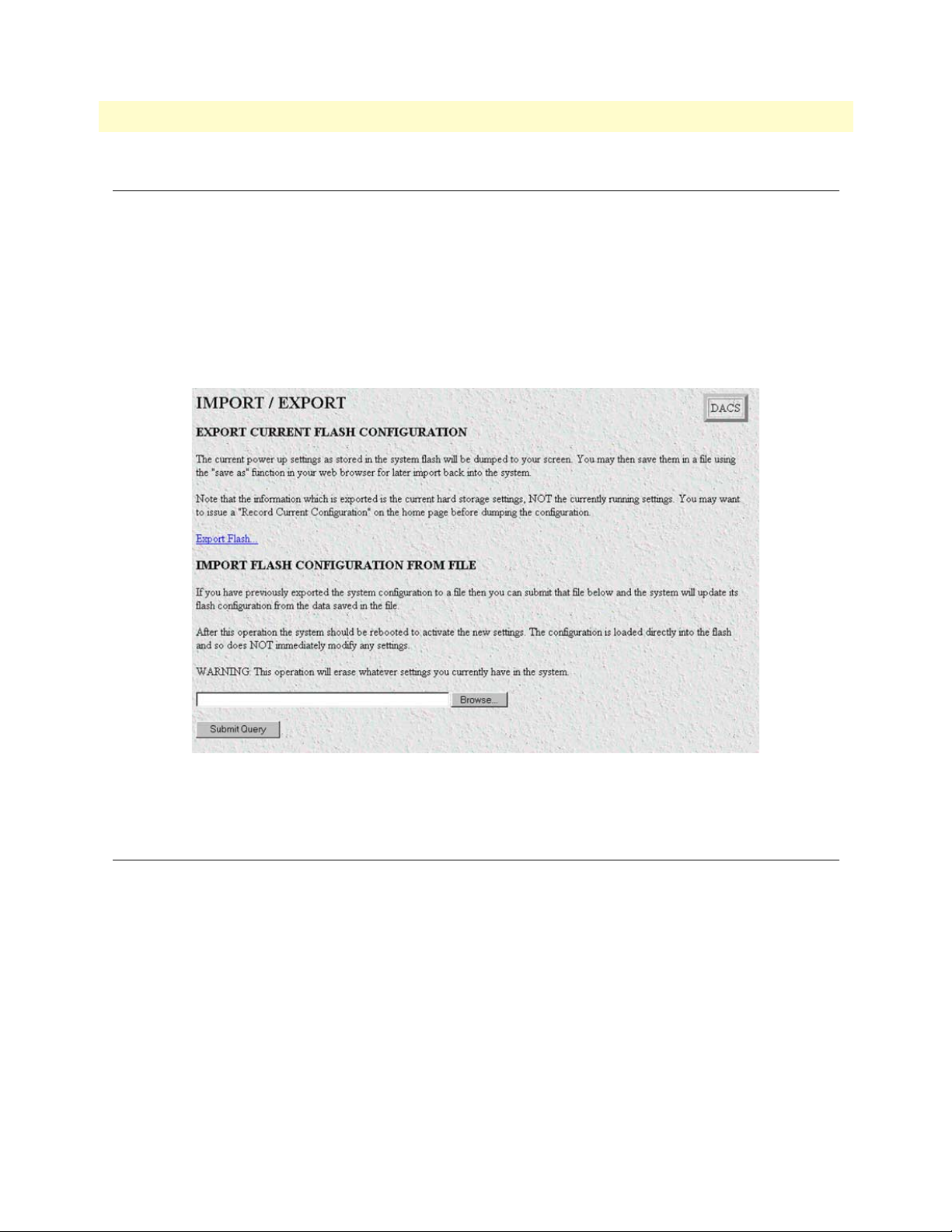
3 • Import/Export mDSL DACS Administrators’ Reference Guide
Introduction
The Import/Export function enables you to make a backup (or export) copy of your DACS’s configuration
parameters. By exporting the configurations, the saved files can quickly be loaded, or imported, into a replacement DACS—greatly speeding up the installation process should an DACS need replacing.
Note All actions for Import/Export require superuser access privileges.
To import or export a configuration, click on
Import/Export main window (see figure 6).
Import/Export under the Configuration Menu to display the
Figure 6. Import/Export main window
Export Configuration
Note The exported configuration file is a text-format file. Do not try, how-
ever to edit the operating characteristics contained in the file.
Note The parameters that will be exported are the power-up settings as they
are stored in flash memory and may not be the current operating
parameters. To ensure that you export the most current parameters,
go to
HOME, then click on the Record Current Configuration button
under
Immediate Actions.
28 Introduction
Page 31

mDSL DACS Administrators’ Reference Guide 3 • Import/Export
To export the flash configuration, click on the Export Flash link on the Import/Export main page. The DACS
will display text configuration information resembling that shown in figure 7.
Figure 7. Typical DACS flash memory configuration data
Export Configuration 29
Page 32

3 • Import/Export mDSL DACS Administrators’ Reference Guide
To save the displayed data as a text file, select the Save option on your browser (see figure 8). For example,
under Netscape, select
parameters to a text file. Select the location where you want the file stored, type a file name, and click
File > Save As. A dialog box will display enabling you to save the contents of the export
Save.
Figure 8. Saving the DACS flash memory configuration data as a text file
Import Configuration
To import a configuration file into the DACS, type the complete path and filename for the configuration file
you wish to load or click on the
ton (see figure 6 on page 28).
Upon successfully importing the file, the DACS will display Configuration Load Complete, indicating that the
new operating parameters have been loaded into flash memory.
Click on
HOME under the Configuration Menu, then click on the Hard Reset button under Immediate Actions.
Note Do not select Record Current Configuration after importing configu-
Browse… button to select the desired file, then click on the Submit Query but-
ration parameters because the configuration is imported directly into
non-volatile FLASH memory. Upon doing a Hard Reset the
imported configuration is now the operational software is RAM.
30 Import Configuration
Page 33

Chapter 4 System Status
Chapter contents
Introduction..........................................................................................................................................................32
Refresh Rate ..........................................................................................................................................................32
System Status parameters.......................................................................................................................................33
Navigating the WAN Port Information parameters .........................................................................................33
Navigating the mDSL Port Information parameters ........................................................................................34
31
Page 34
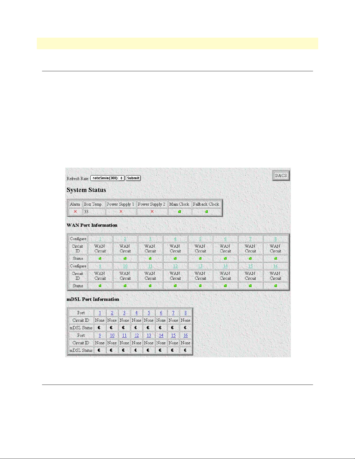
4 • System Status mDSL DACS Administrators’ Reference Guide
Introduction
The System Status window (see figure 9) displays a comprehensive status summary of the major Model 3095
subsystems. The web page is divided into the following parameter groupings:
• System Status—Displays the state of Alarms, the internal temperature of the 3095, the current operational
status of the two power supplies and the 3095’s system clock.
• WAN Port Information—Displays the circuit name (Circuit ID), and operational state (Status) of each
WAN circuit. Clicking on the Configure link located above each WAN Circuit, displays the DACS WAN
Circuit CONFIGURATION LINK window for that WAN port.
• mDSL Port Information—Displays the name (Circuit ID) and operational state (mDSL Status) of each
mDSL port. Clicking on the
Page window for that mDSL port.
Port link located above each Circuit ID, displays the mDSL Port Information
Figure 9. System Status window
Refresh Rate
This parameter selects how often the System Status page is refreshed. The user-selectable options are:
• none(0)
• rate10sec(10)—Refresh every 10 seconds
32 Introduction
Page 35

mDSL DACS Administrators’ Reference Guide 4 • System Status
• rate15sec(15)—Refresh every 15 seconds
• rate30sec(30)—Refresh every 30 seconds
• rate1min(60)—Refresh every minute (60 seconds)
• rate2min(120)—Refresh every 2 minutes (120 seconds)
• rate3min(180)—Refresh every 3 minutes (180 seconds)
• rate5min(300)—Refresh every 5 minutes (300 seconds)
Click Submit Query after selecting the desired refresh rate.
System Status parameters
The system status table displays the following parameters:
• Alarm—If the Alarm is flashing red, there is an alarm condition in the box. For further information on the
alarm, review the alarms in the other tables on this web page or refer to Chapter 6, “Alarms” on page 39.
• Box Temp.—Displays the internal temperature in degrees Centigrade.
• Power Supply 1
• Power Supply 2
• Main Clock
• Fallback Clock.
The Box Temp. reading is displayed in degrees Centigrade. The status of the remaining parameters is shown by
one of the following symbols:
• Green square: No alarms are present and functioning properly.
• Red flashing star: An alarm or alarms are present.
If there is a flashing red indicator, go to the appropriate chapter listed in Table 3.
Table 3. System status/subsystem reference
System status Subsystem
Alarm Chapter 6, “Alarms” on page 39
Box Temp. Chapter 6, “Alarms” on page 39
Power Supply S1
Power Supply S2
Main Clock
Fallback Clock
Chapter 6, “Alarms” on page 39
Chapter 6, “Alarms” on page 39 and Chapter
8, “System Clocking” on page 55
Navigating the WAN Port Information parameters
The following WAN circuit categories are available:
• Configure—Clicking one of these links displays a WAN Circuit Configuration Link window for configur-
ing a WAN port.
• Circuit ID—This is the name given to the WAN circuit.
System Status parameters 33
Page 36

4 • System Status mDSL DACS Administrators’ Reference Guide
• Status—Shows the condition of the WAN circuit.
The WAN Port status color indicators show the state of each mDSL port.The different symbols are defined as
follows.
• Green square: Functioning properly and no alarms are present.
• Flashing red star: An alarm or alarms are present.
• Yellow triangle: A yellow alarm is present.
• Blue square: The circuit is in a loopback condition.
• Gray circle: Unused, not activated.
For full details on the WAN circuit parameters, refer to Chapter 21, “T1/E1 Link” on page 157.
Navigating the mDSL Port Information parameters
For the mDSL modem ports, there are three categories of information: Port, Circuit ID, and mDSL Status.
The hyperlink for each individual Port displays the mDSL Port Information Page. The Circuit ID is the name
of each mDSL modem port. The mDSL Status color indicators show the state of each mDSL port.The different symbols are defined as follows.
• Green square: Functioning properly and no alarms are present.
• Flashing red star: An alarm or alarms are present.
• Blue square: The circuit is in a loopback condition.
• Gray circle: Unused, not activated.
For full details on the mDSL circuit parameter, consult Chapter 9, “mDSL Port Configuration” on page 59.
34 System Status parameters
Page 37

Chapter 5 System History
Chapter contents
Introduction..........................................................................................................................................................36
WAN Port Information table ................................................................................................................................36
mDSL History table ..............................................................................................................................................37
35
Page 38

5 • System History mDSL DACS Administrators’ Reference Guide
Introduction
The System History window (see figure 10) provides quick access to the configuration parameters and statistical data for all WAN circuits and mDSL ports. It contains the following tables:
WAN Port Information—Displays configuration hyperlinks, the name for each WAN port and hyperlinks to
•
the statistical history, both near and far end, of the WAN ports.
mDSL History—Displays port configuration hyperlinks, the name of each mDSL circuit, and hyperlinks to
•
each ports statistical history
Figure 10. System History window
WAN Port Information table
The WAN Port Information table contains the following information:
• Configure—Clicking on this link displays the WAN Circuit Configuration Link window for configuring or
reviewing the configuration.
• Circuit ID—This is the name of a WAN circuit
• Near End History—These rows have
of Near End Performance window
• Far End History—These rows have Near End and Far End hyperlinks to the statistical data at the History of
Far End Performance window.
For detailed information on the WAN port parameters, refer to Chapter 21, “T1/E1 Link” on page 157.
36 Introduction
Near End and Far End hyperlinks to the statistical data at the History
Page 39

mDSL DACS Administrators’ Reference Guide 5 • System History
mDSL History table
The mDSL table contains the following information:
• Port—Clicking on this link displays the mDSL Port Information Page window for reviewing or configuring
the mDSL port.
• Circuit ID—This is the name of an mDSL circuit
• History—Clicking on this link displays the mDSL circuits’ individual History of Near End Performance:
mDSL Port window.
For more information on the mDSL port parameters, refer to Chapter 9, “mDSL Port Configuration” on page
59.
mDSL History table 37
Page 40

5 • System History mDSL DACS Administrators’ Reference Guide
38 mDSL History table
Page 41

Chapter 6 Alarms
Chapter contents
Introduction..........................................................................................................................................................40
Displaying the alarms window...............................................................................................................................40
Alarm Response Outputs ................................................................................................................................42
Relay Response (alarmRlay(1)) ..................................................................................................................42
Minor Alarm SYSLOG Priority (minorSyslogPriority) ..............................................................................42
Major Alarm SYSLOG Priority (majorSyslogPriority) ...............................................................................42
Minor Alarm SNMP Trap IP [address] (minorTrapIp) .............................................................................42
Major Alarm SNMP Trap IP [address] (majorTrapIp) ..............................................................................42
Temperature Threshold (boxAlarmTemperature) ......................................................................................42
Current Box Temperature (boxTemperature) ............................................................................................42
Clear All Alarms ........................................................................................................................................42
Alarms ............................................................................................................................................................42
Alarm ID (alarmDefIndex) ........................................................................................................................42
Alarm Name (alarmName) ........................................................................................................................43
Alarm Severity (alarmSeverity) ..................................................................................................................43
Alarm Time (alarmTicks) ..........................................................................................................................43
Alarm Count (alarmCount) .......................................................................................................................43
Generate Alarm (alarmGenerate(1) ...........................................................................................................43
Clear Alarm (alarmGenerate(2) .................................................................................................................43
Alarm Parameters ............................................................................................................................................44
Types of Alarms ..............................................................................................................................................44
Modify Response—Configuring the alarm response system...................................................................................45
Relay Response (alarmRelay(1)) ......................................................................................................................45
Minor Alarm Syslog Priority (minorSyslogPriority) & Major Alarm Syslog Priority (majorSyslogPriority) .....45
Minor Alarm SNMP Trap IP [address] (minSyslogPriority) ...........................................................................45
Major Alarm SNMP Trap IP [address] (majorSyslogPriority) .........................................................................45
Temperature Threshold (boxAlarmTemperature) ...........................................................................................45
Modify Alarms—Configuring alarm severity levels ................................................................................................46
39
Page 42

6 • Alarms mDSL DACS Administrators’ Reference Guide
Introduction
The DACS has an extensive alarm reporting system which enables users to configure, monitor, and test major
and minor alarms. The alarm system can be set to notify of equipment failures (for example, a power supply
failure) or T1/E1 port malfunctions. The alarms that can be configured by the system administrator to generate
alerts based on the condition of the DACS.
Displaying the alarms window
Click on Alarms under the Configuration Menu to display the Alarm System main window (figure 11).
Note The system administrator can manually generate a specific alarm for
testing purposes or clear the alarm counters from the main window.
Figure 11. Alarms main window
40 Introduction
Page 43

mDSL DACS Administrators’ Reference Guide 6 • Alarms
The mDSL Multiplexer has four methods to notify an alarm condition:
1. Front panel LED—The front panel ALARM LED has three states that indicate the presence and severity
of an alarm. The states are:
- Off—No alarm present
- Solid—Minor alarm
- Flashing—Major alarm.
Note The POWER LED will flash if a power supply failure alarm is
present. If both power supplies are functioning normally, the LED
will be lit constantly. Otherwise, the LED will flash.
2. Administration web page indication—The Alarms window of the administration page uses red highlighting to indicate which items are in an alarm state (see figure 12).
Figure 12. Sample alarm indication
3. SYSLOG/SNMP—For external notification, the DACS can be configured to send a SYSLOG message or
an SNMP TRAP to an external management host. To configure the alarm response for either SNMP Traps
or SYSLOG messages, click on the
Alarm Response link (go to “Alarm Parameters” on page 44).
4. Alarm Relay—Located on the rear of the chassis, the Alarm Relay is a 3-position terminal block. The
Alarm Relay may be configured to indicate when a major alarm, a minor alarm or both major and minor
alarms occur. It may also be disabled. The 3-position terminal block numbers its pins from 1 to 3 from left
to right. When no alarms are indicated, pins 1 and 2 are normally closed and pins 2 and 3 are normally
open. Upon the occurrence of an alarm—the type is configured as major, minor, or both—pins 1 and 2 are
open and pins 2 and 3 are closed.
Besides enabling a user to view current alarm status, you may manually generate an alarm as a test and clear the
alarm time and count variables. The Alarms main window also contains links to the following:
• Modify Response—for configuring how the Alarm Response Outputs notify administrators of an alarm (see
“Alarm Parameters” on page 44)
• Modify Alarms—Clicking on this link takes you to a window where you can configure the importance or
severity of each individual alarm. The severity of the alarm type may generate a minor, major, minor self-
Displaying the alarms window 41
Page 44

6 • Alarms mDSL DACS Administrators’ Reference Guide
clearing, or major self-clearing alarm. Any alarm type may be disabled. (“Modify Alarms—Configuring
alarm severity levels” on page 46)
Alarm Response Outputs
Alarm Response Outputs display the current setting for handling alarm notification via the different Alarm
Response Outputs. To change the Alarm Response Outputs parameters, refer to “Alarm Parameters” on
page 44.
Relay Response (alarmRlay(1))
The relay of the Alarm Port on the rear of the chassis will be activated when a major, minor, or both major and
minor alarm is generated. The Alarm Port may also be disabled.
Minor Alarm SYSLOG Priority (minorSyslogPriority)
Sets the priority of the minor alarm SYSLOG message that will be generated upon the occurrence of a minor
alarm.
Major Alarm SYSLOG Priority (majorSyslogPriority)
Sets the priority of the major alarm SYSLOG message that will be generated upon the occurrence of a major
alarm.
Minor Alarm SNMP Trap IP [address] (minorTrapIp)
Displays the IP address of a SNMP management station for receiving the SNMP trap messages upon the
occurrence of an active minor alarm. The SNMP trap messages are sent in UDP datagrams. When the IP
address is set to 0.0.0.0, no trap messages will ever be sent.
Major Alarm SNMP Trap IP [address] (majorTrapIp)
The same function as the Minor Alarm Trap IP except for only the occurrence of active major alarms.
Temperature Threshold (boxAlarmTemperature)
An alarm will be generated when the box temperature exceeds this temperature value in degrees Celsius.
Current Box Temperature (boxTemperature)
The internal temperature in the box in degrees Celsius.
Clear All Alarms
Click on this button to clear all the alarms (that is, to reset all the alarms). This clearing action will, for all the
alarms, reset the alarm, reset Time Since Alarm to 0.00 seconds, and reset the Alarm Count to 0 (zero).
Alarms
This portion of the Alarms main window displays the alarm status table, where you can view current alarm status, manually generate an alarm as a test, and clear the alarm time and alarm count variables.
Alarm ID (alarmDefIndex)
This identifies the alarm item by a numerical index.
42 Displaying the alarms window
Page 45

mDSL DACS Administrators’ Reference Guide 6 • Alarms
Alarm Name (alarmName)
The alarm items are grouped into two categories: system and WAN trunk alarms. The system group category
lists DACS temperature and power supply status. The WAN category monitors the T1/E1 ports for yellow and
red alarms.
Alarm Severity (alarmSeverity)
Used for selecting the type of alarm that is generated by a particular event. The four types are:
• Minor
• Major
• Minor self-clearing
• Major self-clearing
The setting can also be disabled (set to ignore an alarm)
Alarm Time (alarmTicks)
The Alarm Time column displays the number of seconds the alarm has been activated.
Alarm Count (alarmCount)
The Alarm Count column indicates how many times the alarm has occurred and is useful for monitoring selfclearing alarms.
Generate Alarm (alarmGenerate(1)
For testing purposes, clicking the Generate Alarm button next to each alarm name will cause that alarm condition to be activated.
Clear Alarm (alarmGenerate(2)
Clicking the Clear Alarm button resets the alarm to a non-alarm condition.
Displaying the alarms window 43
Page 46

6 • Alarms mDSL DACS Administrators’ Reference Guide
Figure 13. Alarm Response System window
Alarm Parameters
The Alarm Status Table on the Alarm System main page displays the current alarm status. You may also manually generate an alarm as a test and clear the alarm, the alarm time and the alarm count variables.
• Alarm ID—The Alarm ID identifies the alarm numerically. (For example, Alarm ID #2 identifies the alarm
named “Box: Power Supply I Failed.” )
• Alarm Name—The alarm items are grouped into three categories: Box, WAN, and mDSL alarms. The Box
alarm group contains the alarms “Over Temperature” and “Power Supply Fail” for each of the two power
supplies. The WAN alarm group includes yellow and red alarms. The mDSL alarm group has Line Down,
Bit Error, and Hardware Failure alarms for each mDSL modem link.
• Alarm Severity—For each alarm, it shows whether the alarm is disabled or configured to generate a major,
minor, major self-clearing, or minor self-clearing alarm.
• Time Since Alarm—Elapsed time since the alarm occurred (in seconds).
• Alarm Count—The number of times this alarm has occurred since it has been cleared. It is also for moni-
toring self-clearing alarms.
• Generate Alarm—For testing a particular alarm, click on Generate Alarm. This activates the alarm as if the
actual trigger event had occurred.
• Clear Alarm—Clearing the alarm resets the alarm, resets Time Since Alarm to 0.00 seconds and resets
Alarm Count to 0 (zero).
Types of Alarms
• Box Alarm Group
- Box: Over Temperature—When the internal box temperature exceeds the temperature threshold under
Modify Response…, an alarm will be generated.
- Box: Power Supply I–II Fail—An alarm will be generated if a power supply fails or if the power source for
the supply fails or is disconnected.
• WAN Alarm Group
- WAN 1–16: Yellow Alarm—When a WAN port sees a yellow alarm, the specific WAN alarm will be sent.
44 Displaying the alarms window
Page 47

mDSL DACS Administrators’ Reference Guide 6 • Alarms
- WAN 1–16: Red Alarm—When a WAN port sends a red alarm, the specific WAN alarm will be sent.
• mDSL Alarm Group
- mDSL 1–16: Line Down—When an mDSL modem line is down, an alarm is generated.
- mDSL 1–16: Bit Error—When the bit error for an mDSL modem connection exceeds a particular value,
an alarm is generated.
- mDSL 1–16: Hardware Failure—When an internal mDSL modem has a hardware failure, an alarm is
generated.
Modify Response—Configuring the alarm response system
The alarm response outputs refer to points of external notification. Note that the front panel Alarm LED and
the web administration pages will always indicate an occurrence of an active alarm. To configure each alarm
response output, click on
the alarm response output that you want to configure with the pull down menu. After configuring a specific
alarm response output, remember to click on Submit Query before going to the next alarm response output;
otherwise the change will not occur.
Relay Response (alarmRelay(1))
The relay may be set to go active for minor alarms, major alarms, or both. It may also be disabled with the
parameter “none.”
Modify Response. The Alarm Response System page appears (see figure 13). Choose
Minor Alarm Syslog Priority (minorSyslogPriority) & Major Alarm Syslog Priority
(majorSyslogPriority)
When a minor/major alarm occurs, a message of the selected priority is sent to the Syslog engine. The Priority
levels are priorityDisable(100), prioritySystem(80), priorityService(60), priorityOddity(40), priorityInfo(20),
priorityDebug(10), and priorityVerbose(5). For more information on Syslog messages, refer to Chapter 20,
“System Log”.
Minor Alarm SNMP Trap IP [address] (minSyslogPriority)
Upon the occurrence of a minor alarm, an SNMP Trap message is sent to a host system (or a management station). This parameter is the IP address of the host running the SNMP Trap daemon. When the IP address is set
to 0.0.0.0 no SNMP Trap message will be sent.
Major Alarm SNMP Trap IP [address] (majorSyslogPriority)
This parameter functions in the same manner as the Minor Alarm SNMP Trap IP [address] except it applies to
major alarms. Upon the occurrence of a major alarm, an SNMP Trap message is sent to a host system (or a
management station). This parameter is the IP address of the host running the SNMP Trap daemon. When the
IP address is set to 0.0.0.0 no SNMP Trap message will be sent.
Temperature Threshold (boxAlarmTemperature)
An alarm message is generated when the internal box temperature exceeds this threshold value (degrees Celsius). You can change the threshold temperature, but we recommend that you use the factory default.
Modify Response—Configuring the alarm response system 45
Page 48

6 • Alarms mDSL DACS Administrators’ Reference Guide
Modify Alarms—Configuring alarm severity levels
Clicking on Modify Alarms window (see figure 14) displays a table listing each individual alarm. From this
page you can configure the severity for each alarm (such as major, minor, major self-clearing, and minor selfclearing). Each alarm can be disabled as appropriate for your application.
Figure 14. Modify Alarms settings window
The alarms can be independently configured to generate alarm messages. Each alarm item can be set for one of
the following severity levels:
• Ignore(0)—Do not generate an alarm.
• Minor(1)—Generate a minor alarm that will not reset until the administrator manually clears it.
• Major(2)—Generate a major alarm that will not reset until the administrator manually clears it.
• MinorSelfClearing(3)—Generate a minor alarm that automatically clears after 30 seconds. If the alarm con-
dition has not ceased, the alarm will be automatically cleared, but another alarm will be immediately gener-
46 Modify Alarms—Configuring alarm severity levels
Page 49

mDSL DACS Administrators’ Reference Guide 6 • Alarms
ated. If the alarm condition has ceased, the alarm will be automatically cleared after the same fixed period of
time.
• MajorSelfClearing(4)—Same as MinorSelfClearing(3) except that it is a Major alarm instead of Minor.
Note For maximum application flexibility, the administrator shall choose
which constitute major or minor alarm. Some examples of typical
major and minor alarms include:
- Box: Over Temperature—Major Alarm
- mDSL 10: Bit Error—Minor Alarm
- WAN 1: Red Alarm—MajorSelfClearing
- WAN 1: Yellow Alarm—MinorSelfClearing
To set an alarm, click on the drop-down menu for the desired alarm item, choose the new setting followed by
clicking on Submit Query.
Modify Alarms—Configuring alarm severity levels 47
Page 50

6 • Alarms mDSL DACS Administrators’ Reference Guide
48 Modify Alarms—Configuring alarm severity levels
Page 51

Chapter 7 DS0 Mapping
Chapter contents
Introduction..........................................................................................................................................................50
Displaying the DS0 Mapping window...................................................................................................................50
DACS Display Type .......................................................................................................................................50
Help (DACS help information) ......................................................................................................................51
Static Connection ...........................................................................................................................................51
ID (daxConnectionID) .............................................................................................................................51
Device Type (daxDeviceTypeTomDSL) (daxDeviceTypeFrommDSL) .....................................................51
Device Number (daxDeviceNumberTomDSL) (daxDeviceNumberFrommDSL) .....................................51
Device Slots (daxDeviceSlotTo) (daxDeviceSlotFrom) ..............................................................................52
Configuration .................................................................................................................................................52
49
Page 52

7 • DS0 Mapping mDSL DACS Administrators’ Reference Guide
Introduction
One of the remote locations is the CPE’s mDSL modem. The second remote location is typically connected
through some WAN port’s time slots. For communication between these remote locations they shall be connected together within the DACS. These connections are configured in the DS0 mapping window.
The following types of internal connections are available:
• Between an mDSL modem and time slots in a WAN port
• Between two mDSL modems
• Between time slots within the same or between different WAN ports
Note When the text in this document refers to a 16-modem DSL, the ref-
erence applies equally to the 8-modem mDSL version as well.
Displaying the DS0 Mapping window
Do the following:
1. Click on
DS0 Mapping under the Configuration Menu. The DS0 Mapping Configuration window dis-
plays (see figure 15).
Figure 15. DS0 Mapping Configuration window
The following sections describe the contents of the DS0 Mapping Configuration window.
DACS Display Type
You can configure or map the static connections by using the Long Format or the Command Line Format.
• displayLongForm(0)—This is the easiest to use by selecting the options from the pull-down menus.
• displayCliForm(1)—If you prefer the command line format, select displayCliForm(1) and click on the Sub-
mit Query button. Consult the following sections for the format of the command line.
50 Introduction
Page 53

mDSL DACS Administrators’ Reference Guide 7 • DS0 Mapping
Help (DACS help information)
Clicking on the Help button displays the DACS Help Information window (see figure 16). The purpose of
this window is to help the user learn how to add DS0 connections using the DACS HTML pages. This window define all of the parameters available within this web page. If you are using the Command Line Format to
make connections, scroll down the window to the heading
Command Line Format. The information contained
in the Help window is also covered in this chapter.
Figure 16. Example DACS Help Information window
Static Connection
Pull Down Menus
Each pull down window signifies part of a connection. Each connection is made up of an "A" side and a "B"
side. These names have been arbitrarily chosen and do not signify the direction that data will travel. All data
will be bi-directional. There are three parameters that need to be defined for each connection, they are:
• Device Type
• Device Number
• Device Slots
ID (daxConnectionID)
Then ID number identifies each mapping with a unique number. The number is automatically assigned
sequentially when a static connection is entered. The ID number begins at “1.”
Device Type (daxDeviceTypeTomDSL) (daxDeviceTypeFrommDSL)
The Device Type specifies the physical interface that you will be connecting. Within the 3095 the user has the
option of selecting either a T1/E1 WAN line or an mDSL modem. While the one side may be a T1/E1 WAN
line and the other an mDSL modem, note that both sides of the connection can be T1/E1 or both sides can be
mDSL. The two Device Types are t1-e1(1) and mDSL(3).
Device Number (daxDeviceNumberTomDSL) (daxDeviceNumberFrommDSL)
The next step in creating a connection through the DACs is to select the port that you would like to use. This
corresponds to the Port Number for the devices selected in the previous step. For example, if you would like to
make a connection to mDSL Port 3 (referring to mDSL modem #3), then select "Port 3" in the "Device Number" field. Note that there are 16 t1-e1 ports. Since there are either 8 or 16 mDSL modems within the 3095,
you may choose any of the 8 or 16 ports.
Displaying the DS0 Mapping window 51
Page 54

7 • DS0 Mapping mDSL DACS Administrators’ Reference Guide
Device Slots (daxDeviceSlotTo) (daxDeviceSlotFrom)
The “slots” input identifies the DS0 channels—each DS0 channel is 64 kbps—that you would like to connect.
Each mDSL modem has up to 31 DS0 channels. Each time slot in a T1 or E1 WAN port has 24 or 31 DS0
channels, respectively. When selecting the slots you must select the same number of slots on the “A” and “B”
side of the connection. The slots are selected by entering a string that represents the slots. For the mDSL ports,
slots 1–31 are available. For a WAN port configured as a T1, the available slots are numbered from 1–24. For a
WAN port configured as an E1, the available slots are 1–31. The following notation should be used for entering the slots. Several examples are given below.
• dash: (-) 1 - 4
• comma: (,) 1,4,9
• combo: 1 - 2, 3,6 - 7
For example, to connect a T1 Port using timeslots 1,2, 5, 6, 7, and 15, you can input any of the following
strings:
1,2, 5-7, 15
1 - 2, 5,6,7,15
1 - 2, 5 - 6, 7, 15
Note Only contiguous timeslots beginning at 1 are available in the mDSL
modems.
Configuration
The user can make connections in the box using two different methods. The easiest way is by using the pull
down windows provided. But the user can also add connection using the command line format by entering a
text string. To input a static connection into the box using the text string. Use the following convention:
• DeviceA:PortA:SlotsA/DeviceB:PortB:SlotsB
Device Options - The interface that you would like to select
1) t1-e1
2) mDSL
Port Options - The Port Number (starting at 1) may be one of the 16 WAN ports or one of the 16 mDSL
modems. To configure Slots (DS0 channels), choose the slots that you would like to use. The following
notations are allowed:
1) dash (-): 1 - 4
2) comma (,): 1,4,9
3) combination of dashes and commas: 1 - 2, 3,6 - 7
Example #1: To connect a T1 line, (WAN) Port 1, timeslots 1–24 to an mDSL modem, Port 3 (modem
#3), timeslots 1,2, input the following string:
t1-e1:1:1 - 24/mDSL:3:1 – 24
52 Displaying the DS0 Mapping window
Page 55

mDSL DACS Administrators’ Reference Guide 7 • DS0 Mapping
Example #2: To connect a T1 line, (WAN) Port 2, timeslots 4 – 6, to another T1 line, (WAN) Port 3,
timeslots 8 – 10, input the following string:
t1-e1:2:4 – 6/t1-e1:3:8-10
Example #3: To connect two mDSL modems together, such as mDSL modem #6, timeslots 1 – 16, to
mDSL modem #20, timeslots 1 – 16, input the following string:
mDSL:6:1-16/mDSL:20:1-16
Click Sumbit Query to save the static connection in volatile memory.
Displaying the DS0 Mapping window 53
Page 56

7 • DS0 Mapping mDSL DACS Administrators’ Reference Guide
54 Displaying the DS0 Mapping window
Page 57

Chapter 8 System Clocking
Chapter contents
Introduction..........................................................................................................................................................56
Configuring the System Clock Settings..................................................................................................................56
Main Reference (daxClockMainRef) ...............................................................................................................56
Fallback Reference (daxClockFallbackRef) ......................................................................................................57
Clock Status (daxClockFailure) .......................................................................................................................58
55
Page 58

8 • System Clocking mDSL DACS Administrators’ Reference Guide
Introduction
Click on Clocking in the Configuration Menu to display the System Clocking Configuration main window
(see figure 17).
Figure 17. System Clocking Configuration window
The Clocking window is where the primary and secondary clocking sources that synchronize all DS0 channels
are configured. The DACS uses a single clock source for all DS0 channels. You select the clock for the DS0
channels from the following clock sources:
• An internal oscillator
• Any of the WAN ports
• Any of the mDSL remote modems
• An external clock (accessed via the Ext. Clock 3-position terminal block located on the rear panel of the
DACS.”
Main Reference setting determines the clock source if this source is operational. If the Main Reference
The
clock source fails, the
Fallback Reference becomes the clock source to synchronize all DS0 channels. The
clock source is the system clock for the entire DACS.
Configuring the System Clock Settings
The following sections describe configuring the clock settings.
Main Reference (daxClockMainRef)
The Main Reference and Fallback Reference parameters have the same selections for system clock. Make sure
you choose different clock sources for the Main Reference and Fallback Reference. The following settings
are available:
• none(0)—No clock selection.
• wan-1(1)—WAN port #1 is the clock source
• wan-2(2)—WAN port #2 is the clock source
• wan-3(3)—WAN port #3 is the clock source
• wan-4(4)—WAN port #4 is the clock source
• wan-5(5)—WAN port #5 is the clock source
• wan-6(6)—WAN port #6 is the clock source
• wan-7(7)—WAN port #7 is the clock source
56 Introduction
Page 59

mDSL DACS Administrators’ Reference Guide 8 • System Clocking
• wan-8(8)—WAN port #8 is the clock source
• wan-9(9)—WAN port #9 is the clock source
• wan-10(10)—WAN port #10 is the clock source
• wan-11(11)—WAN port #11 is the clock source
• wan-12(12)—WAN port #12 is the clock source
• wan-13(13)—WAN port #13 is the clock source
• wan-14(14)—WAN port #14 is the clock source
• wan-15(15)—WAN port #15 is the clock source
• wan-16(16)—WAN port #16 is the clock source
• mdsl-1(51)—mDSL port #1 is the clock source
• mdsl-2(52)—mDSL port #2 is the clock source
• mdsl-3(53)—mDSL port #3 is the clock source
• mdsl-4(54)—mDSL port #4 is the clock source
• mdsl-5(55)—mDSL port #5 is the clock source
• mdsl-6(56)—mDSL port #6 is the clock source
• mdsl-7(57)—mDSL port #7 is the clock source
• mdsl-8(58)—mDSL port #8 is the clock source
• mdsl-9(59)—mDSL port #9 is the clock source
• mdsl-10(60)—mDSL port #10 is the clock source
• mdsl-11(61)—mDSL port #11 is the clock source
• mdsl-12(62)—mDSL port #12 is the clock source
• mdsl-13(63)—mDSL port #13 is the clock source
• mdsl-14(64)—mDSL port #14 is the clock source
• mdsl-15(65)—mDSL port #15 is the clock source
• mdsl-16(66)—mDSL port #16 is the clock source
• internal(200)— The internal free-running oscillator is the clock source.
• external(300)—The external clock source connected to the 3-position terminal block on the rear of the
Model 3095 is the clock source.
Fallback Reference (daxClockFallbackRef)
The fallback reference enables the configuration of a back-up clock reference should the main reference fail.
The
Main Reference and Fallback Reference parameters have the same selections for system clock. Make sure
you choose different clock sources for the Main Reference and Fallback Reference. The fallback reference settings are the same as those described in section “Main Reference (daxClockMainRef )” on page 56.
Configuring the System Clock Settings 57
Page 60

8 • System Clocking mDSL DACS Administrators’ Reference Guide
Clock Status (daxClockFailure)
The clock status indicates alarm conditions relating to the system clock. If there are no alarms, the Clocking
page will indicate No Alarm (see figure 17 on page 56). If an alarm condition exists, an Alarms Present message
will be displayed along with one of the following failure descriptions.
• no-failures(0)—No alarms present
• main-ref-fail(1)—The main clock reference has failed
• fallback-ref-fail(2)—The fall back clock reference has failed
58 Configuring the System Clock Settings
Page 61

Chapter 9 mDSL Port Configuration
Chapter contents
Introduction..........................................................................................................................................................61
mDSL Port Configuration window .......................................................................................................................61
Action buttons ................................................................................................................................................62
mDSL Port Table ...........................................................................................................................................63
Port Number (mdslconfigID) .........................................................................................................................63
Circuit ID (userIDMdsl) .................................................................................................................................63
DSP Status (dspStateMdsl) .............................................................................................................................64
Desired State (userDesireMdsl) .......................................................................................................................64
The Test Mode Selection (testModeMdsl) ......................................................................................................65
Loopback tests ...........................................................................................................................................65
DTE Rate (dteRateMdsl) ................................................................................................................................66
Clock Mode (clockModeMdsl) .......................................................................................................................66
mDSL Port Information window ..........................................................................................................................68
mDSL Port x (where x can be any mDSL port from 1 to 16.) .........................................................................69
Configuration State (changeParamMdsl) ...................................................................................................69
mDSL Port Desired State (userDesireMdsl) ..............................................................................................70
Test Mode Selection (testModeMdsl) ........................................................................................................70
Port Runtime Statistical Information ..............................................................................................................70
Dsp State (dspStateMdsl) ..........................................................................................................................70
Line (S/N ratio) Quality (dB) (lineQualityMdsl) .......................................................................................71
DSL Connection Time (linkupTimerMdsl) ..............................................................................................71
Clock Slip Counter (fifoCounterMdsl) .....................................................................................................71
DSL Flap Counter (flapCounterMdsl) ......................................................................................................72
Set Factory Default Configuration button .................................................................................................72
Port Configuration Information ......................................................................................................................72
Model Code (Remote Status) (remoteModelCodeMdsl) ...........................................................................72
Line Rate (Local Status) and (Remote Status) (lineRateMdsl) ...................................................................73
DTE Rate (Local Status) (dteRateMdsl) ....................................................................................................74
DTE Rate (Remote Status) (dteRateMdsl) ................................................................................................74
Framer Mode (Local Status) (framerModeMdsl) .......................................................................................74
Framer Mode (Remote Status) (remoteframerModeMdsl) ........................................................................74
CO/CP Mode (Local Status) (cocpModeMdsl) .........................................................................................75
CO/CP Mode (Remote Status) (remoteCOCPMdsl) ................................................................................75
Clock Mode (Local Status) (clockModeMdsl) ...........................................................................................75
Clock Mode (Remote Status) (remoteClockMdsl) .....................................................................................75
Unit User ID (Local Status) (userIDMdsl) ................................................................................................76
Unit User ID (Remote Status) (remoteUserIDMdsl) .................................................................................76
Remote Unit Software Version (Remote Status) (remoteSoftwareVersionMdsl) ........................................76
Remote Unit DTE Test Mode (Remote Status) (remoteDTETestModeMdsl) ..........................................76
59
Page 62

9 • mDSL Port Configuration mDSL DACS Administrators’ Reference Guide
Remote Unit TX Edge (Remote Status) (remoteTXEdgeMdsl) .................................................................76
Set Factory Default Configuration button .................................................................................................76
Port Alarm Information ..................................................................................................................................77
Line Down Alarm Severity (lineDownSeverityMdsl) .................................................................................77
Bit Error Alarm Severity (bitErrSeverityMdsl) ...........................................................................................77
Alarm Thresholds ......................................................................................................................................77
Errored Seconds Alarm Threshold (errSecThresholdMdsl).................................................................. 77
Severely Errored Seconds Alarm Threshold (sevErrSecThresholdMdsl) ............................................... 77
Unavailable Seconds Alarm Threshold (unavailSecThresholdMdsl)..................................................... 77
Port Error Statistics .........................................................................................................................................78
Near End Performance in the Current 15 Minute Interval ........................................................................78
Current Seconds (currentSecondMdsl) ......................................................................................................78
15 Minute Intervals Since Activation (interval15minMdsl) .......................................................................78
Errored Seconds (ES) (errSecondMdsl) .....................................................................................................78
Severely Errored Seconds (SES) (sevErrSecondMdsl) .................................................................................78
Unavailable Seconds (UAS) (unavailableSecMdsl) .....................................................................................78
History… ..................................................................................................................................................78
mDSL Port x (mdslIntervalIndex) .............................................................................................................79
Interval (mdslIntervalNumber) .................................................................................................................79
Errored Seconds (ES) (historyESMdsl) ......................................................................................................79
Severely Errored Seconds (SES) (historySESMdsl) ....................................................................................79
Unavailable Seconds (UAS) (historyUASMdsl) .........................................................................................79
Line Quality (historyLineQualityMdsl) .....................................................................................................80
mDSL Port Configuration Page window ...............................................................................................................81
DTE Rate (dteRateMdsl) ..........................................................................................................................82
Clock Mode (Local Status) (clockModeMdsl) ...........................................................................................82
CO/CP Mode (Local Status) (cocpModeMdsl) .........................................................................................82
Remote Unit User ID (remoteUserIDMdsl) .............................................................................................83
Remote Unit DTE Test Mode (Remote Status) (remoteDTETestModeMdsl) ..........................................83
Remote Unit TX Edge (remoteTXEdgeMdsl) ...........................................................................................83
Remote Unit Framer Mode (remoteframerModeMdsl) .............................................................................83
Configuration State (changeParamMdsl) .................................................................................................84
60
Page 63

mDSL DACS Administrators’ Reference Guide 9 • mDSL Port Configuration
Introduction
The mDSL subsystem in the Configuration Menu contains web pages showing the status of all mDSL ports.
They summarize information about the mDSL modem links between the 3095 and the CPE mDSL modems,
also providing the ability to configure certain of the mDSL parameters. The information may be display-only
fields or user-entry fields.
Note The Model 3095 is available with 8 or 16 mDSL ports. References in
this manual to the 16-port version apply to the 8-port version as well.
The summary information above the table shows how many mDSL modems are in the different states. The
states are number of mDSL modems available, failed, activated, connected, and in a test mode.
The table shows the characteristics for each of the 16 internal mDSL modems with the option of choosing the
Circuit ID, the Desired State, and the Test Mode Selection.
Clicking on the
includes the
and the
Port Error Statistics. Going to the History page, you will see the cumulative statistics for each of the 15-
Port number, you can examine other statistics and configure additional parameters. This
Port Runtime Statistical Information, the Port Configuration Information, the Port Alarm Statistics,
minutes intervals.
mDSL Port Configuration window
Click on mDSL link under the Configuration Menu to display the mDSL Port Configuration window (see
figure 18).
Figure 18. mDSL Port Configuration window
Introduction 61
Page 64

9 • mDSL Port Configuration mDSL DACS Administrators’ Reference Guide
The mDSL main window (see figure 18) displays the status of all mDSL ports.
The summary displays statistics for the mDSL ports:
Number of mDSL Available (numAvailMdsl) - The number of internal mDSL ports currently available to
•
the user. If your Model 3095 has 16 mDSL modems, the sum of the values in
and
Number of mDSL Failed will be 16. Otherwise, for an 8-modem model, the sum will equal 8. This
Number of mDSL Available
parameter is determined automatically when the mDSL modems are tested for availability or failure during
power up.
• Number of mDSL Failed (numFailMdsl) - The number of ports that have a hardware failure. If your Model
3095 has 16 mDSL modems, the sum of the values in
Failed
will be 16. Otherwise, for an 8-modem model, the sum will equal 8. This parameter is determined
Number of mDSL Available and Number of mDSL
automatically when the mDSL modems are tested for availability or failure during power up.
Number of mDSL Activated (numTurnOnMdsl) - The number of ports (internal mDSL modems) that are
•
currently active and ready to connect to a remote CPE mDSL modem. To be activated, the user has commanded it to connect. This includes the number of modems connected.
•
Number of mDSL Connected (numConnectMdsl) - The number of ports that are currently connected to the
CPE's remote mDSL modem. "Connected" means it is in dataSync mode and can pass data.
Number of mDSL Test Mode (numTestModeMdsl) - The number of mDSL modem ports in one of the test
•
modes.
Total Flap Count (flapCounterMdsl) - The number of times which a modem link has gone down and come
•
back up. An mDSL modem is considered to have gone down if it has left dataSync mode and gone into
dataLink mode or lower. When it returns to dataSync mode, the modem link is back up. This count is set to
zero when the 3095 is powered up or when the user resets it on each mDSL Port Information Page. This
page is found by clicking on the Port Number in the table on this web page.
•
Number of Unconnected Activated Ports (numPendingLinkMdsl) - Unconnected activated ports are ports
which are activated but not yet connected (that is, connected means being in dataSync mode). This is the
equal to (Number of mDSL Activated) - (Number of mDSL Connected).
•
Percentage Ports Connected (%) (percentLinkMdsl) - The percentage of the number of ports in the dataSync
mode. The formula equals [(Number of mDSL Connected)/(Number of mDSL Activated) * 100].
Action buttons
The Action buttons perform the following actions:
• Activate all Available Ports activates the available mDSL ports. See
Number of mDSL Available at the
top of the Web page for the quantity available.
• Deactivate All Ports deactivates the available and failed ports.
• Activate Ports 1 - 4
and Activate Ports 5 - 8, Activate Ports 9 - 12, Activate Ports 13 - 16 will activate
the mDSL modems in the appropriate group.
• If your Model 3095 has 8 modems, only Activate Ports 1 - 4 and Activate Ports 5 - 8 buttons will dis-
play.
62 mDSL Port Configuration window
Page 65

mDSL DACS Administrators’ Reference Guide 9 • mDSL Port Configuration
• The Submit Query button submits changes made in the Circuit ID, the Desired State, and Test Mode
Selection columns for 16 mDSL ports. There are two Submit Query buttons, one on top of the table, the
other on the bottom, both of which function identically.
• As with all Submit Query entries, the configuration changes are saved in volatile dynamic memory. After
clicking on Submit Query, the changes take effect immediately. Only by going to the
3095 Configuration Menu and clicking on Save Current Configuration will the configuration be stored in
HOME page in the
non-volatile Flash memory.
mDSL Port Table
The table shows the characteristics for each of the 16 internal mDSL modems. By clicking on the Port number, you can examine other statistics and configure more parameters. (See “mDSL Port Configuration Page
window” on page 81). For each port number, the table shows the user-defined
the modem, the
Desired State of the modem, and the internal connection of each B-channel; which are
Circuit ID, the Current State of
described in the following sections.
Port Number (mdslconfigID)
This identifies each of the 16 mDSL modems uniquely. It is a link to the “mDSL Port Information window”
on page 68 which displays more options and statistics for that mDSL port.
Circuit ID (userIDMdsl)
User-defined field for assigning a name to each mDSL port. The name can consist of up to 40 ASCII
characters.
mDSL Port Configuration window 63
Page 66

9 • mDSL Port Configuration mDSL DACS Administrators’ Reference Guide
Local loop as it occurs when
there is not a line connection
between the mDSL modems
Framer
Local loop as it occurs when
there is a line connection
between the mDSL modems
AFEDSP
Figure 19. Loopbacks diagram
Local line loop (LL)
FramerAFE DSP
DSP Status (dspStateMdsl)
Shows the current status of the mDSL modems inside the 3095. The different states are:
Remote digital
loopback (RDL)
Local digital
loopback (LDL)
• idle(0)—disconnected
• dataLink(1)—indicates that the "DSP" modules in the mDSL modems have established communication
• handshaking(16)—setting up configuration parameters between the two mDSL modems
• training(24)—analyzing the line characteristics for maximum performance
• testmode(32)—indicates that the mDSL modem is in on of the test modes
• initializing(35)
• localLineLoop(130)—this is loopback LL
• localDigitalLoop(131)—this is loopback LDL
• dataMode-RDL(135)—this is loopback RDL
• dataSync(160)—when this state is reached, the framers of the two modems have synchronized and the
transfer of data can occur
• hardwareFailure(200)—indicates that this particular mDSL modem in the 3095 has failed and is not oper-
ational
Desired State (userDesireMdsl)
The following actions choose the desired mode of operation for the mDSL port.:
• disconnect(0)—puts the mDSL modem in the idle state
64 mDSL Port Configuration window
Page 67

mDSL DACS Administrators’ Reference Guide 9 • mDSL Port Configuration
• connect(1)—indicates that the mDSL modem is being activated and is trying to enter the connected state,
which is dataSync mode
• reset(2)—when this action occurs, the modem hardware is reset to the idle state, after which it returns to
the state preceeding the reset action. For example, if the modem is in the disconnect(0) state, a reset will
complete a hardware reset and then return to the disconnect(0) state. Otherwise, if the modem is attempting to connect or is in the connect (dataSync) state, the reset action will do the hardware reset, subsequently
returning to the connect state.
• abortAction(15)—this action immediately aborts the current state and returns to the disconnect(0) mode.
The Test Mode Selection (testModeMdsl)
This option is for selecting an optional test mode for the mDSL modem port. There following modes are available:
Note The loopback tests are described in detail in section “Loopback tests”
on page 65. The remaining laboratory tests (download, drivers, and
spectrum) are covered in section “Laboratory tests” on page 66.
• ModeOff(0)—the mDSL modem is not in test mode
• localLoopback(3)—the mDSL modem is in local digital loopback (LDL) test mode (see figure 19)
• remoteLoopback(6)—the mDSL modem is in remote digital loopback (RDL) test mode
• lineLoopback(9)—the mDSL modem is in line loopback (LL) test mode
Loopback tests
To understand the path for loopback tests, it is better to consider the fundamental architecture of the mDSL
modems. As shown in figure 19, there are three blocks named framer, digital signal processor (DSP), and analog
front end (AFE).
The AFE provides the 2-wire (single twisted-pair) line connection to the remote modem.
The following loopback tests are looped back in one of these three blocks.
Note The remote end-user cannot initiate a remote digital loopback from
the modem, thereby preventing the remote user from controlling features of the Model 3095..
The local (digital) loopback's path (
The remote (digital) loopback (
The local line loopback (
lineLoopoBack(9)) loops the data originating from the CPE remote modem through
localLoopback(3)) is routed through the DSP.
remoteLoopback(6)) is routed through the DSP of the CPE remote modem.
the AFE of the 3095's internal modem.
Except for the local loopback initiated by the CPE remote modem, all loopback tests are initiated and controlled by the 3095 DACS.
mDSL Port Configuration window 65
Page 68

9 • mDSL Port Configuration mDSL DACS Administrators’ Reference Guide
When the end-user at the CPE remote modem location initiates a local loopback test on the modem, there are
two possible paths:
• If there is a data connection between the remote modem and the 3095's internal modem, the path is looped
back through the framer.
• If there is no modem line connection, the loopback occurs through the DSP.
• Laboratory tests
Test Modes
downloadTest(12), driversTest(13), and spectrumTest(14) are engineering laboratory tests. They
are not intended for use outside of the factory.
DTE Rate (dteRateMdsl)
Displays the currently configured DTE rate of the mDSL modem link. The DTE rates are:
• dteRateNone(0) • dteRate832(15)—832 kbps • dteRate1664(29)—1664 kbps
• dteRate64(3)—64 kbps • dteRate896(16)—896 kbps • dteRate1728(30)—1728 kbps
• dteRate128(4)—128 kbps • dteRate960(17)—960 kbps • dteRate1792(31)—1792 kbps
• dteRate192(5)—192 kbps • dteRate1024(18)—1024 kbps • dteRate1856(32)—1856 kbps
• dteRate256(6)—256 kbps • dteRate1088(19)—1088 kbps • dteRate1920(33)—1920 kbps
• dteRate320(7)—320 kbps • dteRate1152(20)—1152 kbps • dteRate1984(34)—1984 kbps
• dteRate384(8)—384 kbps • dteRate1216(21)—1216 kbps • dteRate2048(35)—2048 kbps
• dteRate448(9)—448 kbps • dteRate1280(22)—1280 kbps • dteRate2112(36)—2112 kbps
• dteRate512(10)—512 kbps • dteRate1344(23)—1344 kbps • dteRate2176(37)—2176 kbps
• dteRate576(11)—576 kbps • dteRate1408(24)—1408 kbps • dteRate2240(38)—2246 kbps
• dteRate640(12)—640 kbps • dteRate1472(25)—1472 kbps • dteRate2304(39)—2304 kbps
• dteRate704(13)—704 kbps • dteRate1536(26)—1536 kbps
• dteRate768(14)—768 kbps • dteRate1600(28)—1600 kbps
Clock Mode (clockModeMdsl)
Displays the clocking mode of the internal mDSL modem. One of the following modes will be displayed:
• independent-receiveClock(0)
• systemClocking-receiveClock(1)
• cpeClocking-intClock(2)
• cpeClocking-extClock(3)
• sysemClocking-extClock(4)
• systemClocking-intClock(5)
To understand the nomenclature of the Clock Mode options, notice that the dash distinguishes between the
local clock source for the selected mDSL modem within the 3095 and the clock source for the CPE mDSL
modem. (For example, in systemClocking-receiveClock(1), the 3095’s mDSL modem is deriving its transmit
66 mDSL Port Configuration window
Page 69

mDSL DACS Administrators’ Reference Guide 9 • mDSL Port Configuration
clock from the time-slot exchanger (hence, systemClocking.). The CPE mDSL modem uses the receive recovered clock for its transmit clock source.)
The following are clock sources for the 3095’s internal mDSL modems:
• Internal—clock source is provided from the 3095’s internal oscillator and is only used with the V.35 serial
egress card.
• External—clock is derived from the mDSL time slot exchangers
• Receive—the clock source is recovered from the DSL line.
When the 3095 is equipped with a T1/E1 egress card, the clock mode would be one of the following:
• ext-receiveClock(1)
• ext-extClock(4)
• ext-intClock(5)
The three options, int-receiveClock(0), receive-intClock(2), and receive-extClock(3) cannot be used with the
Model 3095’s mDSL modems, onlly with the V.35 serial egress module.
mDSL Port Configuration window 67
Page 70

9 • mDSL Port Configuration mDSL DACS Administrators’ Reference Guide
mDSL Port Information window
Clicking on port number link in the mDSL Port Configuration table displays the selected port’s mDSL Port Infor-
mation Page window (see figure 20).
Figure 20. mDSL Port Information Page window, part 1
68 mDSL Port Information window
Page 71

mDSL DACS Administrators’ Reference Guide 9 • mDSL Port Configuration
Figure 21. mDSL Port Information Page window, part 2
The page is divided into groups named mDSL Port 1 (this is an example for Modem #1), Port Runtime Statisti-
cal Information, Port Configuration Information (see figure 20 on page 68), Port Alarm Information, and Port
Error Statistics (see figure 21). A hyperlink at the bottom of the Port Error Statistics table leads to a tabular dis-
play of all previous 15-minute intervals up to a maximum of 96. All 96 15-minute intervals constitute the previous 24-hour period
mDSL Port x (where x can be any mDSL port from 1 to 16.)
The following buttons are located at the top and bottom of the window:
• Back to mDSL Main Page—Clicking on this button takes you back to the mDSL subsystem window
• Refresh Current Page—Clicking on this button refreshes the display
• Previous Card—Clicking on this button takes you the previous port web page
• Next Card—Clicking on this button takes you the next port web page.
Configuration State (changeParamMdsl)
Selects whether to show or to change the configuration of the mDSL modem port. The two parameters are:
• onLine(0)—Default setting.
• modifyConfiguration(1)—To modify the configuration of the mDSL modem port select this parameter
and click on Submit Query. Then click on the
Modify Configuration… link. At the bottom of the web
page are the parameters for the mDSL Port Desired Configuration. The number of these parameters
depends on which version mDSL modem is installed on the remote CPE location. Refer to “mDSL Port
Configuration Page window” on page 81
Note When you finish with the configuration, remember to change the
Configuration State back to online(0).
mDSL Port Information window 69
Page 72

9 • mDSL Port Configuration mDSL DACS Administrators’ Reference Guide
mDSL Port Desired State (userDesireMdsl)
This setting is where the desired mode of operation for the mDSL port is set. The settings are:
• disconnect(0)—puts the mDSL modem in the idle state
• connect(1)—indicates that the mDSL modem is being activated and is trying to enter the connected state,
which is dataSync mode
• reset(2)—when this action occurs, the modem hardware is reset to the idle state, after which it returns to
the state preceeding the reset action. For example, if the modem is in the disconnect(0) state, a reset will
complete a hardware reset and then return to the disconnect(0) state. Otherwise, if the modem is attempting to connect or is in the connect (dataSync) state, the reset action will do the hardware reset, subsequently
returning to the connect state.
• abortAction(15)—this action immediately aborts the current state and returns to the disconnect(0) mode.
Click Submit Query after selecting the desired mode of operation.
Test Mode Selection (testModeMdsl)
This setting is for selecting the desired test mode on the mDSL modem port. The following test modes are
available:
• ModeOff(0)—the mDSL modem is not in test mode
• localLoopback(3)—the mDSL modem is in local digital loopback test mode (see figure 19 on page 64)
• remoteLoopback(6)—the mDSL modem is in remote digital loopback test mode
• lineLoopback(9)—the mDSL modem is in line loopback test mode
Click Submit Query after selecting the desired test mode state.
Port Runtime Statistical Information
Dsp State (dspStateMdsl)
This item shows the current status of the of the mDSL modem internal to the 3095. The different states are:
• idle(0)—disconnected
• dataLink(1)—indicates that the "DSP" modules in the mDSL modems have established communication
• handshaking(16)—setting up configuration parameters between the two mDSL modems
• training(24)—analyzing the line characteristics for maximum performance
• testmode(32)—indicates that the mDSL modem is in on of the test modes
• initializing(35)
• localLineLoop(130)—this is Loopback LL
• localDigitalLoop(131)—this is Loopback LDL
• dataMode-RDL(135)—this is is Loopback RDL
• dataSync(160)—when this state is reached, the framers of the two modems have synchronized and the
transfer of data can occur
70 mDSL Port Information window
Page 73

mDSL DACS Administrators’ Reference Guide 9 • mDSL Port Configuration
• hardwareFailure(200)—indicates that this particular mDSL modem in the 3095 has failed and is not oper-
ational
The following describes the normal sequence of states an mDSL modem goes through during the connection
process:
1. idle
2. handshaking
3. training
4. dataLink
5. dataSync
The modem link is considered to be “connected” for data transmission only after dataSync(160) state is established.
Line (S/N ratio) Quality (dB) (lineQualityMdsl)
This item displays the signal quality of the mDSL link. The signal-to-noise (S/N) ratio is measured in dB. Each
mDSL line rate has a minimum Signal Quality (SQ) that will support a BER of 1e-7. Table 4 shows the
approximate average SQ for each line rate with noise (self-NEXT) that would produce a BER of 1e-7.
Without noise the range may increase.
Table 4. Approximate average SQ for each line rate with noise that would produce a BER of 1e-7
Rate SQ (dB) ±1dB
144 16
272 20
400 21
528 20
784 20
1040 23
1552 25
2064 28
2320 27
DSL Connection Time (linkupTimerMdsl)
The total consecutive times which the mDSL modem link has been in dataSync mode. In dataSync mode, data
can be transferred.
Clock Slip Counter (fifoCounterMdsl)
This item displays the status of the FIFO counter in the mDSL data pump by counting the number of clock
slips. Each mDSL modem has its own counter.
Clicking on the Clear Clock Slip Counter button resets the counter to zero.
mDSL Port Information window 71
Page 74

9 • mDSL Port Configuration mDSL DACS Administrators’ Reference Guide
DSL Flap Counter (flapCounterMdsl)
The total number of times in which the mDSL modem circuit has gone down and back up. A modem link is
down when it is not in the dataSync state. If this number becomes high, it is indicating that something is
affecting the quality of the circuit connection between the mDSL modem in the 3095 and the CPE’s remote
modem.
The counter is reset to zero during powering up or when a user clicks the Clear Flap Counter button.
Set Factory Default Configuration button
Clicking on the Set Factory Default Configuration button returns the values of the mDSL modem port to
the following parameters.
Table 5. Factory default configuration
Local Status Remote Status
Model Code [blank] notavailable(50)
Line Rate: mDSLLineRate784(76) mDSLLineRate784(76)
DTE Rate: dteRate768(14) dteRate768(14)
Framer Mode: framerModeG704 notavailable(50)
CO/CP Mode: coMode(0) notavailable(50)
Clock Mode: ext-receiveClock(1) notavailable(50)
Unit User ID: None None
Remote Unit Software Version: 0.00.00
Remote Unit DTE Test Mode: notavailable(50)
Remote Unit TX Edge: notavailable(50)
Port Configuration Information
Model Code (Remote Status) (remoteModelCodeMdsl)
Indicates the model of the mDSL modem at the CPE site. The models are:
• none(0)
• model1095RC(1)—Model 1095RC
• model1095CS(2)—Model 1095CS
• model1095E1(3)—Model 1095E1
• model1095T1(4)—Model 1095T1
• model1088I(9)—Model 1088I
• model1088K(10)—Model 1088K
• model1088C(11)—Model 1088C
• model1088D(12)—Model 1088D
• not available(50)
72 mDSL Port Information window
Page 75

mDSL DACS Administrators’ Reference Guide 9 • mDSL Port Configuration
Line Rate (Local Status) and (Remote Status) (lineRateMdsl)
This is the line rate of the mDSL modem link. It is always higher than the DTE rate, that is, the data rate of
the connection. The 3 digits after “mDSLLineRate” indicate the line speed in kbps. The line rates are:
• mDSLLineRate144(66)—144 kbps
• mDSLLineRate272(68)—272 kbps
• mDSLLineRate400(70)—400 kbps
• mDSLLineRate528(72)—528 kbps
• mDSLLineRate784(76)—784 kbps
• mDSLLineRate1040(80)—1040 kbps
• mDSLLineRate1552(88)—1552 kbps
• mDSLLineRate2064(96)—2064 kbps
• mDSLLineRate2320(100)—2320 kbps
mDSL Port Information window 73
Page 76

9 • mDSL Port Configuration mDSL DACS Administrators’ Reference Guide
DTE Rate (Local Status) (dteRateMdsl)
Displays the data rate of the mDSL modem link.
• dteRate64(3)—64 kbps • dteRate768(14)—768 kbps • dteRate1472(25)—1472 kbps
• dteRate128(4)—128 kbps • dteRate832(15)—832 kbps • dteRate1536(26)—1536 kbps
• dteRate192(5)—192 kbps • dteRate896(16)—896 kbps • dteRate1600(28)—1600 kbps
• dteRate256(6)—256 kbps • dteRate960(17)—960 kbps • dteRate1664(29)—1664 kbps
• dteRate320(7)—320 kbps • dteRate1024(18)—1024 kbps • dteRate1728(30)—1728 kbps
• dteRate384(8)—384 kbps • dteRate1088(19)—1088 kbps • dteRate1792(31)—1792 kbps
• dteRate448(9)—448 kbps • dteRate1152(20)—1152 kbps • dteRate1856(32)—1856 kbps
• dteRate512(10)—512 kbps • dteRate1216(21)—1216 kbps • dteRate1920(33)—1920 kbps
• dteRate576(11)—576 kbps • dteRate1280(22)—1280 kbps • dteRate1984(34)—1984 kbps
• dteRate640(12)—640 kbps • dteRate1344(23)—1344 kbps • dteRate2048(35)—2048 kbps
• dteRate704(13)—704 kbps • dteRate1408(24)—1408 kbps
DTE Rate (Remote Status) (dteRateMdsl)
The rates are the same as those listed in section, “DTE Rate (Local Status) (dteRateMdsl)”.
Framer Mode (Local Status) (framerModeMdsl)
The Framer can function in two different states:
• framerModeG704(0)—Used if the T1/E1 Egress Card or V.35 serial Egress card is being used at data rates
less than or equal to 2.048 Mbps.
• framerModeNormal(1)—Used if the V.35 serial egress card is operating at a data rate greater than 2.048
Mbps.
This setting is configured automatically by the DACS.
Framer Mode (Remote Status) (remoteframerModeMdsl)
The Model 3095 will read the remote modem’s Framer Mode. Normally you will not configure this parameter
from the 3095. The states for the remote modem are:
• framerModeG704(1)—Used for remote modems having the /K interface.
• framerModeNormal(3)—Used for remote modems having the /C (V.35), /D (X.21), or /I (Ethernet) inter-
faces.
• notavailable(50)—This state appears if there is no DSL link or before the DSL link reaches the dataSync
state.
74 mDSL Port Information window
Page 77

mDSL DACS Administrators’ Reference Guide 9 • mDSL Port Configuration
CO/CP Mode (Local Status) (cocpModeMdsl)
The following options are available:
• coMode(0)
• cpMode(1)
CO refers to the Central Office or central site where the 3095 is located. CP is the customer’s premises. For the
mDSL modems to function, one modem must be in CO and the other in CP mode. Normally the 3095’s
internal modem is configured for CO mode. Subsequently the remote CPE modem will be configured for CP
mode.
CO/CP Mode (Remote Status) (remoteCOCPMdsl)
Applicable only when the remote modem is a Model 1088/K or 1095E1/K. The following options are available
for the remote CPE mDSL modem:
• forcetoCP(0)—When forcetoCP(0) appears, either the 3095’s administrator sent the configuration option
to the remote modem to force it to be CP, or the remote modem was independently preconfigured to CP
mode.
• normal(1)—indicates that the remote modem’s CO/CP parameter was automatically configured by the
3095. In other words, the CO/CP mode is determined by which clock mode the CPE modem is in.
• notavailable(50)
Clock Mode (Local Status) (clockModeMdsl)
This gives the source of the transmit clocks for both the 3095’s internal modem as well as the remote CPE
modem. The available options are:
• independent-receiveClock(0)
• systemClocking-receiveClock(1)
• cpeClocking-intClock(2)
• cpeClocking-extClock(3)
• sysemClocking-extClock(4)
• systemClocking-intClock(5)
To understand the nomenclature of the Clock Mode options, notice that the dash distinguishes between the
local clock source for the selected mDSL modem within the 3095 and the clock source for the CPE mDSL
modem. (For example, in ext-receiveClock(1), the 3095’s mDSL modem is deriving its transmit clock from the
time-slot exchanger (hence, ext.). The CPE mDSL modem uses the receive recovered clock for its transmit
clock source.)
Clock Mode (Remote Status) (remoteClockMdsl)
The following options are available for the transmit clock source in the remote mDSL modem:
• intClk(0)
• extClk(1)
mDSL Port Information window 75
Page 78

9 • mDSL Port Configuration mDSL DACS Administrators’ Reference Guide
• receiveClk(2)
• notavailable(50)
The remote modem’s internal oscillator is indicated by intClk(0).
If extClk(1), the remote modem is deriving its clock from the DTE side of the modem connection.
On the other hand, receiveClk(2) uses the recovered receive clock from the modem line for use as receive clock
and transmit clock. Consequently, the transmit and receive clocks are the same clock.
Unit User ID (Local Status) (userIDMdsl)
This is the Circuit ID on the main mDSL Port Configuration window.
Unit User ID (Remote Status) (remoteUserIDMdsl)
The unit user ID for the remote modem can be configured after the mDSL link is in the dataSync state. Maximum length is 8 octets (characters).
Remote Unit Software Version (Remote Status) (remoteSoftwareVersionMdsl)
Displays the software version which is currently in the remote modem.
Remote Unit DTE Test Mode (Remote Status) (remoteDTETestModeMdsl)
This parameter displays whether a Local Loopback may be initiated or not from the DTE interface. The
parameters are:
• enabled(0)
• disabled(1)
• notavailable(50).
• If enabled(0), the remote modem is able to initiate a local Loopback via the DTE interface. If disabled(1), it
cannot.
The notavailable(50) parameter normally appears when the 3095’s modem is in the idle state or if there is no
line connection between the modems.
Remote Unit TX Edge (Remote Status) (remoteTXEdgeMdsl)
The sampling point of Transmit Data is controlled here. The options are:
• normal(0)
• inverted(1)
• notavailable(50)
In the normal(0) state, Transmit Data is sampled on the falling edge of the Transmit Clock. Transmit Data is
sampled on the rising edge of the Transmit Clock when inverted(1) is selected.
Set Factory Default Configuration button
Clicking on the Set Factory Default Configuration button returns the values of the mDSL modem port to
the parameters listed in Table 5 on page 72.
76 mDSL Port Information window
Page 79

mDSL DACS Administrators’ Reference Guide 9 • mDSL Port Configuration
Port Alarm Information
Line Down Alarm Severity (lineDownSeverityMdsl)
Configures the severity of the alarm when the modem line is down. The options are:
• ignore(0)
• minor(1)
• major(2)
• minorSelfClearing(3)
• majorSelfClearing(4)
No alarm is generated if set to ignore(0). Refer to Chapter 6, “Alarms” on page 39, for complete details on the
alarm severity parameters.
Bit Error Alarm Severity (bitErrSeverityMdsl)
This configures the severity of the alarm when the bit error rate (BER) exceeds the user configurable threshold.
The available options are:
• ignore(0)
• minor(1)
• major(2)
• minorSelfClearing(3)
• majorSelfClearing(4)
No alarm is generated if set to ignore(0). Refer to Chapter 6, “Alarms” on page 39, for complete details on the
alarm severity parameters.
Clicking the button Alarm Severity will configure the selections for both Line Down Alarm Severity and Bit
Error Alarm Severity.
Alarm Thresholds
The Alarm Thresholds are configured by the user to set the threshold of accumulated errors since the port was
activated. When the threshold value is exceeded, an alarm will be generated if the severity level of the alarm is
configured for a value other than none(0).
Errored Seconds Alarm Threshold (errSecThresholdMdsl). Sets the maximum number (or threshold) for
errored seconds that can occur without generating an alarm. The value is calculated from the time when the
port was last activated. If this value is exceeded, an alarm will be generated. This value is in seconds.
Severely Errored Seconds Alarm Threshold (sevErrSecThresholdMdsl). Sets the threshold for severly
errored seconds that can occur without generating an error. The value is calculated from the time when the
port was last activated. If this value is exceeded, an alarm will be generated. This value is in seconds.
Unavailable Seconds Alarm Threshold (unavailSecThresholdMdsl). Too many unavailable seconds can
render a circuit connection incapable of sending data. The Unavailable Seconds Alarm Threshold set the maxi-
mDSL Port Information window 77
Page 80

9 • mDSL Port Configuration mDSL DACS Administrators’ Reference Guide
mum number of unavailable seconds that can occur without generating an error. If this value is exceeded, an
alarm will be generated. This value is in seconds.
Clicking the button Alarm Threshold will configure the selections for all three threshold parameters as
selected.
Port Error Statistics
Near End Performance in the Current 15 Minute Interval
Current Seconds (currentSecondMdsl)
The number of seconds which have passed since the beginning of the current 15-minute interval.
15 Minute Intervals Since Activation (interval15minMdsl)
The number of completed 15-minute intervals which have occurred since the port has been activated. It does
not include the current 15-minute interval. The maximum number of 15-minute intervals is 96 which covers a
24-hour period. This data can be used for monitoring the operation of a port within one 24-hour period. The
following parameters are defined over one 15-minute interval.
Errored Seconds (ES) (errSecondMdsl)
An errored second occurs when either (1) the CRC does not match the calculated CRC or (2) when the line is
linked up but lacking synchronization. Whether 1 error up to 81 errors occur within a second, it will still be 1
errored second.
Severely Errored Seconds (SES) (sevErrSecondMdsl)
A severely errored second is defined for one mDSL line as a second containing more than 82 CRC errors. The
SES counter will not be incremented when the box is incrementing the Unavailable Seconds count.
Unavailable Seconds (UAS) (unavailableSecMdsl)
Unavailable seconds is an indication of the amount of time that an mDSL port is activated but not available for
data transmission. The UAS counter is incremented under the following criteria.
• The port must be activated.
• Once the port is activated, the UAS counter will be incremented if the ports loses sync or does not enter
synchronization with the far end of the link.
• Once the port gains link status, the 3095 begins looking for ES and SES.
• Upon receiving 10 consecutive SES or a line down indication, the 3095 will begin reporting UAS. The
3095 will not increment ES or SES during the UAS count.
• The UAS count will stop when 10 consecutive seconds without an SES is detected.
History…
Clicking on the History hyperlink displays the History of Near End Performance window (figure 22). It displays the cumulative statistics for each of the 15-minute intervals. The most recent 15-minute interval is numbered 1. The maximum number of 15-minute intervals is 96.
78 mDSL Port Information window
Page 81

mDSL DACS Administrators’ Reference Guide 9 • mDSL Port Configuration
Figure 22. History of Near End Performance window
The history page collects and records the error history of the port. Interval 1 is the history of the most recent,
completed 15-minute interval. The length of each interval is 15 minutes. and records how many ES, SES, and
UAS have occurred in the 15 minute intervals. The maximum number of intervals is 96 which is one 24-hour
time period. (15 minutes x 96 = 24 hours). The history page always records the last 24 hours error performance
of the port. Information older than 24 hours will not be shown and will be erased.
mDSL Port x (mdslIntervalIndex)
In this example of “mDSL Port x” the number of the port may range from 1 to 16. This number is the index
value which identifies the referred mDSL modem port.
Interval (mdslIntervalNumber)
This refers to a completed 15 minute interval. This number may range from 1 to 96, where 1 is the most
recently completed 15 minute interval and 96 is the least recently completed 15 minute interval. The maximum of 96 intervals equals the historical data for the last 24 hours of operation.
Errored Seconds (ES) (historyESMdsl)
Indicates the number of errored seconds. An errored second occurs when either (1) the CRC does not match
the calculated CRC or (2) when the line is linked up but lacking synchronization. Whether 1 error or up to
159 errors occur within a second, it will still be 1 errored second.
Severely Errored Seconds (SES) (historySESMdsl)
Indicates the number of severely errored seconds. A severely errored second is defined for one mDSL line as a
second containing more than 160 CRC errors. The SES counter will not be incremented when the box is
incrementing the Unavailable Seconds count.
Unavailable Seconds (UAS) (historyUASMdsl)
Displays the number of seconds that the modem line was unavailable. Unavailable seconds is an indication of
the amount of time that an mDSL port is activated but not available for data transmission. The UAS counter is
incremented under the following criteria.
• The port must be activated.
• Once the port is activated and a link-up timer has expired, the UAS counter will be incremented if the ports
loses sync or does not enter synchronization with the far end of the link.
• Once the port gains link status, the 3095 begins looking for ES and SES.
mDSL Port Information window 79
Page 82

9 • mDSL Port Configuration mDSL DACS Administrators’ Reference Guide
• A line down indication, the 3095 will begin reporting UAS. The 3095 will not increment ES or SES during
the UAS count.
Line Quality (historyLineQualityMdsl)
Displays the signal quality of the mDSL link for each of the 15 minute intervals. It is measured as the S/N ratio
in dB. Each mDSL line rate has a minimum Signal Quality (SQ) which will support a BER of 1e-7. Table 4 on
page 71 shows the approximate average SQ for each line rate with noise (self-NEXT) that would produce a
BER of 1e-7.
Note Without noise the range may increase.
80 mDSL Port Information window
Page 83

mDSL DACS Administrators’ Reference Guide 9 • mDSL Port Configuration
mDSL Port Configuration Page window
Clicking on any hyperlink port number in the mDSL Port Configuration table goes to the selected port's mDSL
Port Information Page window. To configure the mDSL modem port, go to “Configuration State
(changeParamMdsl)” on page 84.
Figure 23. mDSL Modem Configuration Page window.
The following parameters can initially be configured
• DTE Rate
• Clock Mode
• CO/CP Mode
After selecting the desired configuration, click on Submit Query to save the configuration in volatile memory.
mDSL Port Configuration Page window 81
Page 84

9 • mDSL Port Configuration mDSL DACS Administrators’ Reference Guide
DTE Rate (dteRateMdsl)
The data rate of the mDSL modem link. The parameters are::
• dteRateNone(0) • dteRate832(15)—832 kbps • dteRate1664(29)—1664 kbps
• dteRate64(3)—64 kbps • dteRate896(16)—896 kbps • dteRate1728(30)—1728 kbps
• dteRate128(4)—128 kbps • dteRate960(17)—960 kbps • dteRate1792(31)—1792 kbps
• dteRate192(5)—192 kbps • dteRate1024(18)—1024 kbps • dteRate1856(32)—1856 kbps
• dteRate256(6)—256 kbps • dteRate1088(19)—1088 kbps • dteRate1920(33)—1920 kbps
• dteRate320(7)—320 kbps • dteRate1152(20)—1152 kbps • dteRate1984(34)—1984 kbps
• dteRate384(8)—384 kbps • dteRate1216(21)—1216 kbps • dteRate2048(35)—2048 kbps
• dteRate448(9)—448 kbps • dteRate1280(22)—1280 kbps • dteRate2112(36)—2112 kbps
• dteRate512(10)—512 kbps • dteRate1344(23)—1344 kbps • dteRate2176(37)—2176 kbps
• dteRate576(11)—576 kbps • dteRate1408(24)—1408 kbps • dteRate2240(38)—2246 kbps
• dteRate640(12)—640 kbps • dteRate1472(25)—1472 kbps • dteRate2304(39)—2304 kbps
• dteRate704(13)—704 kbps • dteRate1536(26)—1536 kbps
• dteRate768(14)—768 kbps • dteRate1600(28)—1600 kbps
Clock Mode (Local Status) (clockModeMdsl)
This gives the source of the transmit clocks for both the 3095’s internal modem as well as the remote CPE
modem. The options are:
• independent-receiveClock(0)
• systemClocking-receiveClock(1)
• cpeClocking-intClock(2)
• cpeClocking-extClock(3)
• sysemClocking-extClock(4)
• systemClocking-intClock(5)
Refer to section “Clock Mode (clockModeMdsl)” on page 66 for detailed information on Clock Mode.
CO/CP Mode (Local Status) (cocpModeMdsl)
There following options are available:
• coMode(0)
• cpMode(1).
CO refers to the Central Office or central site where the 3095 is located. CP is the customer’s premises. For the
mDSL modems to function, one modem must be in CO and the other in CP mode. Normally the 3095’s
internal modem is configured for CO mode. Subsequently the remote CPE modem will be configured for CP
mode.
82 mDSL Port Configuration Page window
Page 85

mDSL DACS Administrators’ Reference Guide 9 • mDSL Port Configuration
After the mDSL link is in the dataSync state, additional parameters may be configured, for the remote DSL
modem: Remote Unit User ID, Remote Unit DTE Test Mode, Remote Unit TX Edge, Remote Unit Framer
Mode, and Remote Unit CO/CP Mode.
Remote Unit User ID (remoteUserIDMdsl)
The unit user ID for the remote modem can be configured after the mDSL link is in the dataSync state. Maximum length is 8 octets (characters).
Remote Unit DTE Test Mode (Remote Status) (remoteDTETestModeMdsl)
This parameter displays whether a Local Loopback may be initiated or not from the DTE interface. The available parameters are:
• enabled(0)
• disabled(1)
• notavailable(50)
If enabled(0), the remote modem is able to initiate a local Loopback via the DTE interface. If disabled(1), it
cannot.
The notavailable(50) parameter normally appears when the 3095’s modem is in the idle state or if there is no
line connection between the modems.
Remote Unit TX Edge (remoteTXEdgeMdsl)
The sampling point of Transmit Data is controlled here. The options are:
• normal(0)
• inverted(1)
• notavailable(50)
In the normal(0) state, Transmit Data is sampled on the falling edge of the Transmit Clock. Transmit Data is
sampled on the rising edge of the Transmit Clock when inverted(1) is selected.
Remote Unit Framer Mode (remoteframerModeMdsl)
The Framer can function in two different states:
framerModeG704(0)—Used if the T1/E1 Egress Card or V.35 serial Egress card is being used at data rates less
than or equal to 2.048 Mbps.
framerModeNormal(1)—Used if the V.35 serial egress card is operating at a data rate greater than 2.048 Mbps.
This setting is configured automatically by the DACS.
Remote Unit CO/CP Mode (remoteCOCPMdsl)
Applicable only when the remote modem is a Model 1088/K or 1095E1/K. The following options exist for the
remote CPE mDSL modem:
• forcetoCP(0)
• normal(1)
• notavailable(50)
mDSL Port Configuration Page window 83
Page 86

9 • mDSL Port Configuration mDSL DACS Administrators’ Reference Guide
The normal(1) mode indicates the remote modem’s CO/CP parameter was automatically configured by the
3095. In other words, the CO/CP mode is determined by which clock mode the CPE modem is in.
When forcetoCP(0) appears, the 3095’s user sent the configuration option to the remote modem to force it to
be CP or the remote modem was independently preconfigured to CP mode.
Click on Submit Query to save the configuration in RAM so it will take effect immediately.
Configuration State (changeParamMdsl)
Configurable selects whether to show or to change the configuration of the mDSL modem port. The two
parameters are onLine(0), and modifyConfiguration(1). The default is online(0). To modify the configuration
of the mDSL modem port select modifyConfiguration(1) and click on Submit Query. Subsequently click on
the hyperlink “Modify Configuration…” At the bottom of the web page are the parameters for the mDSL
Port Desired Configuration. The number of these parameters depends on which version mDSL modem is
installed on the remote CPE location. When the configuration is completed, do not forget to place the Configuration State back to online(0).
84 mDSL Port Configuration Page window
Page 87

Chapter 10 Ethernet
Chapter contents
Introduction..........................................................................................................................................................86
Ethernet statistics...................................................................................................................................................86
Alignment Errors (dot3StatsAlignmentErrors) ................................................................................................86
FCS Errors (dot3StatsFCSErrors) ...................................................................................................................86
Single Collision Frames (dot3StatsSingleCollision Frames) .............................................................................86
Multiple Collision Frames (dot3StatsMultipleCollisionFrames) ......................................................................87
SQE Test Errors (dot3StatsSQETestErrors) ....................................................................................................87
Deferred Transmissions (dot3StatsDeferredTransmissions) .............................................................................87
Late Collisions (dot3StatsLateCollisions) ........................................................................................................87
Excessive Collisions (dot3StatsExcessiveCollisions) .........................................................................................87
Other Errors (dot3StatsInternalMacTransmitErrors) ......................................................................................87
Carrier Sense Errors (dot3StatsCarrierSenseErrors) .........................................................................................87
Received Frames Too Long (dot3StatsFrameTooLongs) .................................................................................87
Other Received Errors (dot3StatsInternalMacReceiveErrors) ..........................................................................88
Chip Set ID (dot3StatsEtherChipSet) .............................................................................................................88
85
Page 88

10 • Ethernet mDSL DACS Administrators’ Reference Guide
Introduction
The DACS provides management and statistical information in the Ethernet window (see figure 24). Most of
the descriptions for these MIB variables are from RFC 1643. Detailed information regarding the SNMP MIB
II variables may be downloaded from RFC 1643, Definitions of Managed Objects for the Ethernet-like Interface
Types.
Figure 24. Ethernet window
Click on Ethernet under the Configuration Menu to monitor Ethernet statistics.
Ethernet statistics
Alignment Errors (dot3StatsAlignmentErrors)
A count of frames received that are not an integral number of octets in length and do not pass the FCS check.
The count represented by an instance of this object is incremented when the alignmentError status is returned
by the MAC service to the LLC (or other MAC user). Received frames for which multiple error conditions
obtain are, according to the conventions of IEEE 802.3 Layer Management, counted exclusively according to
the error status presented to the LLC.
FCS Errors (dot3StatsFCSErrors)
A count of frames received that are an integral number of octets in length but do not pass the FCS check. The
count represented by an instance of this object is incremented when the frameCheckError status is returned by
the MAC service to the LLC (or other MAC user). Received frames for which multiple error conditions obtain
are, according to the conventions of IEEE 802.3 Layer Management, counted exclusively according to the
error status presented to the LLC."
Single Collision Frames (dot3StatsSingleCollision Frames)
A count of successfully transmitted frames for which transmission is inhibited by exactly one collision. A frame
that is counted by an instance of this object is also counted by the corresponding instance of either the ifOutU-
86 Introduction
Page 89

mDSL DACS Administrators’ Reference Guide 10 • Ethernet
castPkts, ifOutMulticastPkts, or ifOutBroadcastPkts, and is not counted by the corresponding instance of the
dot3StatsMultipleCollisionFrames object."
Multiple Collision Frames (dot3StatsMultipleCollisionFrames)
The number of successfully transmitted frames for which transmission is inhibited by more than one collision.
A frame that is counted by an instance of this object is also counted by the corresponding instance of either the
ifOutUcastPkts, ifOutMulticastPkts, or ifOutBroadcastPkts, and is not counted by the corresponding instance
of the dot3StatsSingleCollisionFrames object."
SQE Test Errors (dot3StatsSQETestErrors)
A count of times that the SQE TEST ERROR message is generated by the PLS sublayer. The SQE TEST
ERROR message is defined in section 7.2.2.2.4 of ANSI/IEEE 802.3-1985 and its generation is described in
section 7.2.4.6 of the same document."
Deferred Transmissions (dot3StatsDeferredTransmissions)
The number of times for which the first transmission attempt is delayed because the medium is busy. This
number does not include frames involved in collisions.
Late Collisions (dot3StatsLateCollisions)
The number of times that a collision is detected later than 512 bit-times into the transmission of a packet. Five
hundred and twelve bit-times corresponds to 51.2 microseconds on a 10 Mbps system. A (late) collision
included in a count of late collisions is also considered as a (generic) collision for purposes of other collisionrelated statistics.
Excessive Collisions (dot3StatsExcessiveCollisions)
The number of frames in which transmission failed due to excessive collisions.
Other Errors (dot3StatsInternalMacTransmitErrors)
The number of frames for which transmission fails due to an internal MAC sublayer transmit error. A frame is
only counted if it is not counted by the corresponding instance of either the dot3StatsLateCollisions object,
the dot3StatsExcessiveCollisions object, or the dot3StatsCarrierSenseErrors object. The precise meaning of the
count represented by an instance of this object is implementation-specific. In particular, an instance of this
object may represent a count of transmission errors on a particular interface that are not otherwise counted.
Carrier Sense Errors (dot3StatsCarrierSenseErrors)
The number of times that the carrier sense condition was lost or never asserted when attempting to transmit a
frame. The is incremented at most once per transmission attempt, even if the carrier sense condition fluctuates
during a transmission attempt."
Received Frames Too Long (dot3StatsFrameTooLongs)
The number of frames received that exceed the maximum permitted frame size. The count is incremented
when the frameTooLong status is returned by the MAC service to the LLC (or other MAC user). Received
frames for which multiple error conditions obtain are, according to the conventions of IEEE 802.3 Layer Management, counted exclusively according to the error status presented to the LLC."
Ethernet statistics 87
Page 90

10 • Ethernet mDSL DACS Administrators’ Reference Guide
Other Received Errors (dot3StatsInternalMacReceiveErrors)
The number of frames in which reception fails due to an internal MAC sublayer receive error. A frame is only
counted if it is not counted by either the dot3StatsFrameTooLongs object, the dot3StatsAlignmentErrors
object, or the dot3StatsFCSErrors object. The precise meaning of the count represented by an instance of this
object is implementation-specific. In particular, an instance of this object may represent a count of receive
errors on a particular interface that are not otherwise counted."
Chip Set ID (dot3StatsEtherChipSet)
Identifies the chipset to implement the Ethernet interface. The chipset ID identifies the chipset which gathers
the transmit and receive statistics and error indications.
88 Ethernet statistics
Page 91

Chapter 11 Filter IP
Chapter contents
Introduction..........................................................................................................................................................90
Defining a filter .....................................................................................................................................................90
Name (filterIpName) ......................................................................................................................................92
Direction (filterIpDirection) ...........................................................................................................................92
Action (filterIpAction) ....................................................................................................................................92
Source IP (filterIpSourceIp) ............................................................................................................................92
Source IP Mask (filterIpSourceMask) ..............................................................................................................92
Destination IP (filterIpDestinationIp) .............................................................................................................92
Destination Mask (filterIpDestinationMask) ...................................................................................................93
Source Port (FilterIpSourcePort) .....................................................................................................................93
Action (filterIpSourcePortCmp) ......................................................................................................................93
Destination Port (filterIpDestinationPort) ......................................................................................................93
Action (filterIpDestinationPortCmp) ..............................................................................................................93
Protocol (filterIpProtocol) ...............................................................................................................................93
TCP Established (filterIpTcpEstablished) .......................................................................................................93
89
Page 92

11 • Filter IP mDSL DACS Administrators’ Reference Guide
Introduction
The DACS software provides an IP filtering system that enables you to set up security for the internal management system.
Each filter is a defined list of parameters based upon attributes in the IP, TCP, and UDP headers. There are two
major steps to filter creation: first defining the filter, then applying it to a user connection. The same filter can
be shared by several users.
The DACS enables 20 separate filters to be defined, of which up to 10 can be used during a single user connection. Since the IP connections in the 3095 are only for the superuser and the monitor user, these will be the
only two users. The application of the filters is done on the Filter IP main web page.
Click on
Filter IP under the Configuration Menu to display the FIlter IP main window (see figure 25).
Figure 25. Filter IP main window
Defining a filter
This section gives a brief summary on defining a filter. For a complete discussion with filter examples, see the
final section.
To define a new filter, enter an ID number (filterIpId) and a name (filterIpName), then click on the Submit
Query button to submit the request. The ID number and name must not already exist in the IP FILTER list,
and the number must be an integer between 1 and 20. To delete a filter, enter just the ID number without a
name and click on the Submit Query button.
Note Block filters take priority, therefore any applied and matching block
filters will drop the packet. Next, pass filters are examined, if PASS filters have been defined, then at least one of them must match or else
the packet will be dropped. After the block and pass filters are examined, the WRAP filter, if it exists, will be applied.
90 Introduction
Page 93

mDSL DACS Administrators’ Reference Guide 11 • Filter IP
After entering an ID number (filterIpId) and a name (filterIpName), click on the name of the filter to display
the filter parameters window (see figure 26).
Figure 26. Filter IP parameters window
The configurable filter parameters are :
• Name (filterIpName)
• Direction (filterIpDirection)
• Action (filterIpAction)
• Source IP (filterIpSourceIp)
• Source IP Mask (filterIpSourceMask)
• Destination IP (filterIpDestinationIp)
• Destination Mask (filterIpDestinationMask)
• Source Port (FilterIpSourcePort)
• Action (filterIpSourcePortCmp)
• Destination Port (filterIpDestinationPort)
• Action (filterIpDestinationPortCmp)
• Protocol (filterIpProtocol)
• TCP Established (filterIpTcpEstablished)
Note Any changes to a filter take effect immediately upon clicking Submit
Query. This can aid in troubleshooting a filter profile while the user
is online.
Defining a filter 91
Page 94

11 • Filter IP mDSL DACS Administrators’ Reference Guide
The following sections provide detailed descriptions of the configurable filter IP parameters.
Name (filterIpName)
This is the name of the filter
Direction (filterIpDirection)
Specifies the direction of the filter (that is, whether it applies to data packets inbound or outbound from the
DACS). The filter only applies to the Superuser and the Monitor Users through the Ethernet interface. (Since
the mDSL modem and WAN connections function as a transparent pipe, neither of the two users can utilize
these interfaces, only the Ethernet interface.) The following options are available:
• inactive(0)—Disables filter operation
• inbound(1)—Relates to packets coming into the DACS
• outbound(2)—Relates to packets leaving the DACS
• both(3)—Specifies both inbound and outbound operation
Action (filterIpAction)
Specifies the action to effect the packet. The action decides whether to block or pass the packet. The following
options are available:
• pass(0)—If pass is selected, checking will continue on to other filters until either a match occurs, a block
occurs, or there are no more filters remaining to check.
Note If there are any applied PASS filters, then at least one of them must
match or the packet will be dropped.
• block(1)—If a filter has block set and the filter matches the block, the packet is discarded and no further
processing is done.
• wrap(2)—All packets received on the specified link will be encapsulated in an extra IP header as defined in
RFC2003. The destination IP address of the wrapper is given by the destination IP setting in the filter. The
source IP address of the wrapper is the ethernet address of the DACS.
All wrap filters are inbound only.
Source IP (filterIpSourceIp)
This is the Source IP address in the IP header, it is used when comparing a packet’s source address.
Source IP Mask (filterIpSourceMask)
This is the Source IP Mask (filterIpSourceMask) used when comparing a packet’s source address. Bit positions
that are set to 1 will be compared and 0’s will be ignored. Thus, a setting of 0.0.0.0 will have the effect of disabling source IP address comparison.
Destination IP (filterIpDestinationIp)
This is the destination IP address in the IP header used when comparing a packet’s destination address.
92 Defining a filter
Page 95

mDSL DACS Administrators’ Reference Guide 11 • Filter IP
Destination Mask (filterIpDestinationMask)
This is the destination mask used when comparing a packet’s destination address. Bit positions that are set to 1
will be compared and 0’s will be ignored. Thus, a setting of 0.0.0.0 will have the effect of disabling destination
IP address comparison.
Source Port (FilterIpSourcePort)
Specifies the source port number (TCP or UDP) that the access server DACS compares. The source port
Action (see Action (filterIpSourcePortCmp) next) action will determines how the source port is treated.
whether the source port in the IP packet is not compared, equal, less than, or greater than the Source Port designated in the filter.
Action (filterIpSourcePortCmp)
Specifies the Action (filterIpSourcePortCmp) that the DACS compares. The source port action determines
whether the source port in the IP packet is not compared, equal, less than, or greater than the Source Port designated in the filter.
• noCompare(0) – No Comparison to the source port in the IP packet.
• equal(1)—The port in the source IP packet is the same
• lessThan(2)—The port in the source IP packet is less than
• greaterThan(3)—The port in the source IP packet is greater than
Destination Port (filterIpDestinationPort)
Specifies the destination port number which the DACS compares. The destination action functions similarly
to the Source Port and its Action defined above.
Action (filterIpDestinationPortCmp)
Specifies the action (TCP or UDP) which the DACS compares. The destination action will determine how the
destination port is treated.
• noCompare(0)—No Comparison to the destination port in the IP packet.
• equal(1)—The port in the destination IP packet Is the same
• lessThan(2)—The port in the destination IP packet is less than
• greaterThan(3)—The port in the destination IP packet is greater than
Protocol (filterIpProtocol)
Specifies the IP Protocol number to use for filtering. Some examples of protocol numbers are 1 for ICMP; 6 for
TCP; and 17 for UDP. A list of protocol numbers can be found in RFC 1340. A setting of 0 disables processing based on protocol number.
TCP Established (filterIpTcpEstablished)
Specifies whether the filter should match only those packets which indicate in the TCP header flags that the
connection is established. The following choices are available:
• anyPackets(0)—Applies the filter to all packets
• onlyEstablishedConnections(1)—Only applies the filter to established TCP connections
Defining a filter 93
Page 96

11 • Filter IP mDSL DACS Administrators’ Reference Guide
94 Defining a filter
Page 97

Chapter 12 Frame Relay
Chapter contents
Introduction..........................................................................................................................................................96
95
Page 98

12 • Frame Relay mDSL DACS Administrators’ Reference Guide
Introduction
The Frame Relay feature is not currently implemented.
96 Introduction
Page 99

Chapter 13 ICMP
Chapter contents
Introduction..........................................................................................................................................................98
Block ICMP redirects (boxBlockIcmpRedirects)....................................................................................................98
ICMP Receive/Send Messages window..................................................................................................................98
Total Received (icmpInMsgs) .........................................................................................................................98
Total Sent [imcpOutMsgs] .............................................................................................................................99
w/Errors (icmpInErrors, icmpOutErrors) ........................................................................................................99
Destinations Unreachable (IcmpInDestUnreachs, IcmpOutDestUnreachs) ....................................................99
Times Exceeded (icmpInTimeExcds, icmpOutTimeExcds) ............................................................................99
Parameter Problems (icmpInParmProbs, icmpOutParmProbs) .......................................................................99
Source Quenchs (icmpInSrcQuenchs, icmpOutSrcQuenchs) .........................................................................99
Redirects (icmpInRedirects, icmpOutRedirects) ...........................................................................................100
Echos (icmpInEchos, icmpOutEchos) ...........................................................................................................100
Echo Replys (icmpInReps, icmpOutReps) ....................................................................................................100
Time Stamps (icmpInTimestamps, icmpInTimestamps) ...............................................................................100
Time Stamp Replys (icmpInTimestampsReps) (icmpOutTimestampsReps) .................................................100
Address Mask Requests (icmpInAddrMasks) (icmpOutAddrMasks) .............................................................100
Address Mask Replys (icmpInAddrMasksReps) (icmpOutAddrMasksReps) ..................................................100
97
Page 100

13 • ICMP mDSL DACS Administrators’ Reference Guide
Introduction
When networking problems or undesirable conditions occur, the ICMP protocol is used for communicating
control or error information plus testing. The statistics listed on the DACS ICMP window (see figure 27) comprise those contained in RFC 792—Internet Control Message Protocol (ICMP). Implementation of the ICMP
group is mandatory for all TCP/IP networks. RFC 1312—ICMP Group of MIB-II Variables—provides the
definitions of these variables. It is important to remember that any RFC can be superseded by a newer.
Figure 27. ICMP window
Click on ICMP under the Configuration Menu to monitor DACS ICMP statistics.
Block ICMP redirects (boxBlockIcmpRedirects)
The two options for “Block ICMP Redirects” either allow the reception of ICMP Redirect messages [allowRedirects(0)] or block the reception of ICMP Redirect messages [stopRedirects(1)]. The recommended configuration is to block the ICMP redirect messages because in some instances they could alter the routing table with
undesirable effects, which is considered a breach of security.
ICMP Receive/Send Messages window
The ICMP window displays the ICMP message counters. ICMP messages are displayed in the window as columns comprising two types of messages:
• Messages received by the DACS (InMibVariable)
• Messages sent by the DACS (OutMibVariable)
The numbers following the parameters can be a good source of what is happening on the network to point out
potential problems. Both gateways (routers) and hosts can send ICMP messages.
Total Received (icmpInMsgs)
The total number of ICMP messages which the 3095 Multiplexer has received. Note that this counter includes
all those counted by icmpInErrors (see “w/Errors (icmpInErrors, icmpOutErrors)” on page 99).
98 Introduction
 Loading...