

Page 1
For Quick
Start Installation
see page 27
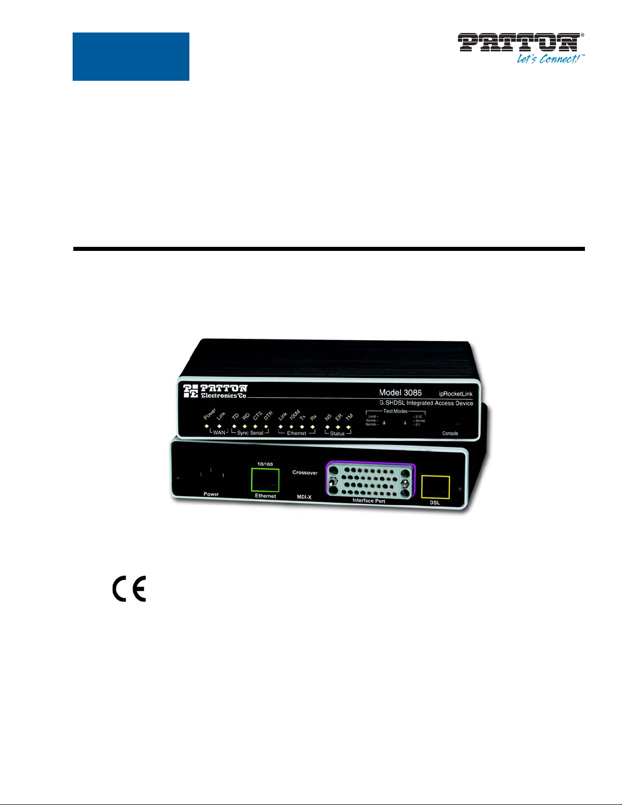
Model 3086
G.SHDSL Integrated
Access Device
User Guide
Important
This is a Class A device and is intended for use in a light industrial environment. It is not intended nor approved for use in an industrial
or residential environment.
Sales Office: +1 (301) 975-1000
Technical Support: +1 (301) 975-1007
E-mail: support@patton.com
WWW: www.patton.com
Part Number: 07M3086, Rev. E
Revised: February 16, 2012
Page 2

Patton Electronics Company, Inc.
7622 Rickenbacker Drive
Gaithersburg, MD 20879 USA
tel: +1 (301) 975-1000
fax: +1 (301) 869-9293
support: +1 (301) 975-1007
web: www.patton.com
e-mail: support@patton.com
Copyright © 2012, Patton Electronics Company. All rights reserved.
The information in this document is subject to change without notice. Patton Elec-
tronics assumes no liability for errors that may appear in this document.
Warranty Information
The software described in this document is furnished under a license and may be used
or copied only in accordance with the terms of such license.
Patton Electronics warrants all Model 3086 components to be free from defects, and
will—at our option—repair or replace the product should it fail within one year from
the first date of the shipment.
This warranty is limited to defects in workmanship or materials, and does not cover
customer damage, abuse or unauthorized modification. If the product fails to perform
as warranted, your sole recourse shall be repair or replacement as described above.
Under no condition shall Patton Electronics be liable for any damages incurred by
the use of this product. These damages include, but are not limited to, the following:
lost profits, lost savings and incidental or consequential damages arising from the use
of or inability to use this product. Patton Electronics specifically disclaims all other
warranties, expressed or implied, and the installation or use of this product shall be
deemed an acceptance of these terms by the user.
Page 3

Contents
Contents ......................................................................................................................................................... 3
About this guide ........................................................................................................................................... 11
Audience............................................................................................................................................................... 11
Structure............................................................................................................................................................... 11
Precautions........................................................................................................................................................... 12
Safety when working with electricity ...............................................................................................................13
Factory default parameters.................................................................................................................................... 13
Typographical conventions used in this document................................................................................................ 14
General conventions .......................................................................................................................................14
Mouse conventions .........................................................................................................................................14
1 General Information...................................................................................................................................... 15
Model 3086 G.SHDSL IAD overview...................................................................................................................16
General attributes ............................................................................................................................................16
G.SHDSL Characteristics ...............................................................................................................................17
Ethernet ..........................................................................................................................................................17
TDM Interface ...............................................................................................................................................17
Protocol support .............................................................................................................................................17
PPP Support ...................................................................................................................................................18
ATM Protocols ...............................................................................................................................................18
Protocol Support .............................................................................................................................................18
Management ...................................................................................................................................................18
Security ...........................................................................................................................................................19
Front Panel Status LEDs, Test Mode Switches, and Console Port ..................................................................19
Console port (outlined in red) ...................................................................................................................21
Rear panel connectors and switches .................................................................................................................21
Power connector .......................................................................................................................................21
AC universal power supply .................................................................................................................21
48 VDC power supply ........................................................................................................................21
Ethernet port (outlined in green) ...............................................................................................................22
MDI-X ......................................................................................................................................................22
Line port (outlined in yellow) ....................................................................................................................22
2 Product Overview.......................................................................................................................................... 23
Product Overview..................................................................................................................................................24
Applications Overview ....................................................................................................................................24
Internet/Extranet Access ............................................................................................................................25
IP/FR and TDM Access ............................................................................................................................25
IP/FR and Voice over DSL .......................................................................................................................25
Metro Intranet Access ...............................................................................................................................26
3 Quick Start Installation................................................................................................................................. 27
3
Page 4

Contents Model 3086 G.SHDSL Integrated Access Device User Guide
Hardware installation ............................................................................................................................................28
What you will need .........................................................................................................................................28
Installing the AC power cord ..........................................................................................................................28
Connecting network cables .............................................................................................................................29
IP address Quick Start modification ................................................................................................................30
Web Operation and Configuration .................................................................................................................30
PC Configuration .....................................................................................................................................30
Web Browser .............................................................................................................................................30
4 Basic Application Configurations.................................................................................................................. 33
Introduction..........................................................................................................................................................36
TDM Port.............................................................................................................................................................37
V.35 and X.21 Ports..............................................................................................................................................39
Connecting the 3086 serial port to a DTE ......................................................................................................39
Connecting the 3086 serial port to a DCE ......................................................................................................39
V.35 interfaces. .........................................................................................................................................39
X.21 interfaces. .........................................................................................................................................39
Configuring the V.35 or X.21 port via DIP switches ......................................................................................40
Switch Bank S2 .........................................................................................................................................42
Switches S2-1 through S2-7 ................................................................................................................42
Switch S2-8 ........................................................................................................................................43
Switch Bank S3 .........................................................................................................................................43
Switch S3-1: CO/CP selection ............................................................................................................43
Switch S3-3: Transmit Clock Mode ....................................................................................................44
T1 Interface...........................................................................................................................................................44
T1 Interface Connection .................................................................................................................................44
T1 Interface Configuration .............................................................................................................................45
DIP Switch Configuration ..............................................................................................................................45
Switch Bank S2 .........................................................................................................................................45
Switches S2-1 through S2-7 ................................................................................................................46
Switch S2-8 ........................................................................................................................................46
Switch Bank S3 .........................................................................................................................................47
Switch S3-1: CO/CP selection ............................................................................................................47
Switch S3-3: Transmit Clock Mode ....................................................................................................47
Switch S3-6: Annex ............................................................................................................................48
Switch S3-7 ........................................................................................................................................48
Switch S3-8 ........................................................................................................................................48
Switch S3 applies to E1 applications, for T1 applications this switch is ignored. .......................................48
Web Interface Configuration ....................................................................................................................48
E1 Interface...........................................................................................................................................................49
E1 Interface Connection .................................................................................................................................49
DIP Switch Configuration ..............................................................................................................................50
Switch Bank S2 .........................................................................................................................................50
Switch S2-8 ........................................................................................................................................51
4
Page 5

Model 3086 G.SHDSL Integrated Access Device User Guide Contents
Switch Bank S3 .........................................................................................................................................51
Switch S3-1: CO/CP selection ............................................................................................................51
Switch S3-3: Transmit Clock Mode ....................................................................................................52
Switch S3-6: Annex ............................................................................................................................52
Switch S3-7 ........................................................................................................................................52
Switch S3-8 ........................................................................................................................................52
Web Interface Configuration ....................................................................................................................53
Using the 3086 as a simple modem (TDM data over DSL)...................................................................................54
DIP Switch Configuration .............................................................................................................................54
CLI configuration ...........................................................................................................................................54
3086 A CLI configuration .........................................................................................................................54
3086 B CLI configuration .........................................................................................................................55
Web browser configuration .............................................................................................................................56
Circuit ID .................................................................................................................................................56
Clear Error Counters .................................................................................................................................56
Intended DSL Data Rate ...........................................................................................................................56
Actual DSL Rate .......................................................................................................................................56
Intended Serial Interface Data Rate ...........................................................................................................57
DSL Rate: Number of i Bit .......................................................................................................................57
Terminal Type ..........................................................................................................................................57
Interface Type ...........................................................................................................................................58
PCM Mode ...............................................................................................................................................58
PCM Transmit Polarity ............................................................................................................................58
PCM Receive Polarity ...............................................................................................................................58
Loopback ..................................................................................................................................................58
Annex Type ...............................................................................................................................................58
Line Probe .................................................................................................................................................58
TDM Plus Ethernet Traffic...................................................................................................................................58
CLI configuration ...........................................................................................................................................59
Selecting the DSL link speed .....................................................................................................................59
Selecting PCM mode ................................................................................................................................59
Assigning bandwidth to serial and Ethernet ports ......................................................................................59
Central or Remote terminal (Master/Slave) ...............................................................................................59
Interface Type ...........................................................................................................................................60
Annex Type ...............................................................................................................................................60
Web Browser Configuration ...........................................................................................................................60
Circuit ID .................................................................................................................................................61
Clear Error Counters .................................................................................................................................61
Intended DSL Data Rate ...........................................................................................................................61
Actual DSL Rate .......................................................................................................................................61
Intended Serial Interface Data Rate ...........................................................................................................62
DSL Rate: Number of i Bit .......................................................................................................................62
Terminal Type ..........................................................................................................................................62
Interface Type ...........................................................................................................................................63
5
Page 6

Contents Model 3086 G.SHDSL Integrated Access Device User Guide
PCM Mode ...............................................................................................................................................63
PCM Transmit Polarity ............................................................................................................................63
PCM Receive Polarity ...............................................................................................................................63
Loopback ..................................................................................................................................................63
Annex Type ...............................................................................................................................................63
Line Probe .................................................................................................................................................63
Using the 3086 in Routed or Bridged applications ................................................................................................64
Two stand-alone units directly connected .......................................................................................................64
Ethernet extension (HDLC – PPPOH) Bridged .......................................................................................64
Network Extension (HDLC—PPPoH Routed) ........................................................................................67
DSLAM Connections with remote CPE units.......................................................................................................73
Bridged application configurations to a DSLAM ............................................................................................73
RFC 1483 Bridged Configuration. ............................................................................................................73
PPPoH Bridged Configuration .................................................................................................................76
PPPoA Bridged (RFC 2364) Configuration ..............................................................................................79
Routed application configurations to a DSLAM .............................................................................................81
RFC 1483 Routed .....................................................................................................................................81
PPPoH Routed .........................................................................................................................................88
PPPoA Routed (RFC 2364) ......................................................................................................................95
IPoA Routed (RFC 1577) ......................................................................................................................107
5 Specialized Configurations.......................................................................................................................... 113
IP Configurations................................................................................................................................................114
Router ...........................................................................................................................................................114
DHCP Server and Relay ...............................................................................................................................114
6 Security ....................................................................................................................................................... 119
Introduction........................................................................................................................................................120
Configuring the IAD...........................................................................................................................................120
Configuring the security interfaces.......................................................................................................................121
Deleting a Firewall Policy .............................................................................................................................122
Enabling the Firewall...........................................................................................................................................123
Firewall Portfilters ...............................................................................................................................................123
Security Triggers..................................................................................................................................................124
Intrusion Detection System (IDS).......................................................................................................................126
7 NAT (Network Address Translation) .......................................................................................................... 129
Introduction........................................................................................................................................................130
Enabling NAT ..............................................................................................................................................130
Global address pool and reserved map ...........................................................................................................131
8 Monitoring Status ....................................................................................................................................... 133
Status LEDs.........................................................................................................................................................134
9 Diagnostics.................................................................................................................................................. 135
Introduction........................................................................................................................................................136
Ping.....................................................................................................................................................................136
6
Page 7

Model 3086 G.SHDSL Integrated Access Device User Guide Contents
Software Upgrades...............................................................................................................................................136
Configuration ...............................................................................................................................................136
Procedure ......................................................................................................................................................136
Operating Local Analog Loopback (LAL)—Serial Port Loop...............................................................................137
Operating Remote Digital Loopback (RDL)—DSL Loop...................................................................................137
T1/E1 Diagnostics...............................................................................................................................................138
Network Loop ..............................................................................................................................................138
T1/E1 Local Loop .........................................................................................................................................139
QRSS—BIT Error Rate Diagnostics .............................................................................................................140
T1/E1 connection Status ..............................................................................................................................141
Alarms .....................................................................................................................................................141
Transceiver Status. ..................................................................................................................................141
FDL statistics (T1 only) ..........................................................................................................................141
E1/T1 DS0 Monitor ...............................................................................................................................141
BIT Error Rate (V.52) Diagnostics......................................................................................................................142
10 Contacting Patton for assistance ................................................................................................................. 143
Introduction........................................................................................................................................................144
Contact information............................................................................................................................................144
Warranty Service and Returned Merchandise Authorizations (RMAs).................................................................144
Warranty coverage ........................................................................................................................................144
Out-of-warranty service ...........................................................................................................................144
Returns for credit ....................................................................................................................................144
Return for credit policy ...........................................................................................................................145
RMA numbers ..............................................................................................................................................145
Shipping instructions ..............................................................................................................................145
A Compliance information ............................................................................................................................ 147
Compliance.........................................................................................................................................................148
EMC .............................................................................................................................................................148
Safety ............................................................................................................................................................148
PSTN Regulatory ..........................................................................................................................................148
Radio and TV Interference (FCC Part 15) ..........................................................................................................148
CE Declaration of Conformity............................................................................................................................148
Authorized European Representative...................................................................................................................149
FCC Part 68 (ACTA) Statement .........................................................................................................................149
Industry Canada Notice ......................................................................................................................................149
B Specifications .............................................................................................................................................. 151
General Characteristics........................................................................................................................................152
G.SHDSL Characteristics....................................................................................................................................152
Ethernet ..............................................................................................................................................................152
Sync Serial Interface ............................................................................................................................................153
T1/E1 Interface (3086/RIK and RIT models only) .............................................................................................153
64K/G.703 Port (3086/RIF Model)...................................................................................................................153
Protocol Support .................................................................................................................................................153
7
Page 8

Contents Model 3086 G.SHDSL Integrated Access Device User Guide
PPP Support........................................................................................................................................................154
ATM Protocols....................................................................................................................................................154
Management .......................................................................................................................................................154
Security ...............................................................................................................................................................155
Compliance Standard Requirements....................................................................................................................155
Australia Specific .....................................................................................................................................155
Dimensions .........................................................................................................................................................155
Power and Power Supply Specifications...............................................................................................................155
AC universal power supply ......................................................................................................................155
48 VDC power supply ............................................................................................................................155
C Cable Recommendations ............................................................................................................................ 157
DSL Cable...........................................................................................................................................................158
Ethernet Cable ....................................................................................................................................................158
Adapter................................................................................................................................................................158
D Physical Connectors ................................................................................................................................... 159
RJ-45 shielded 10/100 Ethernet port...................................................................................................................160
RJ-11 non-shielded port......................................................................................................................................160
RJ-45 non-shielded RS-232 console port (EIA-561)............................................................................................160
Serial port............................................................................................................................................................161
V.35 (M/34 Connector) ...............................................................................................................................161
V.35 (DB-25 Female Connector) ..................................................................................................................161
X.21 (DB-15 Connector) ..............................................................................................................................162
E1/T1 (RJ-48C Connector) ..........................................................................................................................162
Power input.........................................................................................................................................................162
E Command Line Interface (CLI) Operation ................................................................................................ 163
Introduction........................................................................................................................................................164
CLI Terminology ................................................................................................................................................164
Local (VT-100 emulation) ............................................................................................................................164
Remote (Telnet) ............................................................................................................................................164
Using the Console .........................................................................................................................................165
Administering user accounts................................................................................................................................166
Adding new users ..........................................................................................................................................166
Setting user passwords ...................................................................................................................................166
Changing user settings ..................................................................................................................................167
Controlling login access ..........................................................................................................................167
Controlling user access ............................................................................................................................167
G.SHDSL Commands: .................................................................................................................................167
To establish the DSL link ........................................................................................................................168
F Interworking Functions Information ......................................................................................................... 171
Introduction........................................................................................................................................................173
Frame Relay Local Management Interface...........................................................................................................173
LMI Configuration Options: ........................................................................................................................173
8
Page 9

Model 3086 G.SHDSL Integrated Access Device User Guide Contents
managementType: (Default Value: no_maintenance) ..............................................................................173
MgtState .................................................................................................................................................174
mgtAutoStart: (Default Value: FALSE) ...................................................................................................174
T391_Value: (Default Value: 10) ............................................................................................................174
T392_Value: (Default Value: 16) ............................................................................................................174
fullReportCycle: (Default Value: 6) .........................................................................................................174
netErrorWindowSize: (Default Value: 4) ................................................................................................174
netMaxErrors: (Default Value: 3) ............................................................................................................174
userErrorWindowSize: (Default Value: 4) ...............................................................................................174
userMaxErrors: (Default Value: 3) ..........................................................................................................174
CLI Configuration Methods .........................................................................................................................175
Show current configuration .....................................................................................................................175
Set configuration variable ........................................................................................................................175
Web Configuration Methods ........................................................................................................................176
Frame Relay Service Interworking (FRF.8)..........................................................................................................176
FRS Configuration Options ..........................................................................................................................176
DE Mapping ...........................................................................................................................................176
FECN Mapping ......................................................................................................................................177
Translation Mode: ..................................................................................................................................177
FRS Name ..............................................................................................................................................178
CLI Configuration Method ..........................................................................................................................179
Show one of the eight groups ..................................................................................................................179
Set variable attributes on a specified group ..............................................................................................179
Set variable attributes on a specified channel ...........................................................................................180
Web Configuration Methods ........................................................................................................................180
FRS Overview Screen ..............................................................................................................................180
Group/Channel Level Configuration Screen ...........................................................................................181
Frame Relay Network Interworking (FRF.5).......................................................................................................182
FRN Configuration Options .........................................................................................................................182
Port Level Configuration Options: ..........................................................................................................183
Channel Level Configuration Options ..........................................................................................................184
CLI Configuration Methods for Port Level Management .............................................................................185
List all ports available to the system .........................................................................................................185
Show detailed information about a specific port ......................................................................................185
Set configuration variables associated with the specified port ...................................................................186
Configuration Management of the Channel Level Variables ....................................................................186
Understanding the Channel Level View ..................................................................................................186
Set Configuration Variables associated with the Channels .......................................................................187
Web Configuration Methods for FRF.5 Port and Channel Level Configuration ...........................................187
Port Level Information Screen .................................................................................................................188
Channel Level Information Screen ..........................................................................................................189
Packet Information Screen ......................................................................................................................189
Frame Relay (Ethernet Based) Operations...........................................................................................................190
Frame Relay Configuration Options .............................................................................................................190
9
Page 10

Contents Model 3086 G.SHDSL Integrated Access Device User Guide
Channel Segment Size .............................................................................................................................190
DLCI: Data Link Connection Identifier .................................................................................................190
Encapsulation Type .................................................................................................................................190
Port .........................................................................................................................................................190
Rxmaxpdu ...............................................................................................................................................190
Txmaxpdu ...............................................................................................................................................190
Frame Relay CLI Configuration Options ......................................................................................................190
Build a new Frame Relay Transport ........................................................................................................190
Clear all Frame Relay Transports ............................................................................................................191
Delete the specified transport ..................................................................................................................191
List all active Frame Relay Channels ........................................................................................................191
Set configuration variables for the specified frame relay transport ............................................................191
Show detailed configuration information on the specified channel: .........................................................191
Web Based Configuration of the Frame Relay Channel ................................................................................192
Serial Interface Configuration..............................................................................................................................192
Configuration Variables Available .................................................................................................................192
Clock Mode ............................................................................................................................................192
Clock Invert Functions: (rxClkInv – receive clock, txClkInv – transmit clock) ........................................192
Speed ......................................................................................................................................................192
CLI Configuration Methods .........................................................................................................................193
Set configuration variable ........................................................................................................................193
Show current configuration settings ........................................................................................................193
Gain help about the Serial Interface ........................................................................................................193
Web Interface Configurations .......................................................................................................................194
Ping and Trace Route..........................................................................................................................................194
Ping commands from the CLI Interface ........................................................................................................194
Trace Route from the CLI Interface ..............................................................................................................195
Define Usage: “ip traceroute” ..................................................................................................................195
Start Trace Route: “ip traceroute start 192.168.50.2” ..............................................................................195
Ping and traceroute from the web interface: ..................................................................................................196
Backup and Restore Features...............................................................................................................................196
Backup Configuration ...................................................................................................................................196
Restore Configuration ...................................................................................................................................196
10
Page 11

About this guide
This guide describes installing and configuring a Patton Electronics Model 3086 G.SHDSL Integrated Access
Device (IAD). The instructions in this guide are based on the following assumptions:
• The IAD may connect to a serial DTE device
• There is a LAN connected to the Ethernet port of the IAD
• Users will be connected to remote IADs
Audience
This guide is intended for the following users:
• Operators
• Installers
• Maintenance technicians
Structure
This guide contains the following chapters and appendices:
• Chapter 1 provides information about IAD features and capabilities
• Chapter 2 contains an overview describing IAD operation
• Chapter 3 provides quick start installation procedures
• Chapter 4 describes configuring the IAD for typical applications
• Chapter 5 describes configuring the IAD for specialized applications
• Chapter 6 describes configuring security for the IAD
• Chapter 7 describes configuring for network address translation (NAT)
• Chapter 8 contains definitions for the LED status indicators
• Chapter 9 describes IAD diagnostics
• Appendix B contains specifications for the IADs
• Appendix C provides cable recommendations
• Appendix D describes the IAD’s ports
• Appendix E describes how to use the command line interface (CLI)
For best results, read the contents of this guide before you install the IAD.
11
Page 12
About this guide Model 3086 G.SHDSL Integrated Access Device User Guide
Precautions
Notes and cautions, which have the following meanings, are used throughout this guide to help you become
aware of potential IAD problems. Warnings relate to personal injury issues, and Cautions refer to potential
property damage.
Note
Calls attention to important information.
The shock hazard symbol and WARNING heading indicate a potential electric
shock hazard. Strictly follow the warning instructions to avoid injury caused
by electric shock.
The alert symbol and WARNING heading indicate a potential safety hazard.
Strictly follow the warning instructions to avoid personal injury.
The shock hazard symbol and CAUTION heading indicate a
potential electric shock hazard. Strictly follow the instructions to
avoid property damage caused by electric shock.
The alert symbol and CAUTION heading indicate a potential hazard. Strictly follow the instructions to avoid property damage.
12
Page 13

Model 3086 G.SHDSL Integrated Access Device User Guide About this guide
Safety when working with electricity
•
This device contains no user serviceable parts. The equipment shall be
returned to Patton Electronics for repairs, or repaired by qualified service
personnel.
•
Mains Voltage: Do not open the case the when the power cord is attached.
Line voltages are present within the power supply when the power cords
are connected. The mains outlet that is utilized to power the devise shall be
within 10 feet (3 meters) of the device, shall be easily accessible, and pro
tected by a circuit breaker.
•
For AC powered units, ensure that the power cable used meets all applicable standards for the country in which it is to be installed, and that it is connected to a wall outlet which has earth ground.
•
For units with an external power adapter, the adapter shall be a listed Limited Power Source.
•
Hazardous network voltages are present in WAN ports regardless of
whether power to the unit is ON or OFF. To avoid electric shock, use caution
when near WAN ports. When detaching the cables, detach the end away
from the device first.
•
Do not work on the system or connect or disconnect cables during periods of
lightning activity.
-
In accordance with the requirements of council directive 2002/
96/EC on Waste of Electrical and Electronic Equipment (WEEE),
ensure that at end-of-life you separate this product from other
waste and scrap and deliver to the WEEE collection system in
your country for recycling.
Factory default parameters
The Model 3086 G.SHDSL IAD has the following factory default parameters.
• Ethernet IP address: 192.168.200.10/24
• WAN Connection: PPPoH Bridged
• Autonegotiate the G.SHDSL speed
• Ethernet and serial connections
• Annex B
• Remote (CPE)
• MDI (LAN connector)
• Switch configuration disabled
13
Page 14
About this guide Model 3086 G.SHDSL Integrated Access Device User Guide
Typographical conventions used in this document
This section describes the typographical conventions and terms used in this guide.
General conventions
The procedures described in this manual use the following text conventions:
Table 1. General conventions
Convention Meaning
Futura bold type Indicates the names of menu bar options.
Italicized Futura type Indicates the names of options on pull-down menus.
Futura type
Garamond bold type Indicates the names of command buttons that execute an action.
< >
Are you ready? All system messages and prompts appear in the Courier font as the
% dir *.* Bold Courier font indicates where the operator must type a response or
Indicates the names of fields or windows.
Angle brackets indicate function and keyboard keys, such as <SHIFT>,
<CTRL>, <C>, and so on.
system would display them.
command
Mouse conventions
The following conventions are used when describing mouse actions:
Table 2. Mouse conventions
Convention Meaning
Left mouse button This button refers to the primary or leftmost mouse button (unless you have
changed the default configuration).
Right mouse button This button refers the secondary or rightmost mouse button (unless you have
changed the default configuration).
Point This word means to move the mouse in such a way that the tip of the pointing
arrow on the screen ends up resting at the desired location.
Click Means to quickly press and release the left or right mouse button (as instructed in
the procedure). Make sure you do not move the mouse pointer while clicking a
mouse button.
Double-click Means to press and release the same mouse button two times quickly
Drag This word means to point the arrow and then hold down the left or right mouse but-
ton (as instructed in the procedure) as you move the mouse to a new location.
When you have moved the mouse pointer to the desired location, you can release
the mouse button.
14
Page 15

Chapter 1 General Information
Chapter contents
Model 3086 G.SHDSL IAD overview...................................................................................................................16
General attributes ............................................................................................................................................16
G.SHDSL Characteristics ...............................................................................................................................17
Ethernet ..........................................................................................................................................................17
TDM Interface ...............................................................................................................................................17
Protocol support .............................................................................................................................................17
PPP Support ...................................................................................................................................................18
ATM Protocols ...............................................................................................................................................18
Protocol Support .............................................................................................................................................18
Management ...................................................................................................................................................18
Security ...........................................................................................................................................................19
Front Panel Status LEDs, Test Mode Switches, and Console Port ..................................................................19
Console port (outlined in red) ...................................................................................................................21
Rear panel connectors and switches .................................................................................................................21
Power connector .......................................................................................................................................21
AC universal power supply.................................................................................................................. 21
48 VDC power supply ........................................................................................................................ 21
Ethernet port (outlined in green) ...............................................................................................................22
MDI-X ......................................................................................................................................................22
Line port (outlined in yellow) ....................................................................................................................22
15
Page 16

1 • General Information Model 3086 G.SHDSL Integrated Access Device User Guide
Model 3086 G.SHDSL IAD overview
The Model 3086 is a G.SHSDSL Integrated Access Device that combines high-speed IP routing and access via
ATM/FR/PPP along with TDM data access. The model 3086 offers direct connection to a 10/100Base-T
Ethernet environment, a V.35/X.21 Serial direct connection to a router or multiplexer, or a T1, E1, or
64K/G.703 port for connection to local device (e.g., PBX).
The Model 3086 complies with ETSI/ITU standard G.991.2 and allows full duplex, up to 2.3 Mbps speed
over a single twisted pair. In addition, the Model 3086 works at up to 4.6 Mbps over 2-wire. Whereas G.991.2
specifies 4-wire for data rates from 2.3 to 4.6 Mbps, the 3086 is able to operate up to 4.6
2
wires! Speed setting ranges are user selectable in nx64 kbps increments from 64 kbps.
The following sections describe Model 3086 features and capabilities:
• General attributes, see page 16
• G.SHDSL Characteristics (Model 3086), see page 17
• Ethernet, see page 17
• Protocol support, see page 17
• PPP support, see page 18
• ATM protocols, see page 18
Mbps over jsut
• Management, see page 18
• TDM Interface, see page 17
• Security, see page 19
• Front panel status LEDs, switches, etc., see page 19
General attributes
• Compact, low cost IAD
• 10/100 Ethernet
• Unlimited host support.
• Comprehensive hardware diagnostics, works with any operating system, easy maintenance and effortless
installation.
• Plug-and-Play operation for fast and seamless turn-up with pre-configured WAN and LAN options.
• Built-in web configuration.
• Setup allows for standard IP address and unique method for entering an IP address and mask WITHOUT
use of a console connection. Default IP address of 192.168.1.1/24.
• Simple software upgrade using FTP into FLASH memory.
• Twelve front panel LEDs indicate , DSL WAN, Sync Serial, Ethernet LAN speed and status, and Test
mode status.
• Convenient and standard RJ connectors for Ethernet, Line, and Console.
• Field Factory Default Option.
16 Model 3086 G.SHDSL IAD overview
Page 17

Model 3086 G.SHDSL Integrated Access Device User Guide 1 • General Information
• Standard 1 year warranty.
• Convenient and standard RJ connectors for Ethernet, Line, and Console.
G.SHDSL Characteristics
• Full duplex 2.3 Mbps speed over 2-wire (in accordance with ETSI/ITU standard G.991.2). 2.3 Mbps to
4.6 Mbps, full duplex, over 2-wire.
• DTE rates 64 kbps to 2.3 Mbps operation (Sync serial can work in increments of 64 kbps up to a band-
width of 2.3 Mbps, n=32).
• Distance from 24,900 feet (7,590 m) at 192 kbps to 10,200 ft (3,109 m) at 2.3 Mbps on 26 AWG (0.4
mm) wire
• Annex A (ANSI), Annex B (ETSI) PSD selection.
• CO and CP modes supported
• TC-PAM based DSL modulations.
• EOC Management channel for remote end-to-end management.
Ethernet
• Auto-sensing Full-Duplex 10Base-T/100Base-TX Ethernet.
• Standard RJ-45 connector
• Built-in MDI-X cross-over switch.
• IEEE 8021.d transparent learning bridge up to 1,024 addresses and Spanning Tree.
• 8 IP address/subnets on Ethernet interface.
TDM Interface
• V.35, X.21, or T1/E1 interface
• Available with female M/34, DB-25, DB-15, and RJ-48C connectors
• User configurable DTE/DCE for X.21
Protocol support
• Complete internetworking with IP (RFC 741), TCP (RFC 793), UDP (RFC 768), ICMP (RFC 950),
ARP (RFC 826).
• IP Router with RIP (RFC 1058), RIPv2 (RFC 2453) for up to 64 static routes.
• Built-in Ping and Traceroute facilities.
• Integrated DHCP Server (RFC 2131).
• DHCP relay agent (RFC 2132/RFC 1542) with 8 individual address pools.
• DNS Relay with primary and secondary Name Server selection.
• NAT (RFC 3022) with Network Address Port Translation (NAPT), MultiNat with 1:1, Many:1,
Many:Many mapping, Port/IP redirection and mapping.
Model 3086 G.SHDSL IAD overview 17
Page 18

1 • General Information Model 3086 G.SHDSL Integrated Access Device User Guide
PPP Support
• Point-to-Point Protocol over HDLC
• PPPoA (RFC 2364) Point-to-Point Protocol over ATM.
• PPPoE (RFC 2516) Client for autonomous network connection. Eliminates the requirement of installing
client software on a local PC and allows sharing of the connection across a LAN.
• User configurable PPP PAP (RFC 1661) or CHAP (RFC 1994) authentication..
ATM Protocols
• Multiprotocol over ATM AAL5 and Multiprotocol Bridged encapsulation RFC 2684 (Formerly RFC
1483) and RFC 1577 Classical IP over ATM. Default RFC-1483 route mode. Logical Link Control
(LLC)/ Subnetwork Access Protocol (SNAP) encapsulation. Default VC mux mode.
• ATM UNI 3.0, 3.1, and 4.0 signaling ATM QoS with UBR, CBR, nrt-VBR, and rt-VBR.
• Peak cell rate shaping on a per-VCC basis up to 32 active VCCs across VPI 0-255, VCI 0-65525. Single
default PVC: 8/35 with PCR=5,500 cells.
Protocol Support
• Complete internetworking with IP (RFC 741), TCP (RFC 793), UDP (RFC 768), ICMP (RFC 950),
ARP (RFC 826).
• IP Router with RIP (RFC 1058), RIPv2 (RFC 2453),
• Up to 64 static routes with user selectable priority over RIP/OSPF routes.
• Built-in ping facilities.
• Integrated DHCP Server (RFC 2131). Selectable general IP leases and user specific MAC/IP parings.
Selectable lease period.
• DHCP relay agent (RFC 2132/RFC 1542) with 8 individual address pools.
• DNS Relay with primary and secondary Name Server selection.
• NAT (RFC 3022) with Network Address Port Translation (NAPT) for cost-effective sharing of a single
DSL connection. Integrated Application Level Gateway with support for over 80 applications.
• NAT MultiNat with 1:1 mapping.
• NAT Many:1.
• NAT Many:Many mapping.
• NAT Port/IP redirection and mapping.
• uPNP controlled device for seamless networked device interconnectivity and Windows XP integration.
• IGMPv2 Proxy support (RFC 2236).
• Frame Relay with Annex A/D/LMI, RFC 1490 MpoFR and FRF.12 Fragmentation.
Management
• User selectable ATM, PPP, or Frame Relay WAN datalink connection.
• Web-Based configuration via embedded web server
• CLI menu for configuration, management, and diagnostics.
• Local/Remote CLI (VT-100 or Telnet).
18 Model 3086 G.SHDSL IAD overview
Page 19
Model 3086 G.SHDSL Integrated Access Device User Guide 1 • General Information
• SNMPv1 (RFC 1157) MIB II (RFC 1213)
• Quick Start Setup runs through common options to simplify circuit turn-up.
• Logging via SYSLOG, and VT-100 console. Console port set at 9600 bps 8/N/1 settings no flow control.
• EOC access for End-To-End management, configuration, and control.
Security
• Packet filtering firewall for controlled access to and from LAN/WAN. Support for 255 rules in 32 filter sets.
16 individual connection profiles.
• DoS Detection/protection. Intrusion detection, Logging of session, blocking and intrusion events and
Real-Time alerts. Logging or SMTP on event.
• Password protected system management with a username/password for console and virtual terminal. Sepa-
rate user selectable passwords for SNMP RO/RW strings.
• Access list determining up to 5 hosts/networks which are allowed to access management system
SNMP/HTTP/TELNET.
• Logging or SMTP on events: POST, POST errors, line/DSL, PPP/DHCP, IP.
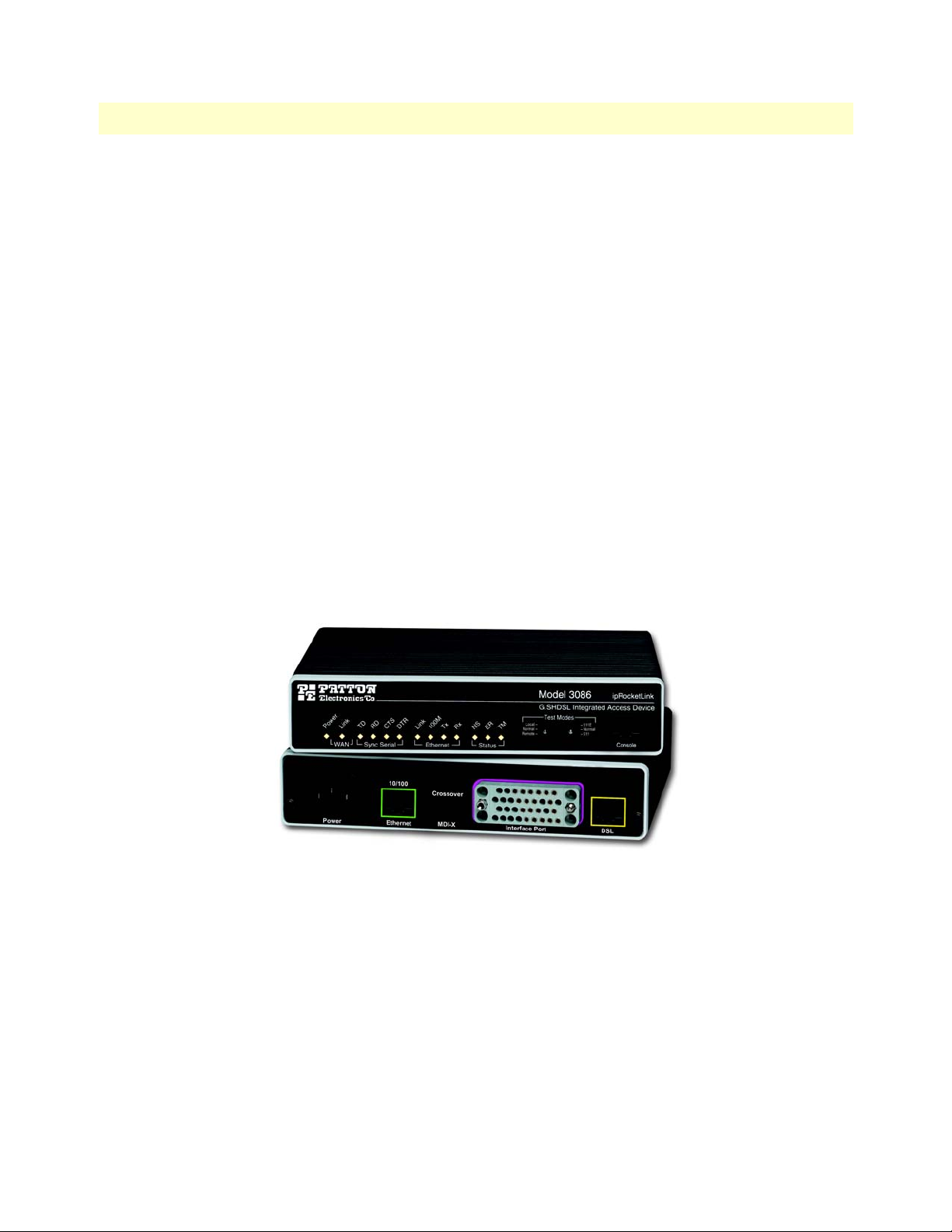
Front Panel Status LEDs, Test Mode Switches, and Console Port
The IpRocketLink routers have all status LEDs and console port on the front panel of the unit, and all other
electrical connections are located on the rear panel.
Figure 1. Model 3086
The status LEDs from left to right are (see table 3 for LED descriptions):
• Power
• WAN Link (DSL)
• Sync Serial (TD, RD, CTS, and DTR) or T1/E1 (Link, LOSS, TD, and RD)
• Ethernet Link, 100M, Tx, and Rx
• Status NS, ER, and TM
Model 3086 G.SHDSL IAD overview 19
Page 20

1 • General Information Model 3086 G.SHDSL Integrated Access Device User Guide
Table 3. Status LED descriptions
Power Green ON indicates that power is applied. Off indicates
that no power is applied.
WAN (D SL) Link Green Solid green: connected
Off: disconnected
Sync Serial TD Green Green: indicates a binary ‘0’ condition
off: indicates a binary ‘1’or idle condition
RD Green Green: indicates a binary ‘0’condition
off: indicates a binary ‘1’ or idle condition
CTS Green ON: indicates the CTS signal from the IAD is
active, binary ‘1’
off: indicates CTS is binary ‘0’
DTR Green ON: indicates the DTR signal from the DTE device
attached to the serial port is active, binary ‘1’
T1/E1 Link Green On: indicates the T1/E1 interface is connected to a
live T1/E1 line
LOS Red On: indicates a T1/E1 loss-of-frame condition. It
also indicates that no T1/E1 signal is detected.
TD Green Green: indicates a binary ‘0’ condition
off: indicates a binary ‘1’or idle condition
RD Green Green: indicates a binary ‘0’condition
off: indicates a binary ‘1’ or idle condition
Ethernet Link Green ON: indicates an active 10/100 BaseT connection
100M Green ON: connected to a 100BaseT LAN
Off: connected to a 10BaseT LAN
Tx Green Flashing: when transmitting data from the IAD to
the Ethernet
Rx Green Flashing: when transmitting data from the Ethernet
to the IAD.
Status NS Red ON: incidates absence of a valid DSL connection
ER Red flashes once: indicates bit errors occurring during
511/511E tests
TM Yellow ON: is under one of the test modes (local loop,
remote loop, or V.54 BER pattern)
The test mode switches are:
• Normal, Local, and Remote Loopbacks
• Normal, 511, and 511E pseudo-random bit patterns
20 Model 3086 G.SHDSL IAD overview
Page 21
Model 3086 G.SHDSL Integrated Access Device User Guide 1 • General Information
Console port (outlined in red)
The unshielded RJ-45 RS-232 console DCE port (EIA-561) with the pin-out listed in the following table:
Pin No. Signal Direction Signal Name
1 Out DSR
2 Out CD
3 In DTR
4 — Signal Ground
5 Out RD
6 In TD
7 Out CTS
8 In RTS
Rear panel connectors and switches
On the rear panel from left to right are the following:
• Power input connector
• Ethernet connector
• MDI-X switch
• TDM port. V.35 (3086/C), X.21 (3086/D), T1/E1 (3086/K)
• Line connector
Power connector
AC universal power supply.
The Model 3086 offers internal or external AC power supply options.
• The internal power supply connects to an AC source via an IEC-320 connector (100–240 VAC, 200 mA,
50/60 Hz)
• The external power supply connects to an external source providing +5 VDC via a barrel-type connector
48 VDC power supply.
• Rated voltage and current: 36–60 VDC, 400 mA
• Fuse rating: 250 Volts, 400 mA, time delay
Connect the equipment to a 36–60 VDC source that is electrically isolated from the AC source. The 36–60 VDC source is to
be reliably connected to earth.
Model 3086 G.SHDSL IAD overview 21
Page 22
1 • General Information Model 3086 G.SHDSL Integrated Access Device User Guide
Ethernet port (outlined in green)
Shielded RJ-45 10Base-T/100Base-TX Ethernet port using pins 1,2,3, & 6. See MDI-X switch for hub or transceiver
configuration.The following table defines conditions that occur when the MDI-X switch is in the out position.
Pin No. Signal Direction Signal Name
1 Output TX+
2 Output TX3 Input RX+
4 — —
5 — —
6 Input RX7 — —
8 — —
MDI-X
The MDI-X push switch operates as follows:
• When in the default “out” position, the Ethernet circuitry takes on a straight-through MDI configuration
and functions as a transceiver. It will connect directly to a hub.
• When in the “in” position, the Ethernet circuitry is configured in cross-over MDI-X mode so that a
straight-through cable can connect the Model 3086 DSL modem’s Ethernet port directly to a PC’s NIC
card.
Line port (outlined in yellow)
The RJ-11/4 DSL line port uses pins 2 and 3 of the RJ-11 port.
Pin No. Signal Name
1 —
2 In/Out-A
3 In/Out-B
4 —
22 Model 3086 G.SHDSL IAD overview
Page 23

Chapter 2 Product Overview
Chapter contents
Product Overview..................................................................................................................................................24
Applications Overview ....................................................................................................................................24
Internet/Extranet Access ............................................................................................................................25
IP/FR and TDM Access ............................................................................................................................25
IP/FR and Voice over DSL .......................................................................................................................25
Metro Intranet Access ...............................................................................................................................26
23
Page 24

2 • Product Overview Model 3086 G.SHDSL Integrated Access Device User Guide
Product Overview
The Model 3086 IAD operates as a bridge or a router and has three ports for communication:
• The Ethernet port—Connects to the LAN side of the connection
• The Line port—Provides the G.SHDSL transmission connection between the CPE and CO DSL IAD
• The TDM port—Connects to local devices for data uplink over the main DSL link
The IAD provides all layer 2 and layer 3 protocols required for end-to-end-link communication.
When configuring the 3086, questions must be answered so the 3086 functions as desired. For example, when
a router or bridge module needs to be activated, some questions would be:
• Is a default gateway required?
• Which encapsulation technique is best for this application: PPPoA, Frame Relay, PPPoE or another?
These decisions can be made and implemented more easily if the Model 3086’s fundamental architecture is
understood. Also, while configuring the Model 3086 via a browser using the built-in HTTP server is very intui
tive, an understanding of the architecture is essential when using the command-line interface (CLI) commands.
The fundamental building blocks comprise a router or bridge, interfaces, and transports. The router and bridge
each have interfaces. A transport provides the path between an interface and an external connection. For exam
ple, the Ethernet transport attaches to an Internet Protocol (IP) interface. A transport consists of layer 2 and
everything below it. Creating a transport and attaching it to a bridge or router’s interface enables data to be
bridged or routed. The supported transports are PPPoA, PPPoE, Frame Relay, RFC 1483 (Multiprotocol
Encapsulation over ATM AAL5), IPoA, PPPoH, and Ethernet.
-
-
Configuring an interface and transport for the router or bridge requires naming the interface and transport before
attaching them. When using the built-in HTTP server web browser, this is done automatically. But when config
uring the Model 3086 via CLI commands through the RS-232 control port, it must be done manually.
Model 3086 IADs can connect over an ATM PVC or HDLC transport.
The PVC requires the configuration of the virtual path identifier (VPI) and virtual circuit identifier (VCI). The
VPI can be any integer between 0–4095 inclusive. The general rule for the VCI is an integer between 1–65,535
inclusive. Examples in this manual use a VCI of 600 or above. The main restriction in choosing a VCI is that
VCIs below 32 are reserved for such predefined functions as ILMI. The VCI values of 600 and above used in
this manual are also above the range used by many signaling implementations for SVCs.
The HDLC is a packet-based transmission across the DSL Link.
Several ATM connections are offered to address a variety of user applications. Although they all use RFC1483
as the transport mechanism between the two 3086 IADs, WAN services may use different PPP applications,
such as PPPoE routed, PPPoA routed, or PPPoA bridged. Each one has its advantages and disadvantages.
Applications Overview
The Model 3086 IAD is geared to the connection of small to medium size enterprises in Internet (connection
to ISP), or connection of remote branches using DSL access and IP/FR/ATM/PPP. In most applications, the
Model 3086 works with Patton’s 3096RC ForeFront System, but it will also connect to third-party G.SHDSL
devices.
-
24 Product Overview
Page 25
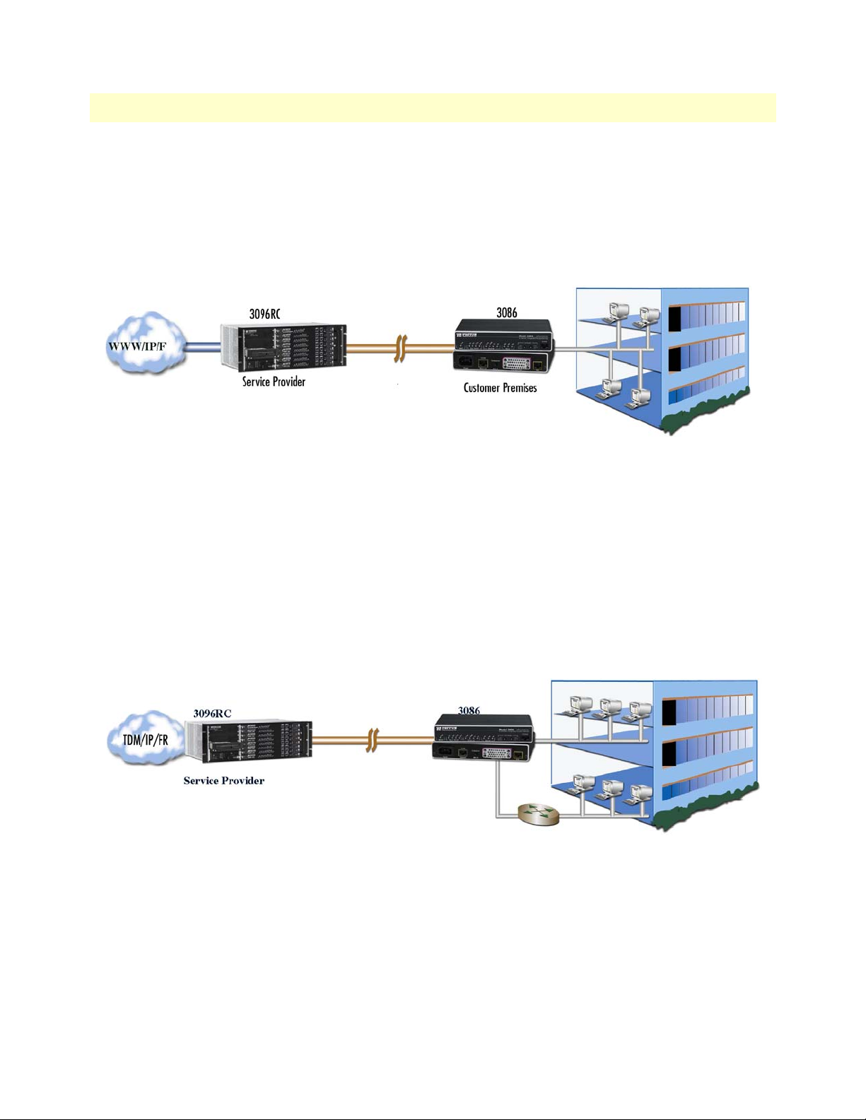
Model 3086 G.SHDSL Integrated Access Device User Guide 2 • Product Overview
Internet/Extranet Access
While Frame Relay (FR) remains the most economical service to connect multiple corporate locations over
PVCs (Private Virtual Connections) at burst and fixed data rates, high speed DSL is becoming the technology
of choice for last mile access to FR switches. The Model 3086 connects to a 10/100Base-T hub or switch at the
customer’s LAN, while at the network side it connects to Patton’s 3096RC via a 2-wire DSL Link. Data from
the 3086 links is concentrated by the 3096RC and sent over the WAN via DS1, DS3, or STS links.
At the Data Link Layer, The Model 3086 encapsulates IP data from the customer LAN into FR packets and
transmits over the DSL link to a Service Provider location. Inside the provider’s network, VCs transport data
across the WAN to their final destination. Additionally, the Model 3086 supports PPP encapsulation, FR to
ATM network internetworking, or FR to ATM Service internetworking.
IP/FR and TDM Access
The Model 3086 goes a step further, along with providing IP/FR/ATM/PPP connectivity for a 10/100 Ethernet LAN, it also comes with a local serial port for connection to a router or multiplexer. Using Patton’s
FlexIP™ technology, serial (TDM) data from a router, and IP data from the 3086’s Ethernet port is trans
ported in splits DSL bandwidth mode. The serial port provides logical and physical segmentation and access in
a multiple office campus environment
IP/FR and Voice over DSL
The Model 3086 can also connect to a PBX. Along with providing IP/FR/ATM/PPP connectivity for a 10/100
Ethernet LAN, the 3086/RIK’s drop-and-insert port connects to a local PBX to provide voice and data solu
-
tion in one simple to use box. Using Patton’s FlexIP™ technology, IP data from an Ethernet environment, and
Product Overview 25
Page 26
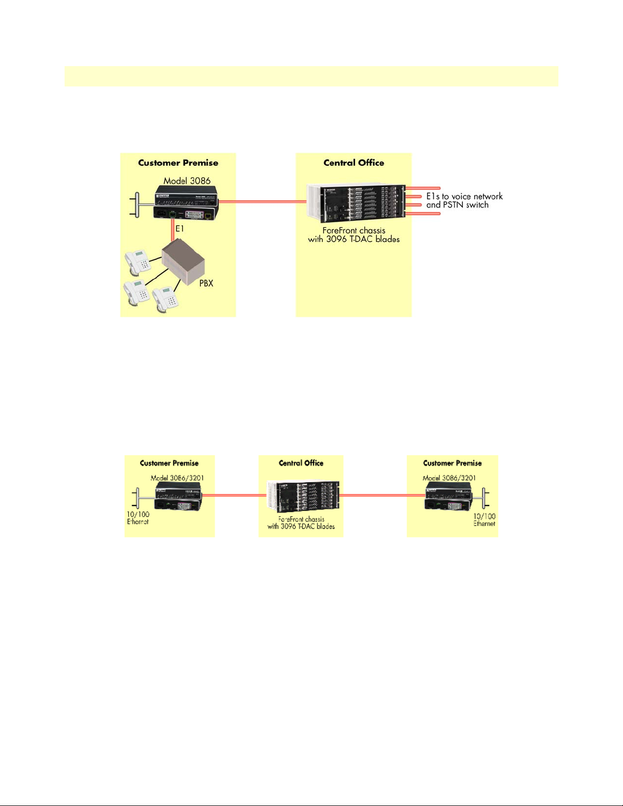
2 • Product Overview Model 3086 G.SHDSL Integrated Access Device User Guide
PCM encoded voice from a PBX are carried in split-DSL- bandwidth mode to a Central Office. At a Service
Provider location the Model 3096RC separates PCM voice and IP data traffic for transport over the WAN
Metro Intranet Access
Patton’s Model 3086 symmetrical G.SHDSL modulation scheme, allows deployment in back-to-back configurations for Metro Intranet Access with the following benefits.
• Low cost creation of VPN and Intranet Access
• Can be connected locally or via TDM networks
• Secure networking and more efficient Traffic Engineering
26 Product Overview
Page 27

Chapter 3 Quick Start Installation
Chapter contents
Hardware installation ............................................................................................................................................28
What you will need .........................................................................................................................................28
Installing the AC power cord ..........................................................................................................................28
Connecting network cables .............................................................................................................................29
IP address Quick Start modification ................................................................................................................30
Web Operation and Configuration .................................................................................................................30
PC Configuration .....................................................................................................................................30
Web Browser .............................................................................................................................................30
27
Page 28
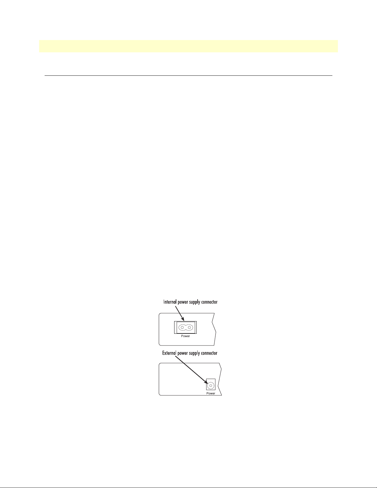
3 • Quick Start Installation Model 3086 G.SHDSL Integrated Access Device User Guide
Hardware installation
If you are already familiar with Model 3086 IAD installation and configuration, this chapter will enable you to
finish the job quickly. Installation consists of the following:
• Preparing for the installation (see section “What you will need”)
• Hooking up cables, verifying that the unit will power up, and running a HyperTerminal session (see section
“Connecting network cables” on page 29)
• Changing the IP address from the factory default setting (see section “IP address Quick Start modification”
on page 30)
• Launching a web browser in preparation for configuring the modem (see “Web Operation and Configura-
tion” on page 30)
What you will need
• Model 3086 G.SHDSL IAD
• Ethernet cable with RJ45 plugs on each end (included with IAD)
• DB9-RJ45 Adapter (included with IAD)
• RJ45/RJ45 straight-through cable for connecting to control port (included with IAD)
• PC computer with HyperTerminal or equivalent VT-100 emulation program, or an ASCII (“dumb”) terminal.
Installing the AC power cord
This section describes installing the power cord into the IEC-320 connector on the 3086. Do not connect the
male end of the power cord to the power outlet at this time. Do the following:
1. Install the power cable into Power connector (see figure 2). The AC main socket outlet shall be within 10
feet (3 meters) of the equipment and shall be easily accessible.
Figure 2. Power connector location on rear panel
28 Hardware installation
Page 29

Model 3086 G.SHDSL Integrated Access Device User Guide 3 • Quick Start Installation
To avoid the risk of injury from electric shock, the power cord connected to the
IEC-320 connectors must be a grounded power cord.
The 3086 power supply automatically adjusts to accept an input
voltage from 100 to 240 VAC (50/60 Hz).
Verify that the proper voltage is present before plugging the
power cord into the receptacle. Failure to do so could result in
equipment damage.
2. Verify that the AC power cord included with your 3086 is compatible with local standards. If it is not,
refer to
Chapter 10, “Contacting Patton for assistance” on page 27 to find out how to replace it with a
compatible power cord.
3. Connect the male end of the power cord to an appropriate power outlet.
4. Verify that the green POWER LED is lit.
5. Unplug the AC power cord from the Model 3086 to power down the unit.
Connecting network cables
Except for the Console port, all connectors are on the rear panel of the ipRocketLink with the exception of the
power connection. The Ethernet port is Green and the Line is Yellow. The Console port is the only electrical
connection on the front panel.
Do the following:
1. Connect the DB9-RJ45 adapter to the DB-9 serial port on the PC or dumb terminal. Use the RJ45-RJ45
straight-through cable between the adapter and the red marked RJ45 port on the 3086 IAD.
2. Do NOT connect the IAD to the Ethernet LAN now.
3. On the PC, start a HyperTerminal session at 9600 bps, 8 data bits, 1 stop bit, and no parity.
4. Plug the AC power cord into the Model 3086 to power up the IAD.
5. Type superuser for Login:, and press Enter.
6. Then type superuser for the password, press Enter.
7. A message will display, “Login Successful.” By typing the character “?”, all the commands will be dis-
played. Any commands parameters may be seen by entering the command followed by a space and a question mark.
fi
ethernet ?
add
delete
set
show
list
clear
[The following parameters appear]
Hardware installation 29
Page 30

3 • Quick Start Installation Model 3086 G.SHDSL Integrated Access Device User Guide
IP address Quick Start modification
The first parameter to change is the IP address from the default IP address of 192.168.1.1/24 (for the CP
units) or 192.168.200.11 (for CO units) to your selected IP address. Follow these steps. Comments are in
brackets […].
fi
ip list interfaces <enter>
IP Interfaces:
ID | Name | IP Address | DHCP | Transport
-------|---------------|------------------|-------------|----------------- 1 | ip1 | 192.168.200.10 | disabled | <bridge>
---------------------------------------------------------------------------
fi
ip set interface ip1 ipaddress 192.168.100.2 255.255.255.0 <enter>
[lists the characteristics of the different interfaces]
[Sets the new IP address which you have selected.
The IP address in this example is for illustrative purposes only.]
fi
ip list interfaces <enter>
fi
system config save <enter>
Wait for “configuration saved” message…
Saving configuration
fi
Configuration saved.
<enter>
fi
[To see if the change in IP address is correct]
[To save the new IP address in flash memory.]
The IP address has now been successfully changed.
Web Operation and Configuration
Now that the IP address has been configured for your application, you can complete the configuration using
any standard web browser.
PC Configuration
In order to connect the PC to the Ethernet LAN to communicate with the Model 3086, the PC’s IP address
should be on the same subnet as the modem.
Connect a straight-through Ethernet cable between the PC’s NIC or PCMCIA Ethernet card and an Ethernet
hub or switch.
Web Browser
Do the following:
1. Launch a standard web browser such as Netscape Communicator or Internet Explorer (IE).
2. Enter the 3086’s IP address into the URL or Address field of the browser.
30 Hardware installation
Page 31

Model 3086 G.SHDSL Integrated Access Device User Guide 3 • Quick Start Installation
The Model 3086 home page displays (see Figure 3).
Figure 3. Model 3086 home page
The Model 3086 menu structure is shown in figure 4 on page 32.
Hardware installation 31
Page 32

3 • Quick Start Installation Model 3086 G.SHDSL Integrated Access Device User Guide
Figure 4. Model 3086 Menu Structure
32 Hardware installation
Page 33

Chapter 4 Basic Application Configurations
Chapter contents
Introduction..........................................................................................................................................................36
TDM Port.............................................................................................................................................................37
V.35 and X.21 Ports..............................................................................................................................................39
Connecting the 3086 serial port to a DTE ......................................................................................................39
Connecting the 3086 serial port to a DCE ......................................................................................................39
V.35 interfaces. .........................................................................................................................................39
X.21 interfaces. .........................................................................................................................................39
Configuring the V.35 or X.21 port via DIP switches ......................................................................................40
Switch Bank S2 .........................................................................................................................................42
Switches S2-1 through S2-7 ................................................................................................................ 42
Switch S2-8......................................................................................................................................... 43
Switch Bank S3 .........................................................................................................................................43
Switch S3-1: CO/CP selection ............................................................................................................ 43
Switch S3-3: Transmit Clock Mode.................................................................................................... 44
T1 Interface...........................................................................................................................................................44
T1 Interface Connection .................................................................................................................................44
T1 Interface Configuration .............................................................................................................................45
DIP Switch Configuration ..............................................................................................................................45
Switch Bank S2 .........................................................................................................................................45
Switches S2-1 through S2-7 ................................................................................................................ 46
Switch S2-8......................................................................................................................................... 46
Switch Bank S3 .........................................................................................................................................47
Switch S3-1: CO/CP selection ............................................................................................................ 47
Switch S3-3: Transmit Clock Mode.................................................................................................... 47
Switch S3-6: Annex............................................................................................................................. 48
Switch S3-7......................................................................................................................................... 48
Switch S3-8......................................................................................................................................... 48
Switch S3 applies to E1 applications, for T1 applications this switch is ignored. .......................................48
Web Interface Configuration ....................................................................................................................48
E1 Interface...........................................................................................................................................................49
E1 Interface Connection .................................................................................................................................49
DIP Switch Configuration ..............................................................................................................................50
Switch Bank S2 .........................................................................................................................................50
Switch S2-8......................................................................................................................................... 51
Switch Bank S3 .........................................................................................................................................51
Switch S3-1: CO/CP selection ............................................................................................................ 51
Switch S3-3: Transmit Clock Mode.................................................................................................... 52
Switch S3-6: Annex............................................................................................................................. 52
Switch S3-7......................................................................................................................................... 52
33
Page 34

4 • Basic Application Configurations Model 3086 G.SHDSL Integrated Access Device User Guide
Switch S3-8......................................................................................................................................... 52
Web Interface Configuration ....................................................................................................................53
Using the 3086 as a simple modem (TDM data over DSL)...................................................................................54
DIP Switch Configuration .............................................................................................................................54
CLI configuration ...........................................................................................................................................54
3086 A CLI configuration .........................................................................................................................54
3086 B CLI configuration .........................................................................................................................55
Web browser configuration .............................................................................................................................56
Circuit ID .................................................................................................................................................56
Clear Error Counters .................................................................................................................................56
Intended DSL Data Rate ...........................................................................................................................56
Actual DSL Rate .......................................................................................................................................56
Intended Serial Interface Data Rate ...........................................................................................................57
DSL Rate: Number of i Bit .......................................................................................................................57
Terminal Type ..........................................................................................................................................57
Interface Type ...........................................................................................................................................58
PCM Mode ...............................................................................................................................................58
PCM Transmit Polarity ............................................................................................................................58
PCM Receive Polarity ...............................................................................................................................58
Loopback ..................................................................................................................................................58
Annex Type ...............................................................................................................................................58
Line Probe .................................................................................................................................................58
TDM Plus Ethernet Traffic...................................................................................................................................58
CLI configuration ...........................................................................................................................................59
Selecting the DSL link speed .....................................................................................................................59
Selecting PCM mode ................................................................................................................................59
Assigning bandwidth to serial and Ethernet ports ......................................................................................59
Central or Remote terminal (Master/Slave) ...............................................................................................59
Interface Type ...........................................................................................................................................60
Annex Type ...............................................................................................................................................60
Web Browser Configuration ...........................................................................................................................60
Circuit ID .................................................................................................................................................61
Clear Error Counters .................................................................................................................................61
Intended DSL Data Rate ...........................................................................................................................61
Actual DSL Rate .......................................................................................................................................61
Intended Serial Interface Data Rate ...........................................................................................................62
DSL Rate: Number of i Bit .......................................................................................................................62
Terminal Type ..........................................................................................................................................62
Interface Type ...........................................................................................................................................63
PCM Mode ...............................................................................................................................................63
PCM Transmit Polarity ............................................................................................................................63
PCM Receive Polarity ...............................................................................................................................63
Loopback ..................................................................................................................................................63
Annex Type ...............................................................................................................................................63
34
Page 35

Model 3086 G.SHDSL Integrated Access Device User Guide 4 • Basic Application Configurations
Line Probe .................................................................................................................................................63
Using the 3086 in Routed or Bridged applications ................................................................................................64
Two stand-alone units directly connected .......................................................................................................64
Ethernet extension (HDLC – PPPOH) Bridged .......................................................................................64
Network Extension (HDLC—PPPoH Routed) ........................................................................................67
DSLAM Connections with remote CPE units.......................................................................................................73
Bridged application configurations to a DSLAM ............................................................................................73
RFC 1483 Bridged Configuration. ............................................................................................................73
PPPoH Bridged Configuration .................................................................................................................76
PPPoA Bridged (RFC 2364) Configuration ..............................................................................................79
Routed application configurations to a DSLAM .............................................................................................81
RFC 1483 Routed .....................................................................................................................................81
PPPoH Routed .........................................................................................................................................88
PPPoA Routed (RFC 2364) ......................................................................................................................95
IPoA Routed (RFC 1577) ......................................................................................................................107
35
Page 36

4 • Basic Application Configurations Model 3086 G.SHDSL Integrated Access Device User Guide
Introduction
The Model 3086 IAD comes with two data ports: a TDM (V.35, X.21, or T1/E1), and an Ethernet port.
TDM port data is not processed by the router or bridge core in the 3086, data is transmitted unprocessed over
the DSL link. Data from the Ethernet port is processed by the 3086 bridge or router core and sent inHDLC or
ATM encapsulation over the DSL link.
The 3086 can be used as a simple modem – transporting TDM data from a router, multiplexer, or PBX connected to the V.35, X.21 or T1/E1 port. In this case the user configures DSL and TDM port features only.
The 3086 can concurrently transport TDM and Ethernet traffic, the TDM and Ethernet ports are activated,
and the user must assign DSL bandwidth for both TDM and Ethernet traffic. Since Ethernet layer is activated,
the user must configure the routing or bridging features and must choose from HDLC or ATM encapsulation
The 3086 can be used to transport Ethernet traffic only, via its 10/100 Base-T LAN across a campus or across
a WAN, in this case, the TDM port is not activated. In addition to configuring the DSL link, the user must
configure the routing or bridging features and must choose from HDLC or ATM encapsulation.
Configuration for these applications is presented in the following sections. The 3086 is used to transport TDM
data only, TDM plus Ethernet, or Ethernet only data. Since the configuration of the router or bridge and the
ATM or HDLC Features are considerably more complex than the DSL and data port layers, we present physi
cal layer configuration of TDM port and TDM port plus Ethernet first as the foundation from which the
upper layers can be configured. An extensive section is devoted to the Bridge/Router, and HDLC/ATM appli
cation configuration.
-
-
What follows is a brief description and a table summarizing the parameters for bridged and routed WAN services achieved with the Model 3086.
The basic applications are divided according to whether the application is bridged or routed.
The bridged applications are RFC 1483 Bridged, PPPoA Bridged, and HDLC Bridged.
The routed applications are RFC 1483, PPPoA, IPoA, PPPoE, and HDLC.
Another way of organizing the applications is according to the type of encapsulation: PPP, RFC 1483, or Frame
Relay. PPP encapsulation is available as PPPoA bridged or routed and PPPoE. RFC 1483 and Frame Relay can
be configured for bridged and routed connections.
36 Introduction
Page 37

Model 3086 G.SHDSL Integrated Access Device User Guide 4 • Basic Application Configurations
The following table shows the parameters that can be configured via the HTTP server using a web browser.
Routed WAN Services Bridged WAN Services
Web Page Parameter RFC
Description X X X X X X X X
VPI X X X X X X default = 0
VCI X X X X X X default = 35
Encapsulation X X Llc or VcMux
Use DHCP X X X
WAN IP address X X X default mask = 255.255.255.0
LLC header X X X
HDLC header X X X X X
No authentication X X X
PAP X X X
CHAP X X X
User Name X X X
Password X X X
WAN IP address (Local IP) X
Access Concentrator X
Service Name X
DLCI X X default = 1
FR HDLC Encapsulation X X Routed: IP or raw
Bridged: BridgedEther,
BridgedEtherCRC, or Raw.
PPPoA IPoA PPPoE HDLC RFC
1483
(0.0.0.0)
1483
PPPoA HDLC
Local IP Mask = 255.255.255.0
TDM Port
Model 3086 units enable V.35, X.21, or T1/E1 interface connection to local routers, multiplexers, or PBX
devices. The V.35 interface is presented either on a M/34, or DB-25 female connectors. The X.21 interface is pre
-
TDM Port 37
Page 38

4 • Basic Application Configurations Model 3086 G.SHDSL Integrated Access Device User Guide
sented on a female DB-15 connector, while the T1/E1 interface is presented on an RJ-48C jack, additionally the
E1 interface is presented on dual BNC.
Figure 5 shows the different connectors offered for the serial port.
Figure 5. Rear panel power and interface connectors
38 TDM Port
Page 39

Model 3086 G.SHDSL Integrated Access Device User Guide 4 • Basic Application Configurations
V.35 and X.21 Ports
The serial port in the 3086 is simple to install. The V.35 interface is wired as a DCE, the X.21 interface can be
configured as a DCE (factory default), or as a DTE via internal configuration jumper. The following sections
describe the 3086 X.21 and V.35 port connection to DTE and DCE devices.
Connecting the 3086 serial port to a DTE
The serial port on the Model 3086 is configured as a DCE so it connects directly to a DTE using a standard
straight through cable. The cable should present either a male M/34 or DB-25 connector on one end, for V.35
interfaces, or a male DB-15 for X.21 interface connection. The other end should be terminated with the appro
priate connector ( check your DTE equipment manual for pinout, gender, and DTE/DCE port configuration).
Connecting the 3086 serial port to a DCE
V.35 interfaces.
The V.35 interface in the 3086 is wired as a DCE, no DTE configuration is possible. If the equipment that the
3086 is connecting to locally does not have the option for DTE configuration, a tail-circuit cable will be
required (this cable is available from most datacomm supply vendors). The tail-circuit cable will cross most
interface signals, so that the DCE interface of the 3086 and the DCE interface of the third party equipment
can function properly. Please be aware that some third party equipment will not be able to work properly in
DCE to DCE configurations even when using a tail circuit cable (please refer to your third party equipment
user manual for information on DCE-to DCE operation). The 3086 requires a cable with a male M/34 or
male DB-25 connector.
-
X.21 interfaces.
The Model 3086’s X.21 interface configuration can be modified, by the user, as DCE (factory default) or
DTE, via an internal jumper board. When the local third party equipment is configured as DCE, the Model
3086 X.21 serial port can be configured as DTE, and a regular straight through cable can then be used. Do the
following to configure the X.21 port as a DTE:
1. Open the 3086’s case by inserting a screwdriver into the slots and twist the screwdriver head slightly. The
top half of the case will separate from the lower half of the case (see
Figure 6). Take caution not to damage
any of the PC board mounted components.
Figure 6. Case being opened with screwdriver
V.35 and X.21 Ports 39
Page 40

4 • Basic Application Configurations Model 3086 G.SHDSL Integrated Access Device User Guide
2. Locate the small daughter board on the 3086 board between the DSL port (RJ-45) connector and the
serial port connector (
Figure 7 shows location of DTE/DCE daughter board).
Figure 7. Location of DCE/DTE board
3. The DTE/DCE daughter board is installed at the factory with the DCE label and arrows pointing towards
the X.21 connector (DCE configuration). To change to DTE configuration, lift the daughter board from
the connector, turn it around so that the DTE label an arrows point to the X.21 connector, and place it
back on the connector. The X.21 port is now configured as a DTE.
Note
When the X.21 port is configured as a DTE, the clocking mode for
the port must be set for external clock.
Configuring the V.35 or X.21 port via DIP switches
The 3086 TDM port can be configured via terminal interface, web interface, or DIP switches. This section
describes configuring the TDM port via DIP switches only. Please note that DIP switches modify serial port
features only.
40 V.35 and X.21 Ports
Page 41
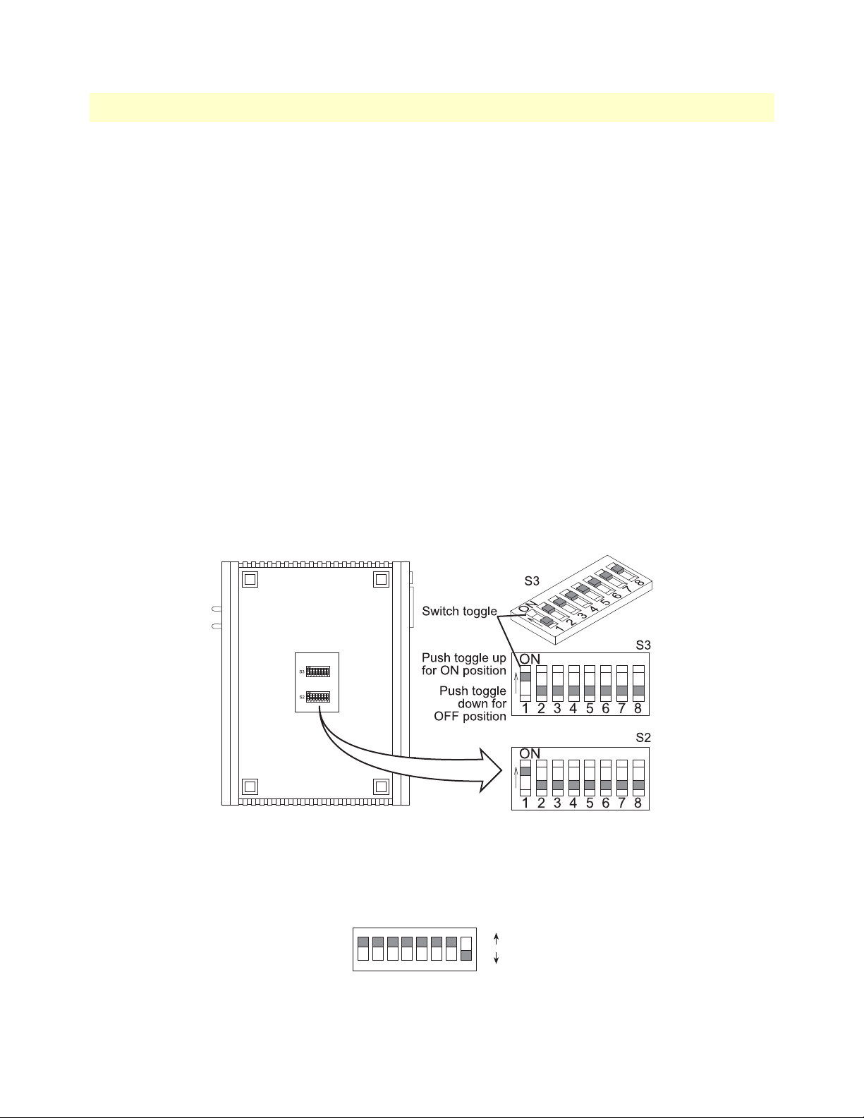
Model 3086 G.SHDSL Integrated Access Device User Guide 4 • Basic Application Configurations
F
Switch configuration: Switch configuration in the 3086 is to be used in situations where the 3086 functions as
a DSL modem carrying TDM (X.21, V.35) data only, without resorting to the use of a PC for configuration.
When configuring the Model 3086 via DIP switches, the following conditions apply:
• Speed selected applies to the Sync Serial port, not to the Ethernet port
• PCM Mode will be set to Serial only
• DSL interface will be set to HDLC
• To enable DIP witch operation, begin by setting up the DSL rate (units are shipped with switches in the On
position —corresponding to CLI/Web management).
• Implementation of DIP switch settings can be done in two ways:
- Set up DIP switches and then cycle power On/Off/On.
- Set up DIP switches and then turn the implementation switch (S2-8) to the Off position, wait 3 to 4 sec-
onds, turn S2-8 back to On (you do not need to cycle the power for the unit).
• To put the unit back to CLI/Web management, ALL DIP switches must be set to the On position.
The Model 3086 includes two eight-DIP switch banks labeled S2 and S3. They are externally accessible by
removing the plate on the bottom side of the unit.
Figure 8 shows the location of the DIPswitches on the bot-
tom of the printed circuit board.
Figure 8. DIP switches location
DIP switches S2 and S3 can be configured as either “On” or “Off”. Figure 9 shows the orientation of the DIP
switches with respect to the ON/OFF positions.
ON
12345678
Figure 9. Close-up of DIP switches showing ON/OFF positions
V.35 and X.21 Ports 41
ON
OF
Page 42
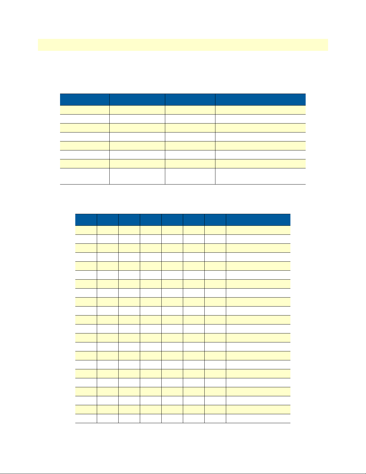
4 • Basic Application Configurations Model 3086 G.SHDSL Integrated Access Device User Guide
Switch Bank S2
Table 4 shows the default configuration for switch S2. A description of S2 options follows the table.
Table 4. S2 Summary Table
Switch Position Function Factory Default Selected Option
S2-1 Serial Rate On Not a valid rate
S2-2 On
S2-3 On
S2-4 On
S2-5 On
S2-6 On
S2-7 On
S2-8 Switch configuration On Toggle On->Off>On
To activate DIP configuration
Switches S2-1 through S2-7. Use Switches S2-1 through S2-7 to set the data rate. Each position represents
nx64 settings.
S7 S6 S5 S4 S3 S2 S1 Data Rate (kbps)
On On On On On On Off 64
On On On On On Off On 128
On On On On On Off Off 192
On On On On Off On On 256
On On On On Off On Off 320
On On On On Off Off On 384
On On On On Off Off Off 448
On On On Off On On On 512
On On On Off On On Off 576
On On On Off On Off On 640
On On On Off On Off Off 704
On On On Off Off On On 768
On On On Off Off On Off 832
On On On Off Off Off On 896
On On On Off Off Off Off 960
On On Off On On On On 1024
On On Off On On On Off 1088
On On Off On On Off On 1152
On On Off On On Off Off 1216
On On Off On Off On On 1280
On On Off On Off On Off 1344
On On Off On Off Off On 1408
42 V.35 and X.21 Ports
Page 43

Model 3086 G.SHDSL Integrated Access Device User Guide 4 • Basic Application Configurations
S7 S6 S5 S4 S3 S2 S1 Data Rate (kbps)
On On Off On Off Off Off 1472
On On Off Off On On On 1536
On On Off Off On On Off 1600
On On Off Off On Off On 1664
On On Off Off On Off Off 1728
On On Off Off Off On On 1792
On On Off Off Off On Off 1856
On On Off Off Off Off On 1920
On On Off Off Off Off Off 1984
On Off On On On On On 2048
On Off On On On On Off 2112
On Off On On On Off On 2176
On Off On On On Off Off 2240
On Off On On Off On On 2304
Switch S2-8. S2-8 activates configuration of Model 3086 via DIP switches. Any time the user desires to modify the 3086 configuration available through DIP switches, make the changes to the corresponding switches
and then set S2-8, from On to Off position, wait 3-4 seconds and set back to the On position. Changes made
to configuration via DIP switches will not take effect if S2-8 isn’t toggled.
S2-8 Condition
ON->Off->ON Implements switch configuration (toggled ON/OFF)
Switch Bank S3
The table below shows the default configuration for switch S3. A description of S3 options follows this table.
Table 5. S3 Summary Table
Switch Position Function Factory Default Selected Option
S3-1 CO/CP Selection On CO
S3-2 Reserved On Reserved
S3-3 Clock On External
S3-4 Reserved On Reserved
S3-5 Reserved On Reserved
S3-6 Annex Off = Annex A
On = Annex B
S3-7 Reserved On Reserved
S3-8 Reserved On Reserved
Annex B
Switch S3-1: CO/CP selection. CO and CP stand for Central Office and Customer Premise respectively.
When deploying the model 3086s, units installed at the Customer location should be set to CP and units
V.35 and X.21 Ports 43
Page 44

4 • Basic Application Configurations Model 3086 G.SHDSL Integrated Access Device User Guide
installed at a Central Office should be set to CO. For point-to-point operation, one unit must be CO while the
other must be CP.
S3-3 Setting
Off CP
ON CO
Switch S3-3: Transmit Clock Mode. Use Switches S3-3 to configure the Model 3086 for internal or external
clock mode (keep in mind that this setting only affects the operation of the serial port).
S3-3 Clock mode
Off Internal. Transmit Clock to DTE is generated internally by the Model 3086
On External. Transmist Clock to DTE is generated from external clock signal received
from DTE. (This option is only available when the Model 3086 is set to CO mode.
T1 Interface
The 3086 enables T1 or E1 device located at customer locations to access a carrier’s network over two wire,
long reach DSL links. This capability allows providers to offer T1/E1 services at customer locations that were
previously outside the reach of standard T1/E1 lines.
The 3086/K offers a user configurable T1 or E1 interface. Selection of the interface is done via DIP switches,
HTTP/SNMP, or command line interface (CLI).
The T1 interface is an eight position keyed modular jack configured as a RJ-48C for connection to 100-ohm
twisted pair lines.
Figure 10. 3086 T1 port pinout
T1 Interface Connection
The 3086 will usually connect either to a local T1 device, or to a Telco terminated T1 line jack.
• To connect the 3086’s T1 port to a local T1 device ( PBX, router, mux) use a T1 ‘crossover’ twisted pair
cable. A crossover cable connects the transmit pins of the Model 3086’s T1 port to the receive pins of the
device attached to this port and vice versa. Check the third party T1 equipment documentation for pinout
information and cable requirements.
• To connect the 3086’s T1 port to a Telco terminated T1 line jack, use a straight through twisted pair patch
cable. Consult with your T1 service provider for exact pinout information and cable requirements.
44 T1 Interface
Page 45

Model 3086 G.SHDSL Integrated Access Device User Guide 4 • Basic Application Configurations
T1 Interface Configuration
The 3086 T1 interface can be configured via DIP switches, HTTP/SNMP, or command line interface (CLI).
This section discusses DIP switches and HTTP (web server) configuration. For CLI, see Appendix D,
“Com-
mand Line Interface (CLI) Operation” on page 163.
DIP Switch Configuration
Switch configuration in the 3086 is to be used in situations where the 3086 functions as a DSL modem carrying TDM (T1) data only without resorting to the use of a PC for configuration.
Note
The Model 3086 is shipped with all DIP switches set to the ON position. While in this setting, the Model 3086 can be configured only
via software (console, Telnet, HTTP, SNMP). If you want to use the
DIP switches to configure the Model 3086, see section
“Switch S2-8”
on page 43 to activate the DIP switch configuration option.
The Model 3086 includes two eight-DIP switch banks labeled S2 and S3. They are externally accessible by
removing the plate on the bottom side of the unit.
Switch Bank S2
Table 6 shows the default configuration for switch S2. A description of S2 options follows the table.
Table 6. S2 Summary Table
Switch Position Function Factory Default Selected Option
S2-1 Data Rate On Not a valid rate
S2-2 On
S2-3 On
S2-4 On
S2-5 On
S2-6 On
S2-7 On
S2-8 Switch configuration On Toggle On->Off>On
To activate DIP configuration
T1 Interface 45
Page 46

4 • Basic Application Configurations Model 3086 G.SHDSL Integrated Access Device User Guide
Switches S2-1 through S2-7. Use Switches S2-1 through S2-7 to set the data rate (see Table 5 on page 43.
Each position represents nx64 settings.
S7 S6 S5 S4 S3 S2 S1 Data Rate (kbps)
On On On On On On Off 64
On On On On On Off On 128
On On On On On Off Off 192
On On On On Off On On 256
On On On On Off On Off 320
On On On On Off Off On 384
On On On On Off Off Off 448
On On On Off On On On 512
On On On Off On On Off 576
On On On Off On Off On 640
On On On Off On Off Off 704
On On On Off Off On On 768
On On On Off Off On Off 832
On On On Off Off Off On 896
On On On Off Off Off Off 960
On On Off On On On On 1024
On On Off On On On Off 1088
On On Off On On Off On 1152
On On Off On On Off Off 1216
On On Off On Off On On 1280
On On Off On Off On Off 1344
On On Off On Off Off On 1408
On On Off On Off Off Off 1472
On On Off Off On On On 1536
Switch S2-8. S2-8 activates configuration of Model 3086 via DIP switches. Any time the user desires to modify the 3086 configuration available through DIP switches, make the changes to the corresponding switches
and then set S2-8, from On to Off position, wait 3-4 seconds and set back to the On position. Changes made
to configuration via DIP switches will not take effect if S2-8 isn’t toggled.
S2-8 Condition
ON->Off->ON Implements switch configuration (toggled ON/OFF)
46 T1 Interface
Page 47

Model 3086 G.SHDSL Integrated Access Device User Guide 4 • Basic Application Configurations
Switch Bank S3
The table below shows the default configuration for switch S3. A description of S3 options follows this table.
Table 7. S3 Summary Table
Switch Position Function Factory Default Selected Option
S3-1 CO/CP Selection On CO
S3-2 Reserved On Reserved
S3-3 Clock On Network
S3-4 Reserved On Reserved
S3-5 Reserved On Reserved
S3-6 Annex Off = Annex A
On = Annex B
S3-7 Reserved On Reserved
S3-8 Reserved On Reserved
Annex B
Switch S3-1: CO/CP selection. CO and CP stand for Central Office and Customer Premise respectively.
When deploying the model 3086s, units installed at the Customer location should be set to CP and units
installed at a Central Office should be set to CO. For point-to-point operation, one unit must be CO while the
other must be CP.
S3-3 Setting
Off CP
ON CO
Switch S3-3: Transmit Clock Mode. Use Switches S3-3 to configure the 3086 for internal or external (network) clock mode.
S3-3 Clock mode
Off Internal. DSL and T1 transmit clock generated by the 3086
On External. DSL and T1 transmit clock derived from the received T1 signal (CO con-
figuration only)
T1 Interface 47
Page 48

4 • Basic Application Configurations Model 3086 G.SHDSL Integrated Access Device User Guide
Switch S3-6: Annex. Annex A and B offer spectral compatibility with T1 and E1 signals respectively, this feature reduces the interference between DSL lines and adjacent E1or T1 lines. For regions where T1 is used,
select Annex A.
S3-6 Annex
Off Annex A
On Annex B
Switch S3-7. Use S3-7 to configure the TDM interface for T1 or E1 service. Note that selecting E1 automatically sets the E1 line rate to HDB3, line impedance to 120-Ohms. Selecting T1 automatically sets the framing
to Extended Super Frame and B8ZS line code.
S3-7 Configuration
Off E1 mode (HDB3)
On T1 mode (ESF/B8ZS)
Switch S3-8. Switch S3 applies to E1 applications, for T1 applications this switch is ignored.
Web Interface Configuration
The T1 interface page is accesed from the Main Menu > E1/T1. This page allows configuration of T1
paraemeters as follows:
Time Slot Select. For a T1 using all 24 time slots, enter 1-24, for fractional T1 enter in any format for example: 1,2,3,5; or 1-5,10-24. Any entry for timeslots above 24 will return and invalid selection message.
Line Options: Fractional T1
Line Code: The 3086 T1 interface uses B8ZS
48 T1 Interface
Page 49

Model 3086 G.SHDSL Integrated Access Device User Guide 4 • Basic Application Configurations
Line Build Out: Select from 100 ohm (0dB), 100 ohm (-7.5dB), 100 ohm (-15dB), and 100 ohm (-22.5dB).
For CSU/DSU application use 100 0dB option, consult your T1 service provider for more information.
FDL Mode: Options are ANSI-T1-403, ATT-54016, and Fdl-none. Consult your T1 service provider or third
party equipment for FDL mode required.
Idle code: Enabled, Disabled. When enabled, the 2603 inserts idle codes on unused timeslots. Set this option
to ‘Disabled’ unless instructed otherwise.
Power Down: Normal, Powered Down. When powered down, T1/E1 transceiver input and output lines will
be set to high impedance to protect the device—set unit to “Normal” for regular operation.
Once all options have been selected, click on the
Configure and Activate
at the bottom of the screen. Addition-
ally, save the configuration by going to the Configuration > Save Config menu.
E1 Interface
The 3086 enables T1 or E1 device located at customer locations to access a carrier’s network over two wire,
long reach DSL links. This capability allows providers to offer T1/E1 services at customer locations that were
previously outside the reach of standard T1/E1 lines.
The 3086 offers a user configurable T1 or E1 interface. Selection of the interface is done via DIP switches,
HTTP/SNMP, or command line interface (CLI).
The E1 interface is presented on both a modular, 8-pin RJ-48C jack for connection to 120-ohm twisted pair
lines, and dual BNC female connectors for connection to 75-ohm coaxial lines.
Figure 11. E1 interface with RJ-48C jack (120–ohm) and dual BNC (75-ohm) connectors
E1 Interface Connection
The 3086 will usually connect either to a local E1 device, or to a Telco terminated E1 line jack.
• To connect to the 3086 E1 port and a local E1 device (PBX, router, mux) use a E1 ‘crossover’ twisted pair
cable. A crossover cable connects the transmit pins of the Model 3086’s E1 port to the receive pins of the
device attached to this port and vice versa. Check the third party E1 equipment documentation for pinout
E1 Interface 49
Page 50

4 • Basic Application Configurations Model 3086 G.SHDSL Integrated Access Device User Guide
information and cable requirements. If the E1 connection is made via the BNC connectors, connect the TX
BNC of the 3086 to Recive (RX) BNC of the local E1 device, and vice versa.
• To connect the 3086’s E1 port to a Telco terminated E1 line jack, use a straight through twisted pair patch
cable. Consult with your E1 service provider for exact pinout information and cable requirements.
The 3086 T1/E1 port can be configured via DIP switches, HTTP/SNMP, or command line interface (CLI).
This section discusses DIP switches and HTTP (web server) configuration, for CLI and SNMP information
see
Appendix E on page 163.
DIP Switch Configuration
Switch configuration in the 3086 is to be used in situations where the 3086 functions as a DSL modem carrying TDM (E1) data only without resorting to the use of a PC for configuration.
Note
The Model 3086 is shipped with all DIP switches set to the ON position. While in this setting, the Model 3086 can be configured only
via software (console, Telnet, HTTP, SNMP). If you want to use the
DIP switches to configure the Model 3086, see section
“Switch S2-8”
on page 43 to activate the DIP switch configuration option.
The Model 3086 includes two eight-DIP switch banks labeled S2 and S3. They are externally accessible by
removing the plate on the bottom side of the unit.
Switch Bank S2
A description of S2 options follows the table.
S7 S6 S5 S4 S3 S2 S1 Data Rate (kbps)
On On On On On On Off 64
On On On On On Off On 128
On On On On On Off Off 192
On On On On Off On On 256
On On On On Off On Off 320
On On On On Off Off On 384
On On On On Off Off Off 448
On On On Off On On On 512
On On On Off On On Off 576
On On On Off On Off On 640
On On On Off On Off Off 704
On On On Off Off On On 768
On On On Off Off On Off 832
On On On Off Off Off On 896
On On On Off Off Off Off 960
On On Off On On On On 1024
On On Off On On On Off 1088
On On Off On On Off On 1152
50 E1 Interface
Page 51
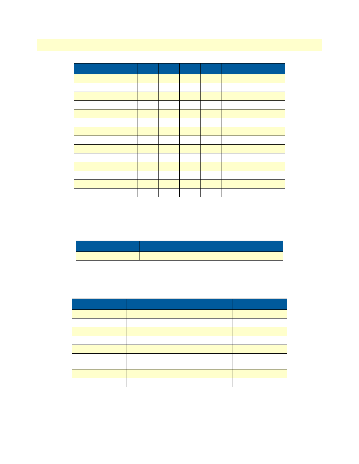
Model 3086 G.SHDSL Integrated Access Device User Guide 4 • Basic Application Configurations
S7 S6 S5 S4 S3 S2 S1 Data Rate (kbps)
On On Off On On Off Off 1216
On On Off On Off On On 1280
On On Off On Off On Off 1344
On On Off On Off Off On 1408
On On Off On Off Off Off 1472
On On Off Off On On On 1536
On On Off Off On On Off 1600
On On Off Off On Off On 1664
On On Off Off On Off Off 1728
On On Off Off Off On On 1792
On On Off Off Off On Off 1856
On On Off Off Off Off On 1920
On On Off Off Off Off Off 1984
On Off On On On On On 2048
Switch S2-8. S2-8 activates configuration of Model 3086 via DIP switches. Any time the user desires to modify the 3086 configuration available through DIP switches, make the changes to the corresponding switches
and then set S2-8, from On to Off position, wait 3-4 seconds and set back to the On position. Changes made
to configuration via DIP switches will not take effect if S2-8 isn’t toggled.
S2-8 Condition
ON->Off->ON Implements switch configuration (toggled ON/OFF)
Switch Bank S3
The table below shows the default configuration for switch S3. A description of S3 options follows this table.
Table 8. S3 Summary Table
Switch Position Function Factory Default Selected Option
S3-1 CO/CP Selection On CO
S3-2 Reserved On Reserved
S3-3 Clock On External
S3-4 Reserved On Reserved
S3-5 Reserved On Reserved
S3-6 Annex Off = Annex A
On = Annex B
S3-7 T1/E1 On T1
S3-8 E1/CRC On No CRC
Annex B
Switch S3-1: CO/CP selection. CO and CP stand for Central Office and Customer Premise respectively.
When deploying the model 3086s, units installed at the Customer location should be set to CP and units
E1 Interface 51
Page 52

4 • Basic Application Configurations Model 3086 G.SHDSL Integrated Access Device User Guide
installed at a Central Office should be set to CO. For point-to-point operation, one unit must be CO while the
other must be CP.
S3-3 Setting
Off CP
ON CO
Switch S3-3: Transmit Clock Mode. Use Switches S3-3 to configure the 3086 for internal or external clock
mode.
S3-3 Clock mode
Off Internal. Transmit clock generated by the 3086
On External (network). DSL and E1 transmit clock derived from the received E1 signal
(available in CO mode only)
Switch S3-6: Annex. Annex A and B offer spectral compatibility with T1 and E1 signals respectively, this feature reduces the interference between DSL lines and adjacent E1or T1 lines. For regions where E1 is used,
select Annex B.
S3-6 Annex
Off Annex A
On Annex B
Switch S3-7. Use S3-7 to configure the TDM interface for T1 or E1 service. Note that selecting E1 automatically sets the E1 line rate to HDB3, line impedance to 120-ohms. Selecting T1 automatically sets the framing
to Extended Super Frame and B8ZS line code.
S3-7 Configuration
Off E1 mode (HDB3)
On T1 mode (ESF/B8ZS)
Switch S3-8. Switch S3-8 applies to E1 applications only. This switch selects whether the E1 link will use
CRC or not while in framed mode. In Clear Channel mode (unframed) this switch is ignored.
S3-8 Setting
Off E1 with CRC
ON E1 without CRC
52 E1 Interface
Page 53

Model 3086 G.SHDSL Integrated Access Device User Guide 4 • Basic Application Configurations
Web Interface Configuration
Launch Internet Explorer or similar web browser, type the IP address of the 2603, enter username ‘superuser’
and password ‘superuser’. From the main page click on the E1/T1 option > Configuration. This page allows
configuration of E1 parameters as follows:
Time Slot Select. For unframed E1 service (Clear Channel) enter time slots 0-31. For a full framed E1 enter 131, for partially filled E1 enter the range of timeslots using the format for example: 1,2,3,5; or 1-5,10-31. Any
entry for timeslots above 31 will return and invalid selection message.
Line Options: Choose from Clear Channel E1, Fractional E1, Fractional E1, Multi-Frame(CAS) E1, MultiFrame(CAS) E1 with CRC. Consult with your service provider which option is required.
Line Code: Choose from AMI or HDB3. Most E1 applications use HDB3
Line Build Out: Select 120 ohm if the E1 connection is made via the RJ-48C connector, select 75 Ohm if the
E1 connection is made via the Dual BNC connectors.
FDL Mode: FDL is a T1 application, therefore select ‘Fdl- none’ for E1 applications.
Idle code: Options are Enabled or Disabled. When idle code is Enabled, the 3086/K inserts idle codes on
E1unused timeslots. Set this option to ‘Disabled’ unless instructed otherwise.
Power Down: Options are Normal and Powerdown. When the 3086 is set to powered down, it will set the E1
interface pins to high impedance to protect the device – set unit to “Normal” for regular operation.
Once all options have been selected, click on the
Configure and Activate
button at the bottom of the screen.
Additionally, save the configuration by going to the Configuration > Save Config menu.
E1 Interface 53
Page 54

4 • Basic Application Configurations Model 3086 G.SHDSL Integrated Access Device User Guide
Using the 3086 as a simple modem (TDM data over DSL)
Serial port connection only, Ethernet port not used to send data over DSL but can be used for management.
There are three ways to configure the 3086 for serial port operation only:
• Via DIP switches
• Via the console port (using the command line interface or CLI)
• Via the Ethernet port using Telnet, Web browser, or SNMP tools.
For point-to-point operation (two 3086s connected directly) at 2.048 Mbps, follow the next example:
DIP Switch Configuration
3086 A 3086 B
Switch Setting Condition Switch Setting Condition
S2-1 On 2.048 Mbps S2-1 On 2.048 Mbps
S2-2 Off S2-2 Off
S2-3 On S2-3 On
S2-4 On S2-4 On
S2-5 On S2-5 On
S2-6 On S2-6 On
S2-7 On S2-7 On
S2-8 On S2-8 On
S3-1 On CO S3-1 Off CP
S3-3 Off Int. clock S3-3 Off Int. Clock
S3-6 On Annex B S3-6 On Annex B
Set switch S2-8 from On to Off, wait 3 to 4 seconds set it back to On.
CLI configuration
When using the console port, or Telnet session via Ethernet port, the user has access to the 3086 command line
interface (CLI). The above configuration can be entered via the CLI as follows:
3086 A CLI configuration
Note
fi
gshdsl set terminal central
fi
gshdsl set dslrateTS 32
fi
gshdsl set interface hdlc
54 Using the 3086 as a simple modem (TDM data over DSL)
Press the Enter key at the end of each command line.
Page 55

Model 3086 G.SHDSL Integrated Access Device User Guide 4 • Basic Application Configurations
fi
gshdsl set pcmmode Serial
fi
gshdsl set ghsannex AnnexB
fi
gshdsl set serialTS 32
fi
system config save
Wait for 'configuration saved' message…
Saving configuration…
fi
fi
Configuration saved.
3086 B CLI configuration
Note
fi
gshdsl set terminal remote
fi
gshdsl set dslrateTS 32
fi
gshdsl set interface hdlc
fi
gshdsl set pcmmode Serial
fi
gshdsl set ghsannex AnnexB
fi
gshdsl set serialTS 32
fi
system config save
Press the Enter key at the end of each command line.
Wait for 'configuration saved' message…
Saving configuration…
fi
fi
Configuration saved.
Note
When connecting to Patton Electronics Model 3096RC Central
Office T-DACS, The model 3086 must be configured as CP
(Remote). Check the 3096RC user manual for information on the
configuration of the 3096RC.
Using the 3086 as a simple modem (TDM data over DSL) 55
Page 56
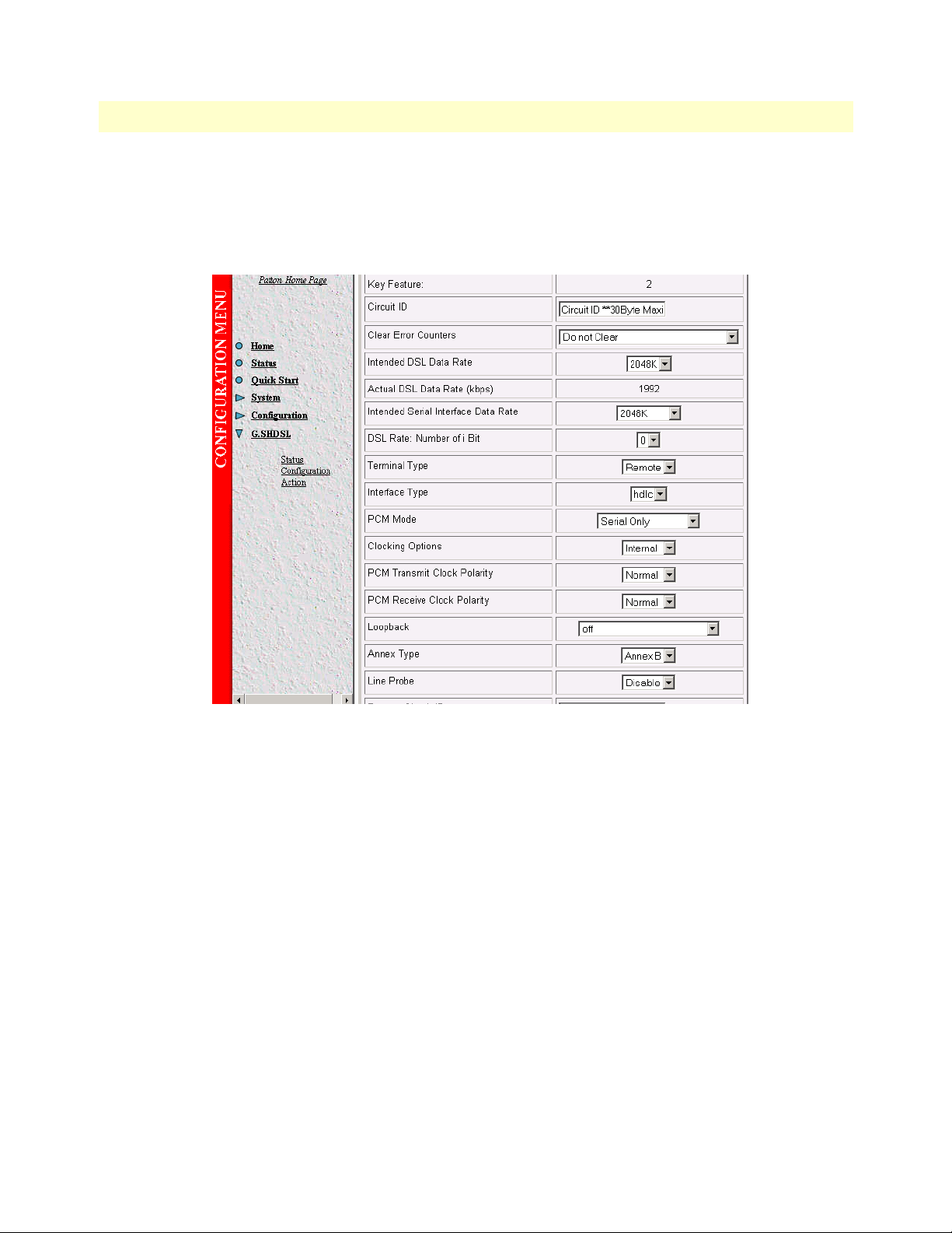
4 • Basic Application Configurations Model 3086 G.SHDSL Integrated Access Device User Guide
Web browser configuration
From the main menu in the 3086, select
screen below. For
the screen and click on the
Terminal Type
Configure
, select
GSHDSL > Configuration
Central
for 3086 A, and
button.
. Enter the selections as shown in the
Remote
for 3086 B. Then go to the bottom of
Circuit ID
User can enter up to 30 alphanumeric characters for circuit identification
Clear Error Counters
Selecting “Clear” will reset the error counters displayed in the “Status” screen.
Intended DSL Data Rate
This is the DSL line rate at which you wish to connect. In a point-to-point deployment, the unit designated as
“Central” will impose the line rate on the unit designated as “Remote”. The model 3086 offers nx64 kbps
speeds from 192 kbps to 4.6 Mbps.
Actual DSL Rate
This field displays the DSL rate connection; it displays the payload rate plus 8kbps automatically assigned to a
DSL management channel. For instance, if a DSL rate of 1984 kbps is selected in the “Intended DSL Data
Rate” window, the actual DSL data rate field will display 1992 kbps, this corresponds to 1984 kbps payload
plus 8 kbps management channel.
56 Using the 3086 as a simple modem (TDM data over DSL)
Page 57

Model 3086 G.SHDSL Integrated Access Device User Guide 4 • Basic Application Configurations
Intended Serial Interface Data Rate
Selects the data rate assigned to the serial port in nx64 kbps increments from 64 kbps to a maximum of
2.3
Mbps. The following conditions apply when configuring the 3086 serial port:
• When the 3086 is operating as a simple modem – serial port operation only, the data rate assigned to the
serial port must match the DSL rate (except when selecting 64 or 128kbps, DSL line rate at these speeds is
192kbps).
• When the 3086 transports serial and Ethernet traffic simultaneously, total data rate assigned to both Serial
and Ethernet must match the DSL rate.
• When using the 3086 for simultaneous Serial and Ethernet data transport, assign partial bandwidth to the
serial port only, the 3086 will automatically assign the remaining DSL bandwidth to the Ethernet port.
• When using the 3086 for simultaneous Serial and Ethernet data transport, timeslots (64kbps slots) carrying
serial data are placed in the upper slots of the DSL frame, while Ethernet data is placed in the lower DSL
frame timeslots.
• When the serial port is not used, set the “Intended Serial Interface” to “Not used”. The 3086 will automat-
ically assign all DSL bandwidth to the Ethernet port.
• When using a 3086 with T1/E1 interface, the “Intended Serial Interface” field must match the speed
selected for the T1/E1 port in the T1/E1 configuration menu.
DSL Rate: Number of i Bit
The i bit increments DSL speed by 8kbps in addition to the DSL rate selected in the “Intended DSL Data
Rate” window. Most applications use nx64kbps DSL speeds, leave this setting at “0”, unless your application
calls for a non-nx 64 speed. Selections for the I bit are 0 through 7 as follows:
• 0—No increment
• 1—Intended DSL data rate + 8 kbps
• 2—Intended DSL data rate + 16 kbps
• 3—Intended DSL data rate + 24 kbps
• 4—Intended DSL data rate + 32 kbps
• 5—Intended DSL data rate + 40 kbps
• 6—Intended DSL data rate + 48 kbps
• 7—Intended DSL data rate + 56 kbps
Terminal Type
Select between Remote and Central. Use the “Remote” setting for 3086s located at customer premises. Use
“Central” setting for units located at a Central Office or ISP.
Note
The unit set to “Central” will act as master and will impose DSL rate
on the unit set as “Remote”
Using the 3086 as a simple modem (TDM data over DSL) 57
Page 58

4 • Basic Application Configurations Model 3086 G.SHDSL Integrated Access Device User Guide
Interface Type
Selects between HDLC or ATM transports. This setting must match the transport selected in the “WAN connection” menu. When using the 3086 to transport serial data only, select HDLC transport.
PCM Mode
The PCM mode selection tells the Model 3086 whether the DSL link will carry Serial data (from serial port),
Ethernet data (from Ethernet port), or both Serial and Ethernet. Make sure to assign bandwidth to the serial
port in the “Intended Serial Interface Data Rate” when selecting “Serial” or “Serial and Ethernet” traffic.
Clocking Options
When using the serial port, the 3086 can transmit to the attached DTE using its internal clock, or using external clock from the DTE (this option is only available to units set for “Central”). Most applications use internal
clock.
PCM Transmit Polarity
When using long cables on the serial port side, it is possible that the clock and data arriving at the DTE may be
out of synchronization, causing data errors. Inverting the polarity of the transmit clock at the 3086 may solve
this problem. Use the “Normal” setting when using short serial cables (less than 6 feet or 1.8 meters).
PCM Receive Polarity
When using long cables on the serial port side, it is possible that the clock and data arriving at the 3086 may be
out of synchronization, causing data errors. Inverting the polarity of the receive clock at the 3086 may solve
this problem. Use the “Normal” setting when using short serial cables (less than 6 feet or 1.8 meters).
Loopback
The 3086 uses a series of loopbacks to test the serial, Ethernet, and DSL links, Refer to Chapter 9, “Diagnostics” on page 135 for more information.
Annex Type
Annex type refers to spectral compatibility between DSL and T1 or E1 signals. For North America and other
areas where T1 lines are used, select Annex A, for areas where E1 lines are used select Annex B.
Line Probe
Line probe is a tool used to determine maximum achievable rate when initially connecting 3086s to a copper
line of unknown quality. Set this feature to “Enable” on both 3086s at each end of the link. Once line probe
measurements have been completed set this feature to “Disabled”
Once you have completed your selections or changes, click on the
screen. Additionally, go to the
G.SHDSL > Action
link on the left side of the screen, and click
Configure
button at the bottom of the
action
to start the
DSL interface with the new settings.
TDM Plus Ethernet Traffic
The Model 3086 IAD can concurrently carry TDM data from the serial port (non-routed) and data from the
Ethernet port, both data streams are carried simultaneously over the DSL link.
Note
Data from the TDM port does not go through the routing core of the
model 3086, this data is sent unprocessed over the DSL link.
58 TDM Plus Ethernet Traffic
Page 59

Model 3086 G.SHDSL Integrated Access Device User Guide 4 • Basic Application Configurations
CLI configuration
Configuring the 3086 to transport TDM and IP data concurrently requires use of a Laptop or PC terminal.
When carrying IP data, the Model 3086 offers two WAN encapsulation methods: HDLC and ATM. In addi
tion, when connecting two LAN segments over DSL, the 3086 offers options for Routed or Bridged services.
The following example shows the configuration for connecting two LAN segments via DSL:
Selecting the DSL link speed
In this example a maximum DSL speed of 2.3Mbps (36 timeslots of 64 kbps each) will be selected, Using the
CLI enter the following command:
fi
gshdsl set dslrateTS 36 <enter>
Selecting PCM mode
The PCM mode selection tells the Model 3086 Whether the DSL link will carry TDM data (from TDM
port), Ethernet data (from Ethernet port), or both Serial and Ethernet.
-
In this example we will set the PCM mode for Serial and Ethernet data.
At the command prompt type:
fi
gshdsl set pcmmode EthernetandSerial <enter>
Assigning bandwidth to serial and Ethernet ports
In this example, half of the bandwidth 1.152 Mbps (18 TS) assigned to the serial port and the other half
1.152
Mbps (18 TS) assigned to the Ethernet port.
From the CLI command prompt type:
fi
gshdsl set serialTS 18 <enter>
Note
Enter the required bandwidth in number of 64kbps time slots for the
serial port, the 3086 automatically assigns the rest of the bandwidth
to the Ethernet ports. For example, if the total DSL bandwidth is
2.3
Mbps (36 TS), assigning 1.152 Mbps (18 TS) to the TDM port,
automatically assigns the rest of the DSL bandwidth (18 TS) for
Ethernet traffic.
When the 3086 carries both TDM and Ethernet traffic, it places serial data in the upper timeslots of the DSL
frame, and Ethernet timeslots to the lower portion of the DSL frame. In the example above, Ethernet data (18
TS) occupies timeslots from 1–18, while TDM data (18 TS) is carried in TS 19–36 of the DSL frame.
Central or Remote terminal (Master/Slave)
In a point-to-point deployment, one the two 3086s IAD must be set to Central (master), and the other to
Remote (slave).
TDM Plus Ethernet Traffic 59
Page 60

4 • Basic Application Configurations Model 3086 G.SHDSL Integrated Access Device User Guide
• For 3086 A at the prompt type
gshdsl set terminal central <enter>
• For 3086 B type
fi
gshdsl set terminal remote
Interface Type
Selects between HDLC and ATM transport. To select HDLC for both 3086 type:
fi
gshdsl set interface hdlc <enter>
Annex Type
Select between Annex A and Annex B.
To select Annex B type:
fi
gshdsl set ghsannex AnnexB
Web Browser Configuration
The web browser offers the easiest way to configure the 3086. Log on the 3086 web server (default username:
superuser, default password: superuser). From the main menu, click on the
G.SHDSL
option, select the “Con-
60 TDM Plus Ethernet Traffic
Page 61

Model 3086 G.SHDSL Integrated Access Device User Guide 4 • Basic Application Configurations
figuration option”. Use the drop down menus to enter the required configuration. Once all settings have been
selected, click on the
Configure
button at the bottom of the screen.
Circuit ID
User can enter up to 30 alphanumeric characters for circuit identification
Clear Error Counters
Selecting “Clear” will reset the error counters displayed in the “Status” screen.
Intended DSL Data Rate
This is the DSL line rate at which you wish to connect. In a point-to-point deployment, the unit designated as
“Central” will impose the line rate on the unit designated as “Remote”. The model 3086 offers nx64 kbps
speeds from 192 kbps to 4.6 Mbps.
Actual DSL Rate
This field displays the DSL rate connection; it displays the payload rate plus 8kbps automatically assigned to a
DSL management channel. For instance, if a DSL rate of 1984 kbps is selected in the “Intended DSL Data
Rate” window, the actual DSL data rate field will display 1992 kbps, this corresponds to 1984 kbps payload
plus 8 kbps management channel.
TDM Plus Ethernet Traffic 61
Page 62

4 • Basic Application Configurations Model 3086 G.SHDSL Integrated Access Device User Guide
Intended Serial Interface Data Rate
Selects the data rate assigned to the serial port in nx64 kbps increments from 64 kbps to a maximum of
2.3
Mbps. The following conditions apply when configuring the 3086 serial port:
• When the 3086 is operating as a simple modem – serial port operation only, the data rate assigned to the
serial port must match the DSL rate (except when selecting 64 or 128kbps, DSL line rate at these speeds is
192kbps).
• When the 3086 transports serial and Ethernet traffic simultaneously, total data rate assigned to both Serial
and Ethernet must match the DSL rate.
• When using the 3086 for simultaneous Serial and Ethernet data transport, assign partial bandwidth to the
serial port only, the 3086 will automatically assign the remaining DSL bandwidth to the Ethernet port.
• When using the 3086 for simultaneous Serial and Ethernet data transport, timeslots (64kbps slots) carrying
serial data are placed in the upper slots of the DSL frame, while Ethernet data is placed in the lower DSL
frame timeslots.
• When the serial port is not used, set the “Intended Serial Interface” to “Not used”. The 3086 will automat-
ically assign all DSL bandwidth to the Ethernet port.
• When using a 3086 with T1/E1 interface, the “Intended Serial Interface” field must match the speed
selected for the T1/E1 port in the T1/E1 configuration menu.
DSL Rate: Number of i Bit
The i bit increments DSL speed by 8kbps in addition to the DSL rate selected in the “Intended DSL Data
Rate” window. Most applications use nx64kbps DSL speeds, leave this setting at “0”, unless your application
calls for a non-nx 64 speed. Selections for the I bit are 0 through 7 as follows:
• 0—No increment
• 1—Intended DSL data rate + 8 kbps
• 2—Intended DSL data rate + 16 kbps
• 3—Intended DSL data rate + 24 kbps
• 4—Intended DSL data rate + 32 kbps
• 5—Intended DSL data rate + 40 kbps
• 6—Intended DSL data rate + 48 kbps
• 7—Intended DSL data rate + 56 kbps
Terminal Type
Select between Remote and Central. Use the “Remote” setting for 3086s located at customer premises. Use
“Central” setting for units located at a Central Office or ISP.
Note
The unit set to “Central” will act as master and will impose DSL rate
on the unit set as “Remote”
62 TDM Plus Ethernet Traffic
Page 63

Model 3086 G.SHDSL Integrated Access Device User Guide 4 • Basic Application Configurations
Interface Type
Selects between HDLC or ATM transports. This setting must match the transport selected in the “WAN connection” menu. When using the 3086 to transport serial data only, select HDLC transport.
PCM Mode
The PCM mode selection tells the Model 3086 whether the DSL link will carry Serial data (from serial port),
Ethernet data (from Ethernet port), or both Serial and Ethernet. Make sure to assign bandwidth to the serial
port in the “Intended Serial Interface Data Rate” when selecting “Serial” or “Serial and Ethernet” traffic.
Clocking Options
When using the serial port, the 3086 can transmit to the attached DTE using its internal clock, or using external clock from the DTE (this option is only available to units set for “Central”). Most applications use internal
clock.
PCM Transmit Polarity
When using long cables on the serial port side, it is possible that the clock and data arriving at the DTE may be
out of synchronization, causing data errors. Inverting the polarity of the transmit clock at the 3086 may solve
this problem. Use the “Normal” setting when using short serial cables (less than 6 feet or 1.8 meters).
PCM Receive Polarity
When using long cables on the serial port side, it is possible that the clock and data arriving at the 3086 may be
out of synchronization, causing data errors. Inverting the polarity of the receive clock at the 3086 may solve
this problem. Use the “Normal” setting when using short serial cables (less than 6 feet or 1.8 meters).
Loopback
The 3086 uses a series of loopbacks to test the serial, Ethernet, and DSL links, Refer to Chapter 9, “Diagnostics” on page 135 for more information.
Annex Type
Annex type refers to spectral compatibility between DSL and T1 or E1 signals. For North America and other
areas where T1 lines are used, select Annex A, for areas where E1 lines are used select Annex B.
Line Probe
Line probe is a tool used to determine maximum achievable rate when initially connecting 3086s to a copper
line of unknown quality. Set this feature to “Enable” on both 3086s at each end of the link. Once line probe
measurements have been completed set this feature to “Disabled”
Once you have completed your selections or changes, click on the
screen. Additionally, go to the
G.SHDSL > Action
link on the left side of the screen, and click
Configure
button at the bottom of the
action
to start the
DSL interface with the new settings.
This concludes the basic DSL configuration for Ethernet and serial ports.
If your application calls for Ethernet only, or Serial and Ethernet traffic you need to configure the Model 3086
Ethernet transport between HDLC or ATM encapsulation. In addition, select between bridged or routed con
figuration options, whichever meets your network needs. The following section steps through the various
application configurations options possible with the 3086.
-
TDM Plus Ethernet Traffic 63
Page 64

4 • Basic Application Configurations Model 3086 G.SHDSL Integrated Access Device User Guide
Using the 3086 in Routed or Bridged applications
Two stand-alone units directly connected
Ethernet extension (HDLC – PPPOH) Bridged
Model 3086 (Remote) Configuration Steps (PPPoH Bridged)
From the command line interface (CLI) via the RS-232 control port,
fi
ip list interfaces
One IP interface is called ip1 with an IP address of 192.168.1.1
Let’s change the IP address so it is in the same subnet as both PCs. For example, to 192.168.100.2
fi
ip set interface ip1 ipaddress 192.168.100.2 255.255.255.0
1. Now you can bring up the web-page management system on your browser by entering the IP address of
the 3086.
2. On the Menu, go to
Configuration
, then to
WAN Connections
. Delete the factory default WAN services already
defined.
Click on
Create a new service
in the main window, select
PPPoH_Bridged
and click on the
Configure
button.
3. In the Description field, enter the description you wish. In this example, it is called PPPoH Bridged.
64 Using the 3086 in Routed or Bridged applications
Page 65

Model 3086 G.SHDSL Integrated Access Device User Guide 4 • Basic Application Configurations
Verify the settings to be:
–Interface = 1
– LLC header mode = dialout
– LLC header mode = off
–HDLC header mode = on
– No authentication
–Leave User name and Password blank.
Click on
4. Go to
Apply
G.SHDSL
.
in the
Configuration Menu
, then the submenu
Configuration
.
Using the 3086 in Routed or Bridged applications 65
Page 66

4 • Basic Application Configurations Model 3086 G.SHDSL Integrated Access Device User Guide
Change Terminal Type to Central and Interface Type to hdlc. Click on the
In the Action submenu under G.SHDSL, change Action to
Return to Action, select
Start
and click on
Action
.
Deactivate
, then click on
Configure
button.
Action
.
Model 3086 (Central) Configuration Steps (PPPoH Bridged)
See the Web page images for the Remote Model 3086 configuration above.
From the command line interface (CLI) via the RS-232 control port,
fi
ip list interfaces
One IP interface is called ip1 with an IP address of 192.168.1.1
Change the IP address so it is in the same subnet as both PCs. For example, to 192.168.100.3
fi
ip set interface ip1 ipaddress 192.168.100.3 255.255.255.0
1. Now you can bring up the web-page management system on your browser by entering the IP address of
the 3086.
2. On the Menu, go to
Configuration
, then to
WAN Connections
. Delete the factory default WAN services already
defined.
Click on
In the
Create a new service
Description
field, enter the description you wish. In this example, it is called PPPoH Bridged.
in the main window, select
PPPoH_Bridged
and click on the
Configure
button.
Verify the settings to be:
–Interface = 1
– LLC header mode = dialout
66 Using the 3086 in Routed or Bridged applications
Page 67

Model 3086 G.SHDSL Integrated Access Device User Guide 4 • Basic Application Configurations
– LLC header mode = off
–HDLC header mode = on
– No authentication
– Leave User name and Password blank.
Click on
3. Go to
Apply
G.SHDSL
.
in the Configuration Menu, then the submenu
Leave Terminal Type as Remote.
Change Interface Type to
hdlc
. Click on the
Configure
In the Action submenu under G.SHDSL, change Action to
Return to Action, select
Start
and click on
Action
.
Network Extension (HDLC—PPPoH Routed)
button.
Configuration
Deactivate
.
, then click on
Action
.
Model 3086 (Remote) Configuration Steps (PPPoH Routed)
From the command line interface (CLI) via the RS-232 control port,
fi
ip list interfaces
One IP interface was called ip1 with an IP address of 192.168.1.1 Change it to an IP address which is in the
same subnet as the Desktop PC. For example, to 192.168.100.2. The default IP mask is 255.255.255.0.
fi
ip set interface ip1 ipaddress 192.168.100.2 255.255.255.0
Using the 3086 in Routed or Bridged applications 67
Page 68

4 • Basic Application Configurations Model 3086 G.SHDSL Integrated Access Device User Guide
1. Now you can bring up the web-page management system on your browser by entering the IP address of
the 3086.
Click on
is “hdlc.” If changed, then click on
Click on
2. On the Menu, go to
G.SHDSL
Action >
in the
Select
Configuration Menu > Configuration
deactivate
Configuration
Configure
for Action > Click on the
, then to
.
WAN Connections
> verify that Terminal Type is
Action
button.
Central
and Interface Type
Delete both default WAN services already defined.
Click on
Create a new service
in the main window, select
PPPoH_Routed
and click on the
Configure
In the Description field, enter the description you wish. In this example, it is called PPPoH Routed.
– Description: PPPoH Routed
–Interface: 1
– WAN IP address: 192.168.164.2
– LLC Header Mode: off
– HDLC Header Mode: ON
– No authentication
–Username: [blank]
– Password: [blank]
button.
68 Using the 3086 in Routed or Bridged applications
Page 69

Model 3086 G.SHDSL Integrated Access Device User Guide 4 • Basic Application Configurations
Click on
3. Go to
Configure
Configuration Menu > Configuration > WAN connections > Edit (for PPPoH Routed service) > Edit ‘IP Interface’ > Ipaddr:
.
the WAN IP Address, in this example = 192.168.164.2] > Click on
Change
[enter
.
Using the 3086 in Routed or Bridged applications 69
Page 70

4 • Basic Application Configurations Model 3086 G.SHDSL Integrated Access Device User Guide
4.
Configuration Menu > Configuration > IP Routes >
Click on
Create new Ip V4 Route
> Create the gateway to the remote
3086 by entering the WAN IP address of the remote 3086, in this example, enter 192.168.164.3 in the
Gateway field > OK
The other fields should be:
– Destination: 0.0.0.0
– Gateway: 192.168.164.3 [already configured in first part of step 4).]
– Mask: 0.0.0.0
–Cost: 1
– Interface: [blank]
70 Using the 3086 in Routed or Bridged applications
Page 71

Model 3086 G.SHDSL Integrated Access Device User Guide 4 • Basic Application Configurations
5. Go to G.SHDSL in the Configuration Menu, then the submenu Status. The Modem State should be
“deactivated.” (If not, go to the Action and change it to deactivate.)
Then in the Action submenu under G.SHDSL, change Action to Start, then click on
Action
.
Model 3086 (Central) Configuration Steps (PPPoH Routed)
See the web pages for the desktop above. Some parametric values are different although the process is the same.
From the command line interface (CLI) via the RS-232 control port,
fi
ip list interfaces
fi
ip clear routes
fi
pppoh clear transports
fi
ethernet add transport eth1 ethernet
One IP interface was called ip1 with an IP address of 192.168.1.1
Change the IP address so it is in the same subnet as the laptop PC. The laptop’s IP address is
192.168.172.229, so in this example, change the IP address of the 3086 to 192.168.172.3. The default IP
mask is 255.255.255.0.
fi
ip set interface ip1 ipaddress 192.168.172.3 255.255.255.0
1. Now you can bring up the web-page management system on your browser by entering the IP address of
the 3086.
Using the 3086 in Routed or Bridged applications 71
Page 72

4 • Basic Application Configurations Model 3086 G.SHDSL Integrated Access Device User Guide
Click on
is “hdlc.” If changed, then click on
Click on
2. On the Menu, go to
G.SHDSL
Action
in the
> Select
Configuration
Configuration Menu > Configuration >
deactivate
Configure
for Action > Click on the
, then to
.
WAN Connections
verify that Terminal Type is remote and Interface Type
Action
button.
.
Delete both default WAN services already defined.
Click on
Create a new service
in the main window, select
PPPoH_Routed
and click on the
Configure
In the Description field, enter the description you wish. In this example, it is called PPPoH Routed.
Description:PPPoH Routed
–Interface:1
– WAN IP address: 192.168.164.3
– LLC Header Mode:off
–HDLC Header Mode:ON
– No authentication
–Username:[blank]
–Password:[blank]
Click on
Configure
.
button.
3. Go to
4.
Configuration Menu > Configuration > WAN connections > Edit (for PPPoH Routed service) > Edit ‘IP Interface’ > Ipaddr:
the WAN IP Address, in this example = 192.168.164.3] > Click on
Configuration Menu > Configuration > IP Routes
> Click on
Create new Ip V4 Route
Change
.
> Create the gateway to the remote
3086 by entering the WAN IP address of the remote 3086, in this example, enter 192.168.164.2 in the
Gateway field > OK
The other fields should be:
– Destination:0.0.0.0
– Gateway:192.168.164.2 [already changed in the first part of step 5).]
– Mask:0.0.0.0
[enter
72 Using the 3086 in Routed or Bridged applications
Page 73

Model 3086 G.SHDSL Integrated Access Device User Guide 4 • Basic Application Configurations
–Cost:1
–Interface:[blank]
5. Go to
G.SHDSL
in the Configuration Menu, then the submenu
Status
. The Modem State should be “deacti-
vated.” (If not, go to the Action and change it to deactivate.)
Then in the Action submenu under G.SHDSL, change Action to Start, then click on
Action
.
DSLAM Connections with remote CPE units
Bridged application configurations to a DSLAM
Three bridged services are offered, RFC 1483 Bridged, PPPoA Bridged, and HDLC Bridged.
The configurations show a desktop on one end and a laptop on the other. The laptop and its Model 3086
would be replaced with a DSLAM.
RFC 1483 Bridged Configuration.
No additional IP addresses are needed other than the IP address chosen earlier. In fact, if you are configuring and
managing the model 3086 only from the CLI (Command Line Interface), an IP address is not needed at all. The
limitation of no IP address precludes the user from doing web management of the 3086 since management is
done via the Ethernet port.
As in the PPPoA Bridged application, both sides of the RFC 1483 bridged connection are on the same subnet.
DSLAM Connections with remote CPE units 73
Page 74

4 • Basic Application Configurations Model 3086 G.SHDSL Integrated Access Device User Guide
Model 3086 (Remote) Configuration Steps (RFC 1483 Bridged)
From the command line interface (CLI) via the RS-232 control port,
fi
ip list interfaces
One IP interface is called ip1 with an IP address of 192.168.1.1
Change the IP address so it is in the same subnet as both PCs. For example, to 192.168.100.2
fi
ip set interface ip1 ipaddress 192.168.100.2 255.255.255.0
1. Now you can bring up the web-page management system on your browser by entering the IP address of
the 3086.
2. On the Menu, go to Configuration, then to WAN Connections. Delete the factory default WAN services
already defined.
Click on
Create a new service
in the main window, select
RFC_1483_Bridged
and click on the
Configure
In the Description field, enter the description you wish. In this example, it is called RFC 1483 B.
Leave VCI as 35 and Encapsulation Method as LLC/SNAP. Then click on
3. Go to
G.SHDSL
in the Configuration Menu, then the submenu
Configuration
Apply
.
.
button.
74 DSLAM Connections with remote CPE units
Page 75

Model 3086 G.SHDSL Integrated Access Device User Guide 4 • Basic Application Configurations
Change Terminal Type to Remote and Interface Type to atm. Click on the
In the Action submenu under G.SHDSL, change Action to
Return to Action, select
Start
and click on
Action
.
Deactivate
Configure
button.
, then click on Action.
Model 3086 (Central) Configuration Steps (RFC 1483 Bridged)
Although the some parametric values may vary from the desktop’s Model 3086, the process is identical.
From the command line interface (CLI) via the RS-232 control port,
fi
ip list interfaces
One IP interface is called ip1 with an IP address of 192.168.1.1
Change the IP address so it is in the same subnet as both PCs. For example, to 192.168.100.3
fi
ip set interface ip1 ipaddress 192.168.100.3 255.255.255.0
1. Now you can bring up the web-page management system on your browser by entering the IP address of
the 3086.
2. On the Menu, go to Configuration, then to WAN Connections. Delete the factory default WAN services
already defined.
Click on
Create a new service
in the main window, select
RFC_1483_Bridged
and click on the
Configure
button.
In the Description field, enter the description you wish. In this example, it is called RFC 1483 B.
DSLAM Connections with remote CPE units 75
Page 76

4 • Basic Application Configurations Model 3086 G.SHDSL Integrated Access Device User Guide
Leave VCI as 35 and Encapsulation Method as LLC/SNAP. Then click on
Apply
3. Go to G.SHDSL in the Configuration Menu, then the submenu Configuration.
Leave Terminal Type as Remote, but change Interface Type to atm. Click on the
In the Action submenu under G.SHDSL, change Action to
Return to Action, select
Start
and click on
Action
.
Deactivate
, then click on
.
Configure
Action
button.
.
PPPoH Bridged Configuration
Model 3086 (Remote) Configuration Steps (PPPoH Bridged)
From the command line interface (CLI) via the RS-232 control port,
fi
ip list interfaces
One IP interface is called ip1 with an IP address of 192.168.1.1 Change the IP address so it is in the same subnet as both PCs. For example, to 192.168.100.2
fi
ip set interface ip1 ipaddress 192.168.100.2 255.255.255.0
1. Now you can bring up the web-page management system on your browser by entering the IP address of
the 3086.
2. On the Menu, go to
Configuration
, then to WAN Connections. Delete the factory default WAN services
already defined.
76 DSLAM Connections with remote CPE units
Page 77

Model 3086 G.SHDSL Integrated Access Device User Guide 4 • Basic Application Configurations
Click on
Create a new service
in the main window, select
PPPoH_Bridged
and click on the
Configure
button.
In the Description field, enter the description you wish. In this example, it is called PPPoH Bridged.
–Interface = 1
– LLC header mode = dialout
– LLC header mode = off
–HDLC header mode = on
– No authenticaion
– Leave User name and Password blank.
–Click on
3. Go to
–Change Terminal Type to Remote and Interface Type to hdlc. Click on the
– In the Action submenu under G.SHDSL, change Action to Deactivate, then click on
– Return to Action, select
DSLAM Connections with remote CPE units 77
Apply
.
G.SHDSL
in the Configuration Menu, then the submenu
Start
and click on
Action
Configuration
.
Configure
button.
Action
.
.
Page 78

4 • Basic Application Configurations Model 3086 G.SHDSL Integrated Access Device User Guide
Model 3086 (Central) Configuration Steps (PPPoH Bridged)
From the command line interface (CLI) via the RS-232 control port,
fi
ip list interfaces
One IP interface is called ip1 with an IP address of 192.168.1.1
Change the IP address so it is in the same subnet as both PCs. For example, to 192.168.100.3
fi
ip set interface ip1 ipaddress 192.168.100.3 255.255.255.0
1. Now you can bring up the web-page management system on your browser by entering the IP address of
the 3086.
2. On the Menu, go to Configuration, then to WAN Connections. Delete the factory default WAN services
already defined.
Click on
Create a new service
in the main window, select
PPPoH_Bridged
and click on the
Configure
In the Description field, enter the description you wish. In this example, it is called PPPoH Bridged.
–Interface = 1
– LLC header mode = dialout
– LLC header mode = off
–HDLC header mode = on
– No authenticaion
– Leave User name and Password blank.
Click on
Apply
.
3. Go to G.SHDSL in the Configuration Menu, then the submenu Configuration.
Leave Terminal Type as Central.
Change Interface Type to hdlc. Click on the Configure button.
In the Action submenu under G.SHDSL, change Action to Deactivate, then click on
Return to Action, select Start and click on
Action
.
Action
button.
.
78 DSLAM Connections with remote CPE units
Page 79

Model 3086 G.SHDSL Integrated Access Device User Guide 4 • Basic Application Configurations
PPPoA Bridged (RFC 2364) Configuration
The user data for transmission is in the form of IP packets but encapsulated in a PPP packet, transmitted and
received through a PPP session to the connection. The PPP packets are encapsulated according to RFC 2364 for
transmission over the ATM link. The packets are de-encapsulated on the receive side so that the IP data can be
delivered to the end user.
Model 3086 (Remote) Configuration Steps (PPPoA Bridged)
From the command line interface (CLI) via the RS-232 control port,
fi
ip list interfaces
One IP interface is called ip1 with an IP address of 192.168.1.1
Change the IP address so it is in the same subnet as both PCs. For example, to 192.168.100.2
fi
ip set interface ip1 ipaddress 192.168.100.2 255.255.255.0
1. Now you can bring up the web-page management system on your browser by entering the IP address of
the 3086.
2. On the Menu, go to Configuration, then to WAN Connections. Delete the factory default WAN services
already defined.
Click on
Create a new service
in the main window, select
PPPoA_Bridged
and click on the
Configure
button.
In the Description field, enter the description you wish. In this example, it is called PPPoA Bridged.
DSLAM Connections with remote CPE units 79
Page 80

4 • Basic Application Configurations Model 3086 G.SHDSL Integrated Access Device User Guide
–VPI = 0
– VCI = 300
– LLC header mode = off
–HDLC header mode = off
– No authentication
– Leave User name and Password blank.
Click on
Apply
.
3. Go to G.SHDSL in the Configuration Menu, then the submenu Configuration.
Change Terminal Type to Remote and Interface Type to atm. Click on the
In the Action submenu under G.SHDSL, change Action to
Return to Action, select
Start
and click on
Action
.
Deactivate
Configure
, then click on
button.
Action
.
Model 3086 (Central)Configuration Steps (PPPoA Bridged)
From the command line interface (CLI) via the RS-232 control port,
fi
ip list interfaces
One IP interface is called ip1 with an IP address of 192.168.1.1
Change the IP address so it is in the same subnet as both PCs. For example, to 192.168.100.3
fi
ip set interface ip1 ipaddress 192.168.100.3 255.255.255.0
1. Now you can bring up the web-page management system on your browser by entering the IP address of
the 3086.
2. On the Menu, go to Configuration, then to WAN Connections. Delete the factory default WAN services
already defined.
Click on
Create a new service
in the main window, select
PPPoA_Bridged
and click on the
Configure
button.
In the Description field, enter the description you wish. In this example, it is called PPPoA Bridged.
–VPI = 0
– VCI = 300
– LLC header mode = off
–HDLC header mode = off
80 DSLAM Connections with remote CPE units
Page 81

Model 3086 G.SHDSL Integrated Access Device User Guide 4 • Basic Application Configurations
– No authentication
– Leave User name and Password blank.
Click on
Apply
.
3. Go to G.SHDSL in the Configuration Menu, then the submenu Configuration.
Leave Terminal Type as Central.
Change Interface Type to atm. Click on the
In the Action submenu under G.SHDSL, change Action to Deactivate, then click on
Return to Action, select
Start
and click on
Configure
Action
button.
Action
.
Routed application configurations to a DSLAM
Five routed WAN services are offered, RFC 1483, PPPoH, IPoA, PPPoA, and PPPoE Routed.
.
RFC 1483 Routed
RFC 1483 provides the simplest method of connecting end stations over an ATM network. User data in the
form of Ethernet packets is encapsulated into AAL-5 PDUs for transport over ATM. RFC 1483 provides no
authentication and configuration that would be provided by PPP.
Model 3086 (Remote) Configuration Steps (RFC 1483 Routed)
From the command line interface (CLI) via the RS-232 control port,
fi
ip list interfaces
One IP interface was called ip1 with an IP address of 192.168.1.1 Change it to an IP address which is in the
same subnet as the Desktop PC. For example, to 192.168.100.2. The default IP mask is 255.255.255.0.
fi
ip set interface ip1 ipaddress 192.168.100.2 255.255.255.0
DSLAM Connections with remote CPE units 81
Page 82

4 • Basic Application Configurations Model 3086 G.SHDSL Integrated Access Device User Guide
1. Now you can bring up the web-page management system on your browser by entering the IP address of
the 3086.
Click on G.SHDSL in the Configuration Menu > Configuration > verify that Terminal Type is Central
and Interface Type is atm. If changed, then click on
Configure
.
Click on Action > Select deactivate for Action > Click on the Action button.
2. On the Menu, go to Configuration, then to WAN Connections.
Delete both default WAN services already defined.
Click on
Create a new service
in the main window, select
RFC 1483 Routed
and click on the
Configure
button.
82 DSLAM Connections with remote CPE units
Page 83

Model 3086 G.SHDSL Integrated Access Device User Guide 4 • Basic Application Configurations
In the Description field, enter the description you wish. In this example, it is called RFC 1483 Routed.
Change the configuration parameters to match the following.
Description:RFC 1483 Routed
–VPI:0
–VCI:35
– Encapsulation Method: LLC/SNAP
– WAN IP Address:192.168.164.2
Click on
Configure
.
3. Configuration Menu > Configuration > IP Routes > Click on Create new Ip V4 Route > Create the gateway to the remote 3086 by entering the WAN IP address of the remote 3086, in this example, enter
192.168.164.3 in the Gateway field > OK
DSLAM Connections with remote CPE units 83
Page 84

4 • Basic Application Configurations Model 3086 G.SHDSL Integrated Access Device User Guide
The other fields should be:
– Destination:0.0.0.0
– Gateway:192.168.164.3
– Mask:0.0.0.0
–Cost:1
–Interface:[blank]
4. Go to G.SHDSL in the Configuration Menu, then the submenu Status. The Modem State should be
“deactivated.” (If not, go to the Action and change it to deactivate.)
Then in the Action submenu under G.SHDSL, change Action to
Start
, then click on
Action
.
Model 3086 (Central) Configuration Steps (RFC 1483 Routed)
From the command line interface (CLI) via the RS-232 control port,
fi
ip list interfaces
fi
pppoh clear transports
One IP interface was called ip1 with an IP address of 192.168.1.1
84 DSLAM Connections with remote CPE units
Page 85

Model 3086 G.SHDSL Integrated Access Device User Guide 4 • Basic Application Configurations
Change the IP address so it is in the same subnet as the laptop PC. The laptop’s IP address is
192.168.172.229, so in this example, change the IP address of the 3086 to 192.168.172.3. The default IP
mask is 255.255.255.0.
fi
ip set interface ip1 ipaddress 192.168.100.2 255.255.255.0
1. Now you can bring up the web-page management system on your browser by entering the IP address of
the 3086.
Click on G.SHDSL in the Configuration Menu > Configuration > verify that Terminal Type is Remote and
Interface Type is atm. If changed, then click on
Configure
.
DSLAM Connections with remote CPE units 85
Page 86

4 • Basic Application Configurations Model 3086 G.SHDSL Integrated Access Device User Guide
Click on Action > Select deactivate for Action > Click on the Action button.
2. On the Menu, go to Configuration, then to WAN Connections.
Delete both default WAN services already defined.
Click on
Create a new service
in the main window, select
RFC 1483 Routed
and click on the
Configure
button.
In the Description field, enter the description you wish. In this example, it is called RFC 1483 Routed.
Description:RFC 1483 Routed
–VPI:0
–VCI:35
– Encapsulation Method: LLC/SNAP
– WAN IP Address:192.168.164.3
Click on
Configure
.
86 DSLAM Connections with remote CPE units
Page 87

Model 3086 G.SHDSL Integrated Access Device User Guide 4 • Basic Application Configurations
3. Configuration Menu > Configuration > IP Routes > Click on Create new Ip V4 Route > Create the gateway to the remote 3086 by entering the WAN IP address of the remote 3086, in this example, enter
192.168.164.2 in the Gateway field > OK
The other fields should be:
– Destination:0.0.0.0
– Gateway:192.168.164.2
– Mask:0.0.0.0
–Cost:1
–Interface:[blank]
DSLAM Connections with remote CPE units 87
Page 88

4 • Basic Application Configurations Model 3086 G.SHDSL Integrated Access Device User Guide
4. Go to G.SHDSL in the Configuration Menu, then the submenu Status. The Modem State should be
“deactivated.” (If not, go to the Action and change it to deactivate.)
Then in the Action submenu under G.SHDSL, change Action to Start, then click on Action.
The modems should link up within 30 seconds or so and the link is ready for communication.
PPPoH Routed
Model 3086 (Remote) Configuration Steps (PPPoH Routed)
From the command line interface (CLI) via the RS-232 control port,
fi
ip list interfaces
fi
ip clear routes
fi
pppoh clear transports
88 DSLAM Connections with remote CPE units
Page 89

Model 3086 G.SHDSL Integrated Access Device User Guide 4 • Basic Application Configurations
One IP interface was called ip1 with an IP address of 192.168.1.1 Change it to an IP address which is in the
same subnet as the Desktop PC. For example, to 192.168.100.2. The default IP mask is 255.255.255.0.
fi
ip set interface ip1 ipaddress 192.168.100.2 255.255.255.0
1. Now you can bring up the web-page management system on your browser by entering the IP address of
the 3086.
Click on G.SHDSL in the Configuration Menu > Configuration > verify that Terminal Type is Central
and Interface Type is hdlc. If changed, then click on
Configure
.
Click on Action > Select deactivate for Action > Click on the Action button.
2. On the Menu, go to Configuration, then to WAN Connections
Delete both default WAN services already defined.
Click on
Create a new service
in the main window, select
PPPoH_Routed
and click on the
Configure
In the Description field, enter the description you wish. In this example, it is called PPPoH Routed.
– Description:PPPoH Routed
–Interface:1
– WAN IP address: 192.168.164.2
– LLC Header Mode:off
button.
– HDLC Header Mode:ON
– No authentication
DSLAM Connections with remote CPE units 89
Page 90

4 • Basic Application Configurations Model 3086 G.SHDSL Integrated Access Device User Guide
–Username:[blank]
– Password:[blank]
Click on
Configure
.
3. Go to Configuration Menu > Configuration > WAN connections > Edit (for PPPoH Routed service) >
Edit ‘IP Interface’ > Ipaddr: [enter the WAN IP Address, in this example = 192.168.164.2] > Click on
Change.
90 DSLAM Connections with remote CPE units
Page 91
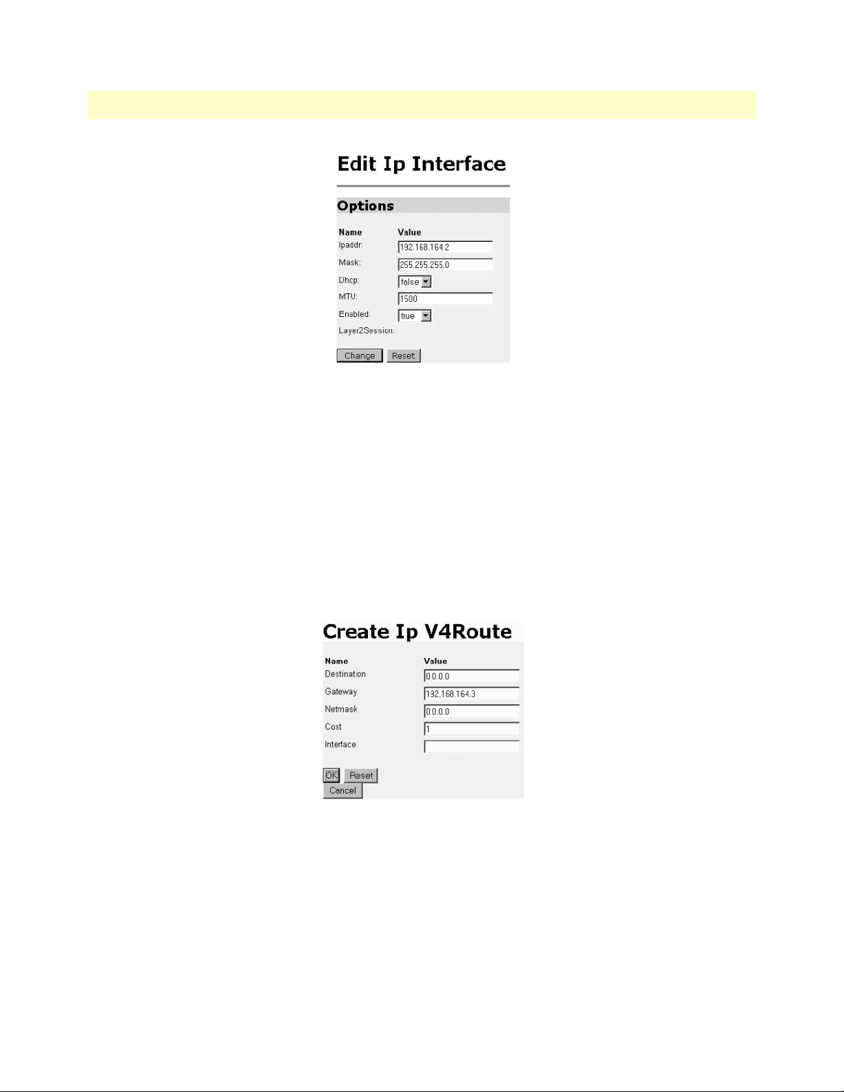
Model 3086 G.SHDSL Integrated Access Device User Guide 4 • Basic Application Configurations
4. Configuration Menu > Configuration > IP Routes > Click on Create new Ip V4 Route > Create the gateway to the remote 3086 by entering the WAN IP address of the remote 3086, in this example, enter
192.168.164.3 in the Gateway field > OK
The other fields should be:
Destination:0.0.0.0
Gateway:192.168.164.3 [already configured in first part of step 5).]
Mask:0.0.0.0
Cost:1
Interface:[blank]
DSLAM Connections with remote CPE units 91
Page 92

4 • Basic Application Configurations Model 3086 G.SHDSL Integrated Access Device User Guide
5. Go to G.SHDSL in the Configuration Menu, then the submenu Status. The Modem State should be
“deactivated.” (If not, go to the Action and change it to deactivate.)
Then in the Action submenu under G.SHDSL, change Action to Start, then click on
Action
.
Model 3086 (Central) Configuration Steps (PPPoH Routed)
From the command line interface (CLI) via the RS-232 control port,
fi
ip list interfaces
fi
pppoh clear transports
One IP interface was called ip1 with an IP address of 192.168.1.1
Change the IP address so it is in the same subnet as the laptop PC. The laptop’s IP address is
192.168.172.229, so in this example, change the IP address of the 3086 to 192.168.172.3. The default IP
mask is 255.255.255.0.
fi
ip set interface ip1 ipaddress 192.168.172.3 255.255.255.0
92 DSLAM Connections with remote CPE units
Page 93

Model 3086 G.SHDSL Integrated Access Device User Guide 4 • Basic Application Configurations
1. Now you can bring up the web-page management system on your browser by entering the IP address of
the 3086.
Click on G.SHDSL in the Configuration Menu > Configuration > verify that Terminal Type is Central
and Interface Type is hdlc. If changed, then click on
Configure
.
Click on Action > Select deactivate for Action > Click on the
Action
button.
2. On the Menu, go to Configuration, then to WAN Connections.
Delete both default WAN services already defined.
Click on
Create a new service
in the main window, select
PPPoH_Routed
and click on the
Configure
In the Description field, enter the description you wish. In this example, it is called PPPoH Routed.
– Description:PPPoH Routed
–Interface:1
– WAN IP address: 192.168.164.3
– LLC Header Mode:off
– HDLC Header Mode:ON
– No authentication
–Username:[blank]
– Password:[blank]
Click on
Configure
.
button.
DSLAM Connections with remote CPE units 93
Page 94

4 • Basic Application Configurations Model 3086 G.SHDSL Integrated Access Device User Guide
3. Go to Configuration Menu > Configuration > WAN connections > Edit (for PPPoH Routed service) >
Edit ‘IP Interface’ > Ipaddr: [enter the WAN IP Address, in this example = 192.168.164.3] > Click on
Change.
4. Configuration Menu > Configuration > IP Routes > Click on Create new Ip V4 Route > Create the gateway to the remote 3086 by entering the WAN IP address of the remote 3086, in this example, enter
192.168.164.2 in the Gateway field > OK
The other fields should be:
– Destination:0.0.0.0
– Gateway:192.168.164.2 [already changed in the first part of step 5).]
– Mask:0.0.0.0
–Cost:1
–Interface:[blank]
5. Go to G.SHDSL in the Configuration Menu, then the submenu Status. The Modem State should be
“deactivated.” (If not, go to the Action and change it to deactivate.)
Then in the Action submenu under G.SHDSL, change Action to Start, then click on
Action
.
94 DSLAM Connections with remote CPE units
Page 95

Model 3086 G.SHDSL Integrated Access Device User Guide 4 • Basic Application Configurations
PPPoA Routed (RFC 2364)
This routed application is very similar to the PPPoA Bridged application. The user data for transmission is in
the form of IP packets but encapsulated in a PPP packet, transmitted and received through a PPP session to the
connection. The PPP packets are encapsulated according to RFC 2364 for transmission over the ATM link.
The packets are de-encapsulated on the receive side so that the IP data can be delivered to the end user.
The Central (Model 3086) end functions as a local ISP which will authenticate the Remote user (Model
3086). The CPE side, with Remote and 3086-A, may represent a home PC which is connecting to a central
-
ized PPP server (Local and 3086—B).
Since this is a routed application, there are differences to be noted. Referring to the application diagram, three
unique subnets exist. The Ethernet LAN on the 3086 and Remote side, the Ethernet LAN on the 3086 and
Central side, and lastly, the subnet of the ATM’s PVC link between the two modems, 3086-A and 3086-B.
The 3086-B and Local end (the Central side) may also be a DSLAM.
Model 3086 (Remote—Client) Configuration Steps (PPPoA Routed)
1. From the command line interface (CLI) via the RS-232 control port,
fi
ip list interfaces
One IP interface was called ip1 with an IP address of 192.168.1.1 Change it to an IP address which is in
the same subnet as the Desktop PC. For example, to 192.168.100.2. The default IP mask is
255.255.255.0.
fi
ip set interface ip1 ipaddress 192.168.100.2 255.255.255.0
DSLAM Connections with remote CPE units 95
Page 96

4 • Basic Application Configurations Model 3086 G.SHDSL Integrated Access Device User Guide
Now you can bring up the web-page management system on your browser by entering the IP address of
the 3086.
Click on G.SHDSL in the Configuration Menu > Configuration > verify that Terminal Type is Central
and Interface Type is atm. If changed, then click on
Configure
.
Click on Action > Select deactivate for Action > Click on the
Action
button.
2. On the Menu, go to Configuration, then to WAN Connections
Delete both default WAN services already defined.
Click on
Create a new service
in the main window, select
PPPoA Routed
and click on the
Configure
button.
In the Description field, enter the description you wish. In this example, it is called PPPoA Routed.
Change the configuration parameters to match the following.
– Description:PPPoA Routed
–VPI:0
– VCI:800
– WAN IP Address:0.0.0.0
– LLC Header Mode:off
–HDLC Header Mode:off
–CHAP
– User Name:fred
– Passwood:fredspass
Click on
96 DSLAM Connections with remote CPE units
Configure
.
Page 97

Model 3086 G.SHDSL Integrated Access Device User Guide 4 • Basic Application Configurations
3. In the Configuration Menu, click on Configuration then > WAN Connections > Edit (for the WAN Service ppp1) > Edit ‘PPP’ and verify or change the following parameters on the Edit PPP webpage.
–Server:false
–Create Route:true
– Specific Route:false
– Subnet Mask:0.0.0.0
– Route Mask:0.0.0.0
–Hdlc:false
–LLC:false
–Lcp Max Configure:10
–Lcp Max Failure:5
–Lcp Max Terminate:2
–Dialin Auth:none
– Dialout Username:fred
– Dialout Password:fredspass
– Confirmation Password:fredspass
– Dialout Auth:chap
– Interface ID:1
– Remote IP:192.168.164.2
– Local IP:0.0.0.0
– Magic Number:0
–MRU:0
– IP Addr from IPCP:true
DSLAM Connections with remote CPE units 97
Page 98

4 • Basic Application Configurations Model 3086 G.SHDSL Integrated Access Device User Guide
– Discover Primary DNS:true
–Discover Secondary DNS:true
– Give DNS to Relay:true
– Give DNS to Client:true
– Remote DNS:0.0.0.0
– Remote Secondary:0.0.0.0
–LCP Echo Every:10
–Auto Connect:false
–Idle Timeout:0
–Termination:true
Change
Click on
button.
4. Click on Edit ‘ATM Channel.’
Verify the Options to match the following. (Change if necessary.)
–Tx Vci:800
–Tx Vpi:0
– Rx Vci:800
–Rx Vpi:0
– Peak Cell Rate:2000
–Burst Tolerance:0
–MCR:0
–MBS:0
– Sustainable Cell Rate:0
98 DSLAM Connections with remote CPE units
Page 99
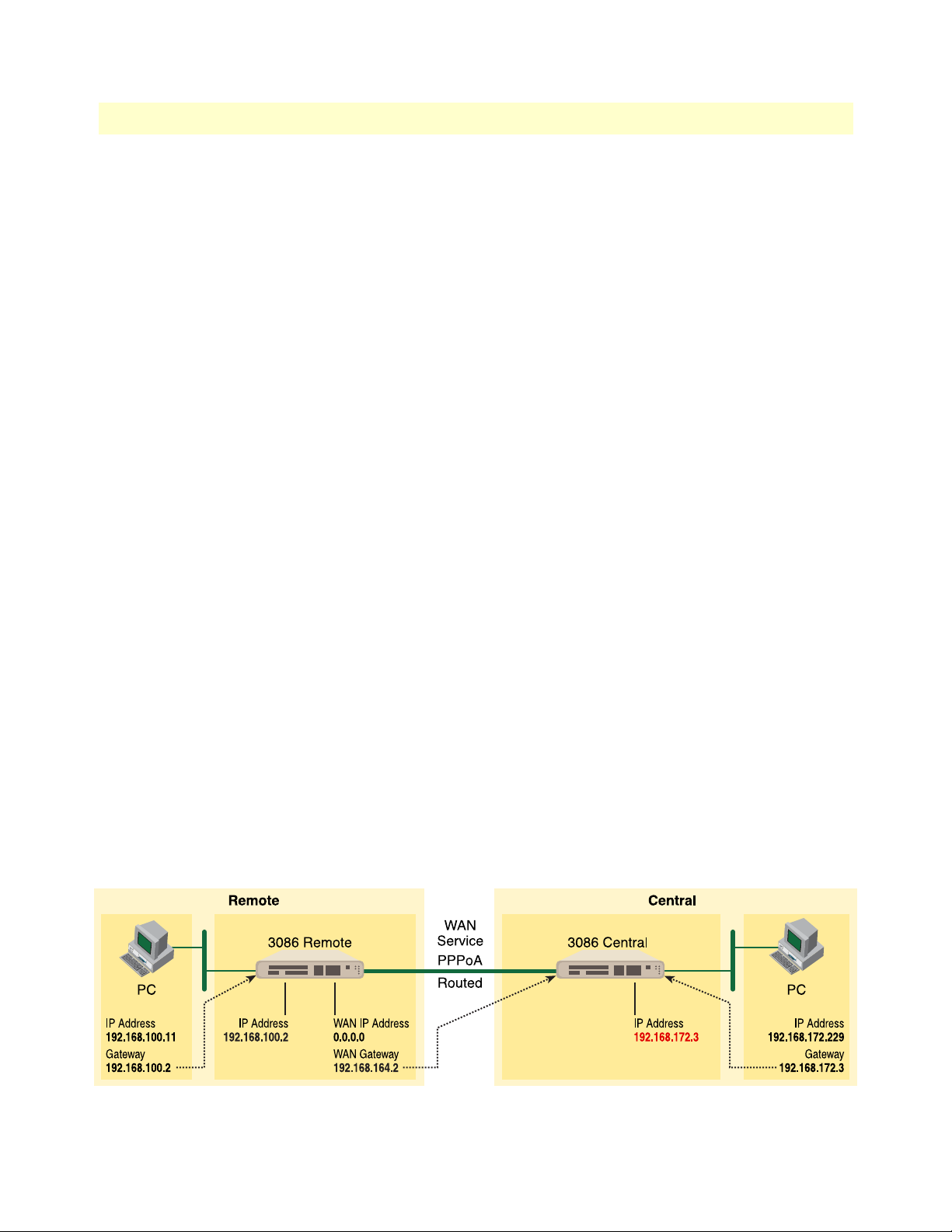
Model 3086 G.SHDSL Integrated Access Device User Guide 4 • Basic Application Configurations
–Class:UBR
–Port:atm
Change
Click on the
button if changes were made.
5. Click on Edit ‘IP Interface.’
Verify or change if necessary the following Options parameters.
– Ipaddr:0.0.0.0
– Mask:0.0.0.0
–Dhcp:false
–MTU:1500
–Enabled:true
Change
Click on the
button if changes were made.
6. There is no gateway created in the IP routes submenu. Upon connecting, the server will provide this information while setting up the PPP connection.
7. Go to G.SHDSL in the Configuration Menu, then the submenu Status. The Modem State should be
“deactivated.” (If not, go to the Action and change it to deactivate.)
Then in the Action submenu under G.SHDSL, change Action to Start, then click on
Action
.
Model 3086 (Central—Server) Configuration Steps (PPPoA Routed)
1. From the command line interface (CLI) via the RS-232 control port,
fi
ip list interfaces
One IP interface was called ip1 with an IP address of 192.168.1.1 Change it to an IP address which is in
the same subnet as the Desktop PC. For example, to 192.168.172.3. The default IP mask is
255.255.255.0.
fi
ip set interface ip1 ipaddress 192.168.172.3 255.255.255.0
DSLAM Connections with remote CPE units 99
Page 100

4 • Basic Application Configurations Model 3086 G.SHDSL Integrated Access Device User Guide
Now you can bring up the web-page management system on your browser by entering the IP address of
the 3086.
Click on G.SHDSL in the Configuration Menu> Configuration > verify that Terminal Type is Central and
Interface Type is atm. If changed, then click on
Configure
.
Click on Action > Select deactivate for Action > Click on the
Action
2. On the Menu, go to Configuration, then to WAN Connections
Delete both default WAN services already defined.
Click on
Create a new service
in the main window, select
PPPoA Routed
and click on the
button.
Configure
button.
100 DSLAM Connections with remote CPE units
 Loading...