

Page 1

B
DIGITAL DATA SERVICE MULTIPLEXER
Doc #: 138001UA
Part #: 07M3046-A
3046/V24 & 3046/V35
(CTS DDS-MUX)
INSTALLATION AND OPERATIONS MANUAL
May 24, 2000
An ISO-9001
Certified Company
Copyright© 2000 Patton Electronics Co., All Rights Reserved
Page 2

B
DIGITAL DATA SERVICE MULTIPLEXER
Doc #: 138001UA
Part #: 07M3046-A
3046/V24 & 3046/V35
(CTS DDS-MUX)
INSTALLATION AND OPERATIONS MANUAL
An ISO-9001
Certified Company
Copyright© 2000 Patton Electronics Co., All Rights Reserved
Page 3

PATTON ELECTRONICS CO.INSTALLATION AND OPERATIONS MANUAL3046
138001UA
PROPRIETARY NOTICE
The information contained herein is proprietary and confidential to Patton Electronics Co. Any reproduction or
redistribution of this publication, in whole or in part, is expressly prohibited unless written authorization is given by Patton
Electronics Co.
WARRANTY NOTICE
WARRANTIES: Patton Electronics Co. (hereafter referred to as Patton) warrants that its equipment is free from any
defects in materials and workmanship. The warranty period shall be two years from the date of shipment of equipment.
Patton’s sole obligation under its warranty is limited to the repair or replacement of the defective equipment, provided it
is returned to Patton, transportation prepaid, within a reasonable period. This warranty will not extend to equipment
subjected to accident, misuse, alterations or repair not made by Patton or authorized by Patton in writing.
PUBLICATION NOTICE
This manual has been compiled and checked for accuracy. The information in this manual does not constitute a
warranty of performance. Patton reserves the right to revise this publication and make changes from time to time in the
content thereof. Patton assumes no liability for losses incurred as a result of out-of-date or incorrect information
contained in this manual.
RADIO AND TV INTERFERENCE
The Patton MSDs generate and use radio frequency energy, and if not installed and used properly—that is, in strict
accordance with the manufacturer’s instructions—may cause interference to radio and television reception. The Patton
MSDs have been tested and found to comply with the limits for Class A computing devices in accordance with the
specifications in Subpart J of Part 15 of FCC rules, which are designed to provide reasonable protection from such
interference in a commercial installation. However, there is no guarantee that interference will not occur in a particular
installation. If the Patton MSDs do cause interference to radio or television reception, which can be determined by
disconnecting the cables, the user is encouraged to try to correct the interference by one or more of the following
measures: moving the computing equipment away from the receiver, re-orienting the receiving antenna, and/or plugging
the receiving equipment into a different AC outlet (such that the computing equipment and receiver are on different
branches).
CE NOTICE
The CE symbol on your Patton Electronics equipment indicates that it is in compliance with the electromagnetic
Compatibility (EMC) directive and the Low Voltage Directive (LVD) of the European Union (EU). A Certificate of
Compliance is available by contacting Technical Support.
SERVICE
All warranty and non-warranty repairs must be returned freight prepaid and insured to Patton Electronics. All returns
must have a Return Materials Authorization number on the outside of the shipping container. This number may be
obtained from Patton Electronics Technical Support at:
tel: (301) 975-1007;
email: support@patton.com;
or, www: http://www.patton.com.
NOTE: Packages received without an RMA number will not be accepted.
Patton Electronics’ technical staff is also available to answer any questions that might arise concerning the installation or
use of your Patton MSDs. Technical Support hours: 8AM to 5PM EST, Monday through Friday.
Copyright© 2000 Patton Electronics Co., All Rights Reserved
i
i
Page 4

138001UA
This Page Left Blank
INSTALLATION AND OPERATIONS MANUALPATTON ELECTRONICS CO. 3046
ii
ii
Page 5

PATTON ELECTRONICS CO.INSTALLATION AND OPERATIONS MANUAL3046
138001UA
Contents
CHAPTER 1 - OPERATION
Channel Selection Modes ................................................................................................................. 1-1
Channel Clocking .............................................................................................................................. 1-1
Channel Interface .............................................................................................................................. 1-1
Front Panel LEDs..............................................................................................................................1-2
Front Panel LCD and Push Buttons .................................................................................................1-2
Loopback Selection........................................................................................................................... 1-2
Power Supply .................................................................................................................................... 1-2
Installation Options............................................................................................................................ 1-2
CHAPTER 2 - SETUP AND INSTALLATION
Power Connection .............................................................................................................................2-1
Factory Configuration Switch Settings ............................................................................................. 2-1
Disassembly ...................................................................................................................................... 2-1
Installation ......................................................................................................................................... 2-2
Push Buttons ..................................................................................................................................... 2-2
LCD SYSTEM STATUS Display....................................................................................................... 2-3
Composite Link Configuration ........................................................................................................... 2-3
Speed .......................................................................................................................................... 2-4
Mode ............................................................................................................................................ 2-5
Remote Digital Loopback ............................................................................................................ 2- 6
Channel Configuration ......................................................................................................................2-7
Speed ..........................................................................................................................................2-7
Mode............................................................................................................................................2-8
Character Length ........................................................................................................................ 2-8
CTS Delay ................................................................................................................................... 2 -9
DCD Source ................................................................................................................................ 2 -9
Local Digital Loopback.............................................................................................................. 2-10
APPENDIX
Typical Application ........................................................................................................................... A-1
Channel Interface Pins Supported .................................................................................................. A-1
TECHNICAL SPECIFICATIONS...................................................................................................... A-2
Command Tree ................................................................................................................................ A- 3
iii
iii
Page 6
PATTON ELECTRONICS CO.INSTALLATION AND OPERATIONS MANUAL
3046
138001UA
CHAPTER 1 - OPERATION
The Patton 3046 (CTS DDS-MUX) is a network enhancement accessory intended for use
on a high speed synchronous Digital Data Service (DDS) circuit or high speed modem,
utilizing Time Division Multiplex (TDM) techniques to share the provided bandwidth. The
3046 (CTS DDS-MUX) is configured at the factory for high speed 64K/56K bps composite
operation or low speed 9.6K/14.4K/19.2K bps composite operation. The modem/DDS link
is shared by up to six point to point terminal devices.
Channel Selection Modes
The Patton 3046 (CTS DDS-MUX) is protocol transparent in synchronous mode and
selectable for element length and number of stop bits in asynchronous mode. Each
channel is individually selected for sync or async operation. The only requirement is that
the channel be configured identically on either side of the circuit.
Channel Clocking
Low Speed composite data rates of 9.6kbps, 14.4kbps, 19.2kbps or high speed data rates
of 56Kbps, 64Kbps are selectable from the front panel. Each channel is individually
selectable from 1.2Kbps to 9.6Kbps (19,200bps for HS version) as outlined in the rate
selection section of this manual. The total of the channel rates cannot exceed the
composite rate.
Channel Interface
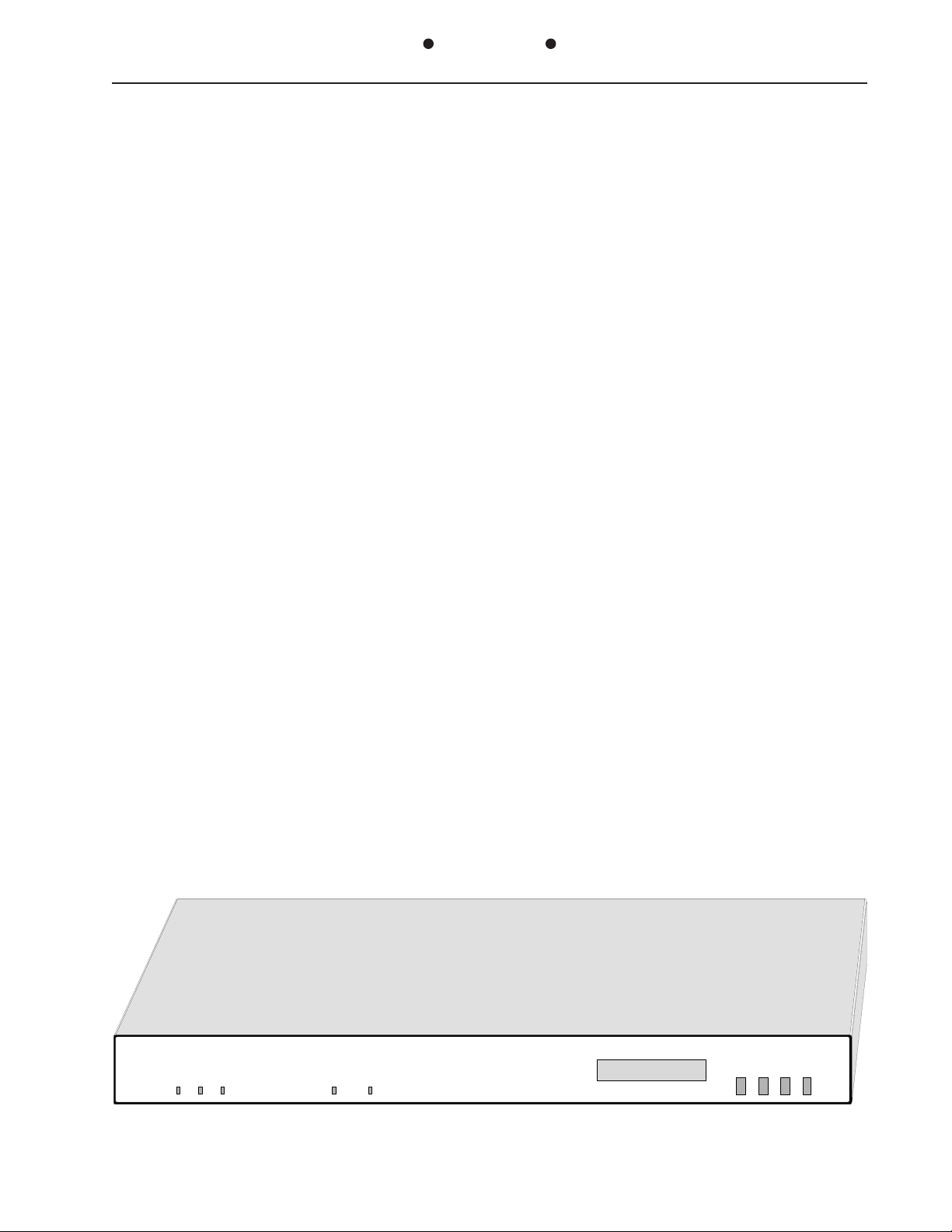
The 3046 (CTS DDS-MUX) has six DB-25 (V.24 / RS-232) female connectors located on
the rear of the unit to attach the terminal devices and a DB-25 (V.24 / RS-232) or M-34
(V.35) female connector to connect to the DDS network (DSU/CSU) or modem. The
following interface leads are implemented on all DB-25 connectors: Chassis (1), TXD (2),
RXD (3), RTS (4), CTS (5), DSR (6), Sig Gnd (7), DCD (8), TXC (15), RXC (17), DTR (20).
TIME DIVISION
MULT IP LEXE R
PWR SD RD RDL SYNC
1-1
SYSTEM STATUS
SYNC --- ----
DDS MUX
CHN PAR VAL STR
OPERATION
Page 7

PATTON ELECTRONICS CO.INSTALLATION AND OPERATIONS MANUAL
138001UA
3046
The V.35 version of the 3046 (CTS DDS-MUX) has the following interface leads
implemented on the M34 connector: Chassis (A), TXD (P,S), RXD (R,T), RTS (C), CTS
(D), DSR (E), Sig Gnd (B), DCD (F), TXC (Y,AA), RXC (V,X), DTR (H).
Front Panel LEDs
Front panel LEDs are provided to indicate power is applied, Send Data (SD), Receive Data
(RD), In-Sync (SYNC) condition between the two DDS-MUX's and Remote Digital
Loopback indication (RDL).
Front Panel LCD and Push Buttons
An LCD display and four push button controls are provided to configure the 3046 (CTS
DDS-MUX). The CHNL (Channel) push button selects which channel to configure. The
PAR (Parameter) push button selects what parameter to configure on a channel. The VAL
(Value) push button selects the Value to set the parameter to. The STR (Store) push
button stores the new configuration and sets all the channels and composite port to those
values. Current conditions set into the 3046 (CTS DDS-MUX) are indicated on the LCD
with an Asterisk (*).
Loopback Selection
Each channel can be individually looped back upon itself locally for diagnostics of the
communication system. In addition, the composite can be forced into remote loopback. All
loopbacks are commanded via the LCD/Pushbutton interface. The RDL LED is illuminated
on the 3046 (CTS DDS-MUX) that receives the remote loopback command as an
indication of the loopback condition.
Power Supply
A linear power supply is located internally, with an external 110/220VA switch located on
the rear of the unit. Approvals granted are MET, c-MET and CE.
Installation Options
The 3046 (CTS DDS-MUX) is supplied in an attractive textured aluminium enclosure that
will blend in with other data accessories when used as a standalone unit on a desktop.The
unit can also be installed in either a 19" or 23" cabinet, by simply installing the supplied
Rackmount hardware.
OPERATION
1-2
Page 8

PATTON ELECTRONICS CO.INSTALLATION AND OPERATIONS MANUAL3046
138001UA
Caution: Disconnect the POWER Before Removing The Cover
Vorsicht: Befor Deckung Abnehmen Mach Strom Zu.
CHAPTER 2 - SETUP AND INSTALLATION
Power Connection
Before connecting the 3046 (CTS DDS-MUX) to a AC power source the top cover must be
installed and secured with the supplied #8-32 screws. The unit is supplied with a 110/
220VAC voltage switch. Turn the switch
with a coin or screw driver to the
appropriate voltage for your country.
EXAMPLE: In the United States of
America, set to 110VAC. The unit is
supplied with a IEC power connector
next to the voltage select switch. Plug
the power cord into the connector
until it is firmly seated. You may now
connect the power cord into your AC
outlet.
CHAN 1
IEC Power Connector
110 / 220VA Switch
Fuse Drawer
COMPOSITE
220
110
Factory Configuration Switch Settings
The 3046 (CTS DDS-MUX) is configured prior to shipment with the switches set to the
following default positions:
COMPOSITE: if Low Speed, SPEED (19.2), MODE (3), LP-BK (DIS)
if High Speed, SPEED (64K), MODE (3), LP-BK (DIS)
CHAN 1 thru CHAN 3: SPEED(4800), MODE (SYN), CTS-DL (0), CD-SEL (SYN),
LP-BK (DIS)
CHAN 4 thru CHAN 6: SPEED(1200), MODE (SYN), CTS-DL (0), CD-SEL (SYN),
LP-BK (DIS)
If the system application requires one or more of the default settings to be changed, use
the LCD and push button switches to change the configuration of the 3046 (CTS DDSMUX) as needed.
The 3046/V24 (CTS DDS-MUX-V24) is factory set to low speed (E2 Installed), the 3046/
V24 (CTS DDS-MUX-V.35) is factory set to high speed (E2 Removed).
Disassembly
Removal of the cover is not required for operation or configuration of the 3046/V24 (CTS
DDS-MUX). Only a factory trained, qualified service technician should ever attempt to
remove the cover.
2-1
SETUP & INSTALLATION
Page 9

PATTON ELECTRONICS CO.INSTALLATION AND OPERATIONS MANUAL3046
138001UA
Installation
Select an appropriate location accessible to and within six feet of an AC power outlet. The
outlet must have a ground pin receptacle for product warranty. The cabling between each
attached device and the 3046 (CTS DDS-MUX) should be "Straight Through", shielded and
terminated with male connectors. Channels are marked PORT 1 through PORT 6: the
Master Port is marked, COMPOSITE. Secure other terminals to be serviced to the
remaining "PORT" connectors. Connect the DSU/CSU or modem to the connector
designated "COMPOSITE".
Push Buttons
All configuration is performed with the four front panel push buttons and the front panel
LCD display.
The CHN push button cycles the first field on the LCD display in the following sequence:
SYSTEM STATUS → COMP → CH1 → CH
NOTE: "CH
n" is the highest channel number allowed based on the current MODE selected
n → SYSTEM STATUS
for the COMPOSITE link. Factory default for mode is 3, so the highest channel
number will be CH6 if the configuration has not been modified.
The PAR push button cycles the second field on the LCD display in the following
sequence:
SPEED
→→
→ MODE
→→
→→
→ CHR-LEN
→→
→→
→ CTS-DL
→→
→→
→ CD-SEL
→→
→→
→ LP-BK → SPEED
→→
The CHR-LEN is only displayed when the selected channel is in asynchronous mode.
CTS-DL and CD-SEL are only displayed for channels not for the composite port.
The VAL push button cycles the third field on the LCD display to select the value to assign
to each of the modes for each channel.
The STR push button stores the selected values and re-configures the 3046 (CTS DDSMUX) as displayed in the LCD. The LCD and push buttons can be used to cycle through
all menus without disturbing the operation of the 3046 (CTS DDS-MUX). The value
displayed will only be activated when the STR push button is pushed. If it is desired not to
affect a change to the configuration, simply return to the SYSTEM STATUS display without
pushing the STR push button. The displayed values will be returned to the last stored
value after 10 minutes.
SETUP & INSTALLATION
2-2
Page 10

PATTON ELECTRONICS CO.INSTALLATION AND OPERATIONS MANUAL3046
138001UA
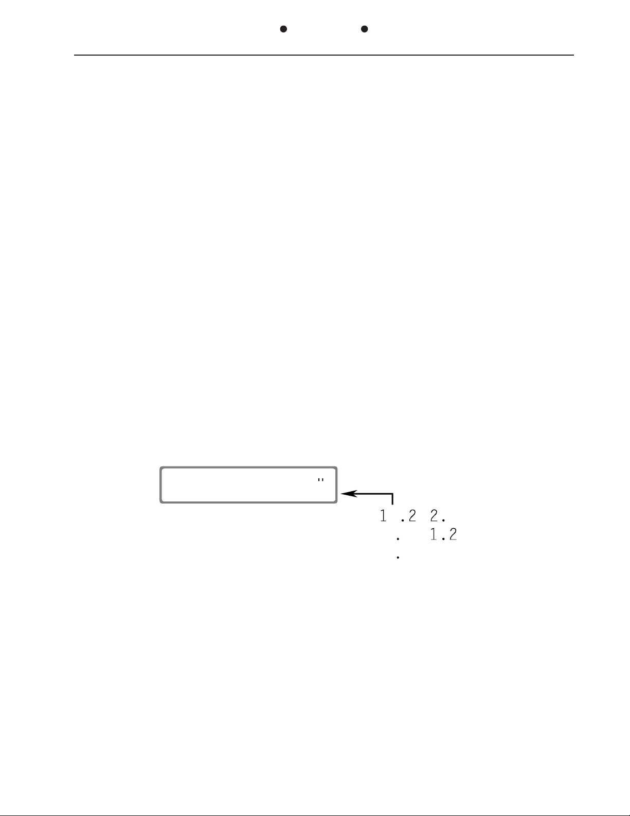
LCD SYSTEM STATUS Display
During normal operation the 3046 (CTS DDS-MUX) will be in the SYSTEM STATUS display.
This display indicates synchronization with the remote end by the SYNC message
SYSTEM STATUS
SYNC --- ----
1013A001
If the two 3046s (CTS DDS-MUX) are not in sync, the display will indicate this by displaying
dashes where the SYNC message is.
SYSTEM STATUS
---- --- ----
1013A001
When the 3046 (CTS DDS-MUX) is in sync it can receive a loopback command from the
remote end of the link. This Remote Digital Loopback command is indicated on the LCD in
the Middle of the SYSTEM STATUS display as RDL.
SYSTEM STATUS
SYNC RDL ----
1013A001
If any channel is looped back within the 3046 (CTS DDS-MUX), an indication is displayed
in the last position of the SYSTEM STATUS display, indicating that some loopback condition
exists at the originating end with the LOOP message.
SYSTEM STATUS
SYNC --- LOOP
1013A001
Composite Link Configuration
The composite configuration allows the selection of DDS rate and number of active
channels provided by the 3046 (CTS DDS-MUX). The current setting is identified by an
asterisk next to the values in the shown on the bottom line in the last position.
CH PARAM VAL
COMP SPEED 19.2*
1013A002
2-3
SETUP & INSTALLATION
Page 11

PATTON ELECTRONICS CO.INSTALLATION AND OPERATIONS MANUAL3046
138001UA
Speed
If a mode is selected that does not support the currently configured value or a parameter
available in the current configuration, an asterisk will not appear on any value for that
particular mode.
To select a composite SPEED from the SYSTEM STATUS display, press the CHN push
button once and the PAR push button until the following LCD display appears:
CH PARAM VAL
COMP SPEED 19.2*
All Displays Shown
1013X002
in Factory Default
9.6
14.4
or
56K
64K
19.2
Press the VAL push button until the desired value appears. Press STR to configure the
3046 (CTS DDS-MUX) or CHN and PAR to select additional configuration parameters.
Changing any Parameter value and pressing the STR for the composite port
loss of data for all channels.
WILL
cause
SETUP & INSTALLATION
2-4
Page 12

PATTON ELECTRONICS CO.INSTALLATION AND OPERATIONS MANUAL3046
138001UA
Mode
The mode parameter selects the number of active channels and the maximum speed each
active channel can operate. The following chart outlines the rates/channels available for
each of the modes. (E2 installed 9.6K,14.4K & 19.2K, E2 Removed 56K & 64K)
Composite Speed 9.6K
Mode CH 1 CH 2 CH 3 CH 4 CH 5 CH 6
1
2
3
Mode CH 1 CH 2 CH 3 CH 4 CH 5 CH 6
1
2
3
Mode CH 1 CH 2 CH 3 CH 4 CH 5 CH 6
1
2
3
Mode CH 1 CH 2 CH 3 CH 4 CH 5 CH 6
1
2
3
Mode CH 1 CH 2 CH 3 CH 4 CH 5 CH 6
1
2
3
4.8 2.4 1.2
2.4 2.4 2.4 1.2
2.4 1.2 1.2 1.2 1.2 1.2
Composite Speed 14.4K
9.6 2.4 1.2
4.8 4.8 1.2 1.2
2.4 1.2 1.2 1.2 1.2 1.2
Composite Speed 19.2K
9.6 4.8 2.4 1.2
4.8 4.8 4.8 2.4 1.2
4.8 4.8 4.8 1.2 1.2 1.2
Composite Speed 56K
19.2 19.2 9.6 4.8
19.2 9.6 9.6 9.6 4.8
9.6 9.6 9.6 9.6 9.6 4.8
Composite Speed 64K
19.2 19.2 9.6 9.6
19.2 9.6 9.6 9.6 9.6
9.6 9.6 9.6 9.6 9.6 9.6
Not Available Not Available Not Available
Not Available Not Available
Not Available Not Available Not Available
Not Available Not Available
Not Available Not Available
Not Available
Not Available Not Available
Not Available
Not Available Not Available
Not Available
To select composite MODE from the SYSTEM STATUS display, press the CHN push button
once and the PAR push button until the following LCD display appears:
CH PARAM VAL
COMP MODE 3*
1013A002
2-5
SETUP & INSTALLATION
Page 13

PATTON ELECTRONICS CO.INSTALLATION AND OPERATIONS MANUAL3046
138001UA
Press the VAL push button until the desired value appears. Press STR to configure the
3046 (CTS DDS-MUX) or CHN and PAR to select additional configuration parameters.
Changing any Parameter value and pressing the STR for the composite port
WILL
cause
loss of data for all channels.
Remote Digital Loopback
The Remote Digital Loopback parameter directs the 3046 (CTS DDS-MUX) at the remote
site to loopback its master channel to the attached DSU/CSU. This is a testing mode and
will cause data from all channels to be looped back at the same time.
To select composite LP-BK (Remote Digital Loopback) from the SYSTEM STATUS display,
press the CHN push button once and the PAR push button until the following LCD display
appears:
CH PARAM VAL
COMP LP-BK DIS*
1013A002
Press the VAL push button until the desired value appears. Press STR to configure the
3046 (CTS DDS-MUX) or CHN and PAR to select additional configuration parameters.
Changing any Parameter value and pressing the STR for the composite port
WILL
cause
loss of data for all channels.
When enabled, the
Remote
3046 (CTS DDS-MUX) will go into digital loopback and display:
SYSTEM STATUS
SYNC RDL ----
1013A001
The local 3046 (CTS DDS-MUX) will display as follows when returned to the SYSTEM
STATUS display:
SETUP & INSTALLATION
SYSTEM STATUS
SYNC --- LOOP
1013A001
2-6
Page 14
PATTON ELECTRONICS CO.INSTALLATION AND OPERATIONS MANUAL3046
138001UA
Channel Configuration
The channel configuration menus allow the selection of channel speed, mode, number of
bits per element in asynchronous mode, CTS delay, Carrier Detect function and Local
loopback function. Only channels that are active based on the selected mode in the
composite configuration will be displayed. The current setting is identified by an asterisk
next to the values shown on the bottom line in the last position in an identical fashion to the
composite configuration.
If a mode is selected that does not support the currently configured value or a parameter is
unavailable in the current configuration, an asterisk will not appear on any value for that
particular mode.
Speed
The Channel Speed parameter is used to set the baud rate of each individual channel.
The maximum rate available for each channel is set with the composite mode selection.
Any speed at or below the maximum for the composite mode can be selected with this
parameter.
To select a channel SPEED from the SYSTEM STATUS display, press the CHN push button
until the desired channel appears and the PAR push button until the following LCD display
appears:
CH PARAM VAL
CHn SPEED 9.6*
1013X003
Press the VAL push button until the desired value appears. Press STR to configure the
3046 (CTS DDS-MUX) or CHN and PAR to select additional configuration parameters.
Changing any Parameter value and pressing the STR for the channel port
loss of data for that channel.
WILL
cause
2-7
SETUP & INSTALLATION
Page 15

PATTON ELECTRONICS CO.INSTALLATION AND OPERATIONS MANUAL3046
138001UA
Mode
The Channel Mode parameter is used to select Synchronous or Asynchronous operation
for the channel. Each channel is individually selected for sync / async. Channels must be
configured identically on both sides of the link. If Channel 1 is async on the local end,
Channel 1 must also be async on the remote end.
To select a channel MODE from the SYSTEM STATUS display, press the CHN push button
until the desired channel appears and the PAR push button until the following LCD display
appears:
CH PARAM VAL
CHn MODE SYN*
1013A003
Press the VAL push button until the desired value appears. Press STR to configure the
3046 (CTS DDS-MUX) or CHN and PAR to select additional configuration parameters.
Changing any Parameter value and pressing the STR for the channel port
WILL
cause
loss of data for that channel.
Character Length
Async character length is selected by using the CHR-LEN parameter. As with mode, both
sides of the link must be configured the same. When selecting an element length, the
parity bit, start and stop bits must be considered as part of the data. If 7 bits, even parity,
one stop is desired then CHR-LEN of 10 should be selected (1-start, 7-data, 1-parity, 1stop).
To select a channel CHR-LEN from the SYSTEM STATUS display, press the CHN push
button until the desired channel appears and the PAR push button until the following LCD
display appears:
CH PARAM VAL
CHn CHR-LEN 10*
1013A003
This parameter is only available if the channel is configured as asynchronous.
SETUP & INSTALLATION
2-8
Page 16

PATTON ELECTRONICS CO.INSTALLATION AND OPERATIONS MANUAL3046
138001UA
Press the VAL push button until the desired value appears. Press STR to configure the
3046 (CTS DDS-MUX) or CHN and PAR to select additional configuration parameters.
Changing any Parameter value and pressing the STR for the channel port
WILL
cause
loss of data for that channel.
CTS Delay
The CTS Delay parameter is used to control the amount of delay to the CTS after the RTS
is raised. If ON is selected, CTS is constantly active. If 0M is selected CTS becomes active
immediately after RTS becomes active. Any other option is the time in milliseconds after
RTS becomes active for CTS to become active.
To select a channel CTS-DL (Clear to Send Delay) from the SYSTEM STATUS display,
press the CHN push button until the desired channel appears and the PAR push button
until the following LCD display appears:
CH PARAM VAL
CHn CTS-DL 0M*
1013A003
Press the VAL push button until the desired value appears. Press STR to configure the
3046 (CTS DDS-MUX), or CHN and PAR to select additional configuration parameters.
Changing any Parameter value and pressing the STR for the channel port may cause loss
of data for that channel.
DCD Source
The DCD Select parameter is used to select the source of the local Carrier detect interface
lead for each channel. Setting the option to SYN will force DCD (pin 8) to follow the status
of the link sync signal. If the link is established and in sync the DCD will be active,
otherwise it will be inactive. The other option, RTS will force the local channel DCD to
follow the remote channel RTS (pin 4). This allows for switched carrier operation on a
channel by channel basis.
2-9
SETUP & INSTALLATION
Page 17

PATTON ELECTRONICS CO.INSTALLATION AND OPERATIONS MANUAL3046
138001UA
To select a channel CD-SEL (Carrier Detect Source Select) from the SYSTEM STATUS
display, press the CHN push button until the desired channel appears and the PAR push
button until the following LCD display appears:
CH PARAM VAL
CHn CD-SEL SYN*
Press the VAL push button until the desired value appears. Press STR to configure the
3046 (CTS DDS-MUX) or CHN and PAR to select additional configuration parameters.
Changing any Parameter value and pressing the STR for the channel port may cause loss
of data for that channel.
1013A003
Local Digital Loopback
The Loopback parameter is used to select the local loopback test function. If loopback is
enabled, the data that arrives at the channel connector is looped back to the terminal to
verify continuity of the data path to the 3046 (CTS DDS-MUX).
To select a channel LP-BK (Local Loopback) from the SYSTEM STATUS display, press the
CHN push button until the desired channel appears and the PAR push button until the
following LCD display appears:
CH PARAM VAL
CHn LP-BK DIS*
Press the VAL push button until the desired value appears. Press STR to configure the
3046 (CTS DDS-MUX), or CHN and PAR to select additional configuration parameters.
Changing any Parameter value and pressing the STR for the channel port
loss of data for that channel.
1013A003
WILL
cause
When any channel is in loopback the local 3046 (CTS DDS-MUX) will display as follows
when returned to the SYSTEM STATUS display:
SYSTEM STATUS
SYNC --- LOOP
1013A001
SETUP & INSTALLATION
2-10
Page 18

APPENDIX
PATTON ELECTRONICS CO.INSTALLATION AND OPERATIONS MANUAL3046
138001UA
SG
B
FGEDSR
A
CD
F
CTS
D
RTSHDTR
C
J
RD(A)VRT(A)
L R
N T
TD(A)
K
P
RD(B)
TD(B)
S
RT(B)
X
TT(A)
U Y
W AA
Z DD JJ
BB FF LL
CC HH MM
TT(B)
EE KKM
NN
M-34 / V.35 Composite Interface Pins Supported
DB-25 RS-232
Transmit Clock (from DCE)
Receive Clock (from DCE)
Data Terminal Ready (from DTE)
Channel Interface Pins Supported
14
15
16
17
18
19
20
21
22
23
24
25
A-1
Shield (common)
1
Transmit Data (from DTE)
2
3
Receive Data (from DCE)
4
Request to Send (from DTE)
Clear To Send (from DCE)
5
6
Data Set Ready (from DCE)
7
Signal Ground (common)
8
Data Carrier Detect (from DCE)
9
10
11
12
13
APPENDIX
Page 19

PATTON ELECTRONICS CO.INSTALLATION AND OPERATIONS MANUAL3046
138001UA
TECHNICAL SPECIFICATIONS
Applications
Multiple Sync or Async Terminals
sharing one DSU/CSU or modem link
Capacity
Six RS-232 Sync/Async DTE devices
One RS-232 or V.35 DCE Master
Channel
Data Format
Data transparent at all data rates
Composite Data Rates
9.6K, 14.4K, 19.2K or 56K, 64Kbps
Sub-channel Data Rates
Front Panel
Indicators: .. Power, Send Data, Receive
Data, Remote Digital Loop,
Sync, Configuration LCD
Switches: ... Channel, Parameter, Value,
Store
Power Source
100-120/200-240 Vac, 50 to 60 Hz,
0.16/0.08 A, Switch Selectable
Environmental
Operating Temp: ... 32° to 122°F (0° to
50°C)
Relative Humidity: .. 5 to 90% non-
condensing
Altitude: ............... 0 to 10,000 feet
1.2K thru 9.6Kbps (19.2K HS)
Sub-channel Interface
Channels: RS-232 (DB25) Female
connectors
Modem Interface
Composite: RS-232 (DB-25) Female
Connector or V.35 (M34)
Certifications
MET, c-MET & CE
Dimensions
Height: ... 1.75 inches (4.44 cm)
Width: .... 17.00 inches (43.18 cm)
Length:... 11.00 inches (18.93 cm)
Weight
4.5 lbs (2.1 Kg)
APPENDIX
A-2
Page 20

PATTON ELECTRONICS CO.INSTALLATION AND OPERATIONS MANUAL3046
CHN Button Loop
138001UA
SYSTEM
STATUS
SYNC
RDL
LOOP
PAR
Button
Loop
Composite Channel
VAL
Button
Loop
SPEED
MODE
CHR-LEN
CTS-DL
CD-SEL
LP-BK
SPEED
MODE
LP-BK
9.6
14.4
19.2
1
2
3
ENA
DIS
56K
64K
Command Tree
19.2
9.6
4.8
SYN
ASY
10
11
0M
1M
3M
6M
SYN
RTS
ENA
DIS
2.4
1.2
9
8
13M
26M
53M
ON
Asy nc Term inal
Sync H os t
Asy nc Term inal
TIME DIVISION
MULTIPLEXER
PWRSDRDRDLSYNC
(CTS DDS-MUX)
3046
SYSTEM STATUS
SYNC --- ----
High Speed
DSU/C SU
DDS
Network
DDS MUX
CHNPARVALSTR
Typical Application
A-3
High Speed
DSU/C SU
TIME DIVISION
MULTIPLEXER
PWRSDRDRDLSYNC
SYSTEM STATUS
SYNC --- ----
3046
(CTS DDS-MUX)
Asy nc Term inal
DDS MUX
CHNPARVALSTR
Sync Terminal
Async Terminal
Sync Terminal
1010XAP1
APPENDIX
Page 21

B
7622 Rickenbacker Drive
Gaithersburg, MD 20879
Sales: 301 975-1000 Support: 301 975-1007
Web Address: www.patton.com
 Loading...