

Page 1

B
STATISTICAL MULTIPLEXER
Doc #: 154001UA
Part #: 07M3028-A
3028 Turbo
(CTS 2031
INSTALLATION AND OPERATIONS MANUAL
May 31, 2000
TURBO
)
An ISO-9001
Certified Company
Copyright© 2000 Patton Electronics Co., All Rights Reserved
Page 2

B
STATISTICAL MULTIPLEXER
Doc #: 154001UA
Part #: 07M3028-A
3028 Turbo
(CTS 2031
INSTALLATION AND OPERATIONS MANUAL
TURBO
)
An ISO-9001
Certified Company
Copyright© 2000 Patton Electronics Co., All Rights Reserved
Page 3

PrefacePreface
Preface
PrefacePreface
AUDIENCE ANDAUDIENCE AND
AUDIENCE AND
AUDIENCE ANDAUDIENCE AND
OBJECTIVESOBJECTIVES
OBJECTIVES
OBJECTIVESOBJECTIVES
RELATED DOCUMENTSRELATED DOCUMENTS
RELATED DOCUMENTS
RELATED DOCUMENTSRELATED DOCUMENTS
PROPRIETARY NOTICEPROPRIETARY NOTICE
PROPRIETARY NOTICE
PROPRIETARY NOTICEPROPRIETARY NOTICE
SERVICESERVICE
SERVICE
SERVICESERVICE
This manual contains information about the installation and operation of the
3028Turbo (CTS 2031 Turbo) Statistical Multiplexer. The manual is intended for
use by the technician installing the equipment and the operator using the equip-
ment. This manual assumes that its user is familiar with basic telecommunica-
tions and computer terminology.
2980-A2-GN30 DCX 840 Installation, Operation and Maintenance Manual
2985-A2-GN30 DCX 840 Installation, Operation and Maintenance Manual
The information contained herein is proprietary and confidential to Patton
Electronics Co. Any reproduction or redistribution of this publication, in whole or
in part, is expressly prohibited unless written authorization is given by Patton
Electronics Co.
Patton Electronics Co. (hereafter referred to as Patton) warrants that its equipment
is free from any defects in materials and workmanship. The warranty period shall
be two years from the date of shipment of equipment. Pattons sole obligation
under its warranty is limited to the repair or replacement of the defective equip-
ment. This warranty will not extend to equipment subjected to accident, misuse,
alterations or repair not made by Patton or authorized by Patton in writing.
All warranty and non-warranty repairs must be returned freight prepaid and
insured to Patton Electronics. All returns must have a Return Materials Authoriza-
tion number on the outside of the shipping container. This number may be ob-
tained from Patton Electronics Technical Services at:
PUBLICATION NOTICEPUBLICATION NOTICE
PUBLICATION NOTICE
PUBLICATION NOTICEPUBLICATION NOTICE
Tel: (301) 975-1007;
email: support@patton.com;
or, Web: http://www.patton.com.
NOTE: Packages received without an RMA number will not be accepted.
Patton Electronics technical staff is also available to answer any questions that
might arise concerning the installation or use of your Patton devices. Technical
Service hours: 8AM to 5PM EST, Monday through Friday.rations or repair not
made by Patton or authorized by Patton in writing.
This manual has been compiled and checked for accuracy. The information in this
manual does not constitute a warranty of performance. Patton reserves the right to
revise this publication and make changes from time to time in the content thereof.
Patton assumes no liability for losses incurred as a result of out-of-date or incorrect
information contained in this manual.
DCX is a trademark of AT&T Paradyne.
ENQ/ACK is a registered trademark of Hewlett-Packard Corporation.
Paradyne in a registered trademark of AT&T Paradyne.
Tandem is a registered trademark of Tandem Corporation.
T-Pause is a registered trademark of Tandem Corporation.
Wang is a registered trademark of Wang Laboritories, Inc.
2030 Statistical Multiplexer is a registered trademark of AT&T Paradyne.
154001UA i
Page 4

WARRANTIES: Patton Electronics Co. (hereafter referred to as Patton) warrants that its
equipment is free from any defects in materials and workmanship. The warranty period
shall be two years from the date of shipment of equipment. Pattons sole obligation
under its warranty is limited to the repair or replacement of the defective equipment,
provided it is returned to Patton, transportation prepaid, within a reasonable period. This
warranty will not extend to equipment subjected to accident, misuse, alterations or repair
not made by Patton or authorized by Patton in writing.
WARRANTY NOTICEWARRANTY NOTICE
WARRANTY NOTICE
WARRANTY NOTICEWARRANTY NOTICE
The Patton MSDs generate and use radio frequency energy, and if not installed and used
properlythat is, in strict accordance with the manufacturers instructionsmay cause
interference to radio and television reception. The Patton MSDs have been tested and
found to comply with the limits for Class A computing devices in accordance with the
specifications in Subpart J of Part 15 of FCC rules, which are designed to provide reason-
able protection from such interference in a commercial installation. However, there is no
guarantee that interference will not occur in a particular installation. If the Patton MSDs
do cause interference to radio or television reception, which can be determined by
disconnecting the cables, the user is encouraged to try to correct the interference by one
or more of the following measures: moving the computing equipment away from the
receiver, re-orienting the receiving antenna, and/or plugging the receiving equipment
into a different AC outlet (such that the computing equipment and receiver are on
different branches).
The CE symbol on your Patton Electronics equipment indicates that it is in compliance
with the electromagnetic Compatibility (EMC) directive and the Low Voltage Directive
(LVD) of the European Union (EU). A Certificate of Compliance is available by contacting
Technical Support.
RADIO AND TVRADIO AND TV
RADIO AND TV
RADIO AND TVRADIO AND TV
INTERFERENCEINTERFERENCE
INTERFERENCE
INTERFERENCEINTERFERENCE
CE NOTICECE NOTICE
CE NOTICE
CE NOTICECE NOTICE
B
7622 Rickenbacker Drive
Gaithersburg, Maryland 20879
Phone 301 975-1000 FAX 301 975-1007
154001UAii
Page 5

TT
able of Contentsable of Contents
T
able of Contents
TT
able of Contentsable of Contents
1. Introduction and Setup
Overview ......................................................................................................... 1-1
Equipment supplied ..................................................................................... 1-3
Equipment Required But Not Supplied ..................................................... 1-3
Product Terminology .................................................................................... 1- 3
Unpacking and Setup ................................................................................... 1-4
Multiplexer Factory Defaults ....................................................................... 1-5
EIA Signals ..................................................................................................... 1-6
2. Operation of the 3028 Turbo Multiplexer
Overview ......................................................................................................... 2-2
Supervisory Function Overview ................................................................. 2-2
Front Panel Operation .................................................................................. 2-3
Terminal Operation ....................................................................................... 2-5
Modes of Operation ....................................................................................... 2-5
Standby Mode/Logoff .................................................................................. 2-6
Monitor Mode ................................................................................................ 2- 6
Memory Capability ........................................................................................ 2-10
Command Mode ............................................................................................ 2-10
Resetting The Multiplexer ............................................................................ 2-75
Appendices
A. Multiplexer Command Mode Summary ........................................... A-1
B. Technical Specifications ..................................................................... B-1
C. ASCII Character Codes ....................................................................... C-1
D. Multiplexer Parity Options ................................................................. D-1
E. Hewlett-Packard Protocol ................................................................... E-1
F. Tandem T-Pause and Wang Flow Control Methods ...................... F-1
G. Flow Control Translation .................................................................... G-1
H. Factory Hardware Option Settings.................................................... H-1
I. SDLC/HDLC Protocol ......................................................................... I-1
J. EIA Signal Exceptions ......................................................................... J-1
K. Rack-Mount Installation ..................................................................... K-1
L. Vorbereitungen zur Inbetriebnahme der Gerate .............................. L-1
Index
154001UA iii
Page 6
1. Introduction and Setup
20311-1
Supervisor
DCX Network Application
302 8Turbo
STATISTICAL
MU L TI PLEX ER
302 8Turbo
STATISTICAL
MU L TI PLEX ER
302 8Turbo
STATISTICAL
MU L TI PLEX ER
Point to Point Application
Supervisor
302 8Turbo
STATISTICAL
MU L TI PLEX ER
302 8Turbo
STATISTICAL
MU L TI PLEX ER
1.1.
1.
1.1.
OVERVIEWOVERVIEW
OVERVIEW
OVERVIEWOVERVIEW
Introduction and SetupIntroduction and Setup
Introduction and Setup
Introduction and SetupIntroduction and Setup
Overview .................................................................................................................................................. 1-1
Product Terminology .............................................................................................................................. 1-3
Equipment Supplied ...............................................................................................................................1-3
Equipment Required But Not Supplied ..............................................................................................1-3
Unpacking and Setup .............................................................................................................................1-4
Multiplexer Factory Defaults ................................................................................................................ 1-5
EIA Signals ............................................................................................................................................... 1-6
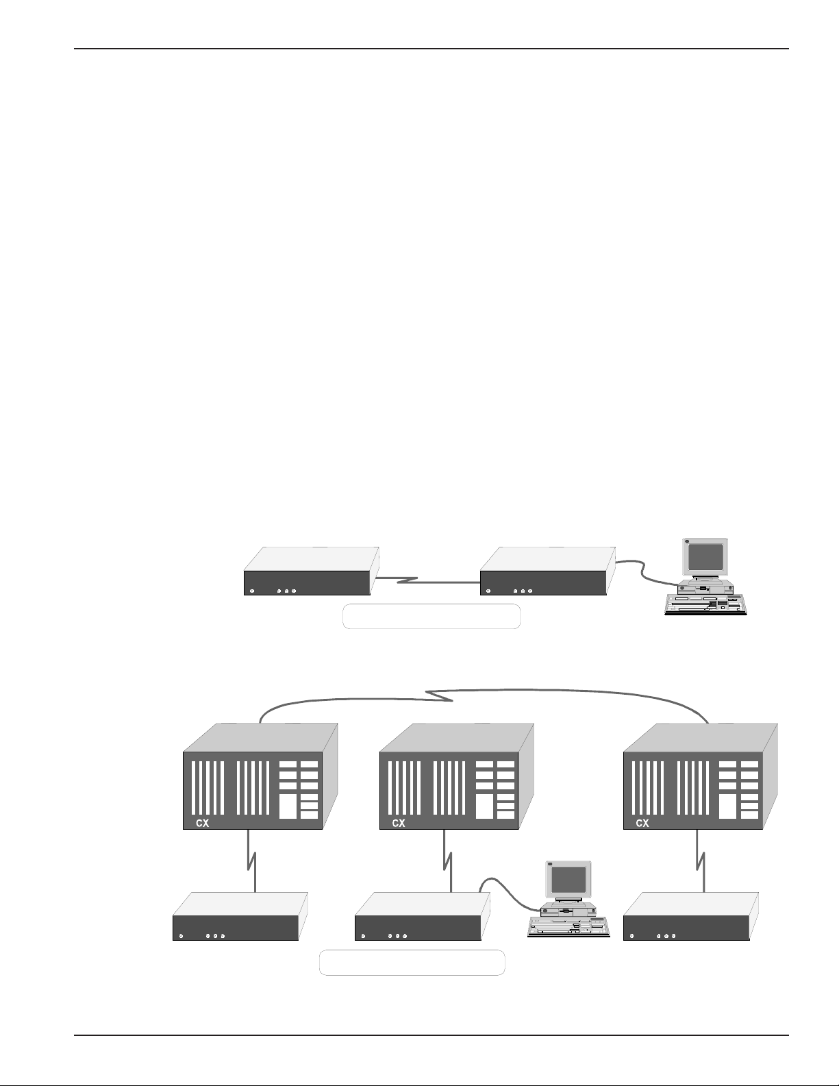
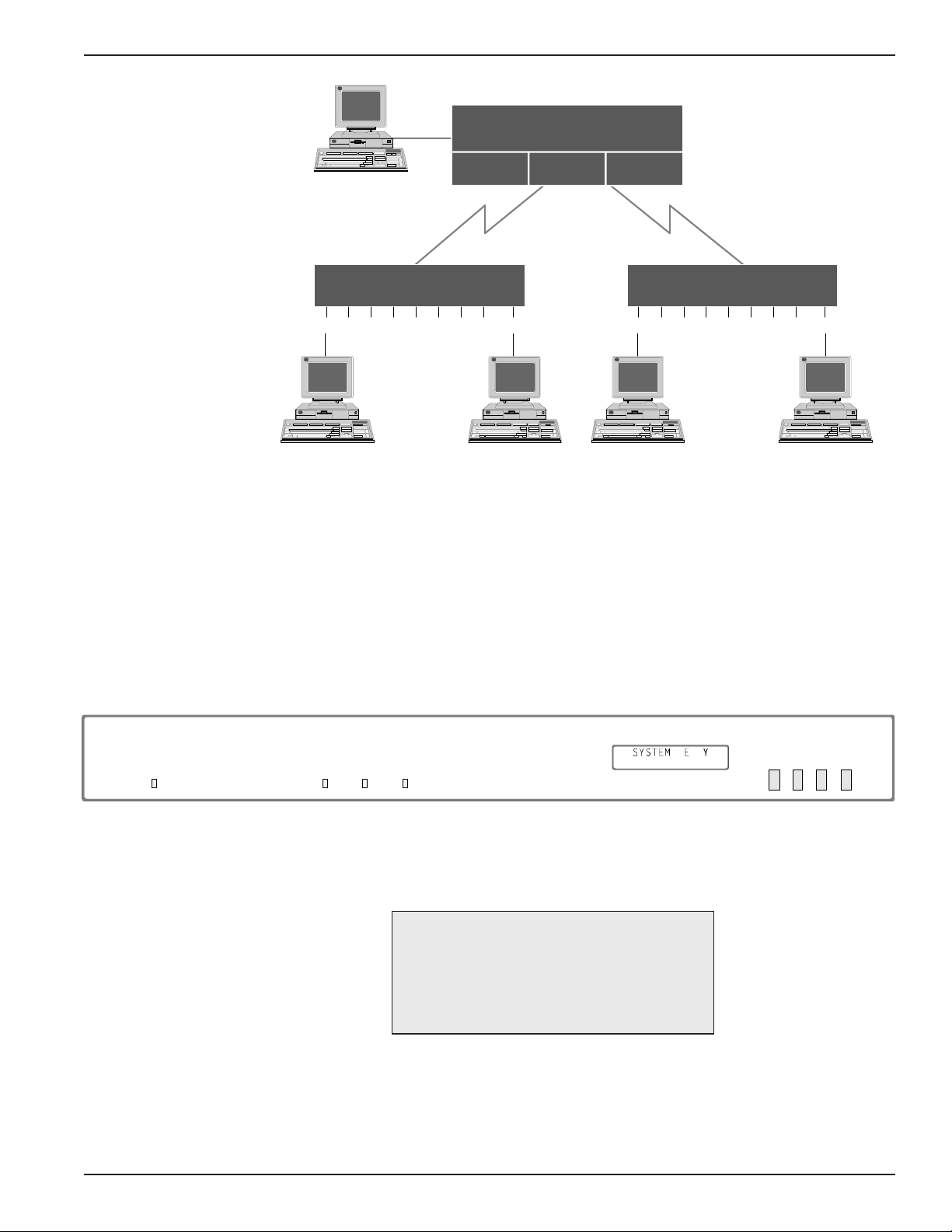
The 3028 Turbo (CTS 3028 Turbo (CTS 2031 Turbo)) Statistical Multiplexer has two
primary applications: Point-to-Point and DCX networking (Figure 1-1). Point-to-
Point operations in a single link environment supports up to eight terminals. All
of the DCX networking applications, including direct connections to a DCX 840 or
DCX 850 are supported. The 3028 Turbo (CTS 3028 Turbo (CTS 2031 Turbo)) also
supports the onward linking facilities through a DCX 825/871.
The SDLC/HDLC protocol is a standard feature that supports the bit-oriented
synchronous protocols.
154001UA 1-1
Figure 1-1. Multiplexer Product Application ExamplesFigure 1-1. Multiplexer Product Application Examples
Figure 1-1. Multiplexer Product Application Examples
Figure 1-1. Multiplexer Product Application ExamplesFigure 1-1. Multiplexer Product Application Examples
Page 7

2031 Turbo Statistical Multiplexer
The multiplexer combines data traffic from up to eight sources into a high-speed
composite link. Channel speeds supported are from 75bps to 19,200bps with an
automatic channel speed detection (AUTOBAUD) option up to 9,600bps. The
buffer management allows storage of 16K bytes to be shared on demand by the
channels. Each channel is assigned a minimum of 372 bytes of buffer space to
prevent lockout. Because of the buffering action of the 2031, the data rates on the
channel side of the multiplexer may total several times the actual link rate without
data loss. The multiplexer will handle an aggregate of 76,800 bps in constant full-
duplex traffic (with flow control) and a 64,000K bps link without loss of data.
The multiplexer can transmit control messages end-to-end to handle such things
as break propagation, EIA signal propagation, and autobaud speeds. The control
messages are transparent to the user. In addition, any of the EIA interface outputs
can be forced high or low through the user interface.
Multiplexer configuration and operation monitoring is accomplished in a variety
of ways. An ASCII asynchronous terminal can be attached to the supervisory port
on the back panel or to a data channel that has the supervisory access enabled, or
the front panel push-buttons and LCD display can be used. Another method of
access is from a remote multiplexer in a point-to-point or a DCX network applica-
tion. Access to the supervisory function can be password protected for security.
All parameters are contained in nonvolatile storage.
The 3028 Turbo (CTS 3028 Turbo (CTS 2031 Turbo)) multiplexer is designed to be a
cost-effective point-to-point multiplexer. At the same time, it is fully compatible
with the CTS 2031 and the AT&T Paradyne DCX family of multiplexers and can
serve as an 8-channel node in a DCX network.
154001UA1-2
Page 8

1. Introduction and Setup
PRODUCTPRODUCT
PRODUCT
PRODUCTPRODUCT
TERMINOLOGYTERMINOLOGY
TERMINOLOGY
TERMINOLOGYTERMINOLOGY
The following terms are used when referring to the multiplexer:
CHANNEL
LINK The high-speed composite multiplexed interface.
CHANNEL
PORT
LINK PORT The physical interface for a link.
SUPERVISORY
PORT
DCE Data Communication Equipment -- This can be any
DTE Data Terminal Equipment -- This can be any terminal or
One of the eight possible low-speed port interfaces.
The physical interface for a channel.
The connector reserved for supervisor functions, such
as configuring channel parameters or monitoring status
and statistics.
Modem attached to the multiplexer on the Composite
port.
host attached to the multiplexer on a channel port.
EQUIPMENTEQUIPMENT
EQUIPMENT
EQUIPMENTEQUIPMENT
SUPPLIEDSUPPLIED
SUPPLIED
SUPPLIEDSUPPLIED
EQUIPMENTEQUIPMENT
EQUIPMENT
EQUIPMENTEQUIPMENT
REQUIRED BUTREQUIRED BUT
REQUIRED BUT
REQUIRED BUTREQUIRED BUT
NOT SUPPLIEDNOT SUPPLIED
NOT SUPPLIED
NOT SUPPLIEDNOT SUPPLIED
LCD Liquid Crystal Display -- This is located on the front
panel of the 3028 Turbo (CTS 3028 Turbo (CTS 2031
Turbo)). It displays two lines of 16 characters each.
NETWORK
APPLICATION
POINT-TO-POINT
APPLICATION
A shielded, Male to Female, straight through cable is supplied to connect the
multiplexer Composite Port to an external modem.
Customer-supplied RS-232-C I/O cables from each DTE to standard EIA 25-pin
female connectors are required. A special cable is needed when using the
Tandem T-Pause® Flow Control application (refer to Appendix F).
Modem tail circuit applications require crossover cables (Figure 1-3).
This term refers to the use of the 3028 Turbo (CTS 3028
Turbo (CTS 2031 Turbo)) multiplexer in a network of one
or more DCX devices.
This term refers to the use of the 3028 Turbo (CTS 2031
Turbo) multiplexer in direct communications with
another 3028 Turbo (CTS 2031 Turbo) multiplexer. This
application involves only two devices.
Note
Shielded RS-232-C I/O cables
are required.
154001UA 1-3
Page 9
2031 Turbo Statistical Multiplexer
The following lists the procedure for unpacking and setting up the 3028 Turbo
(CTS 2031 Turbo).
1. Remove the 3028 Turbo (CTS 2031 Turbo) from the box and place it on a
flat surface.
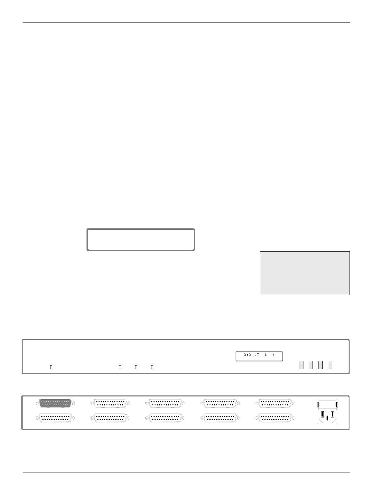
2. MODEM CONNECTION. Connect the supplied composite link cable to
the port labeled COMPOSITE on the rear panel (Figures 1-2) and then to
the modem. The Composite port is configured as a DTE to allow use of a
shielded, Male to Female, straight through cable to connect the Modem.
3. Connect the customer-supplied shielded, Male to Male, RS-232-C cables to
the selected ports and the DTEs, respectively.
4. The voltage selector is set to the proper line voltage for the area of the
world where the unit will be used at the factory. For the United States the
switch is set to 115V. Plug the female end of the power cable into the
receptacle on the rear panel and connect the other end to the power source.
The unit is operational when the POWER LED lights.
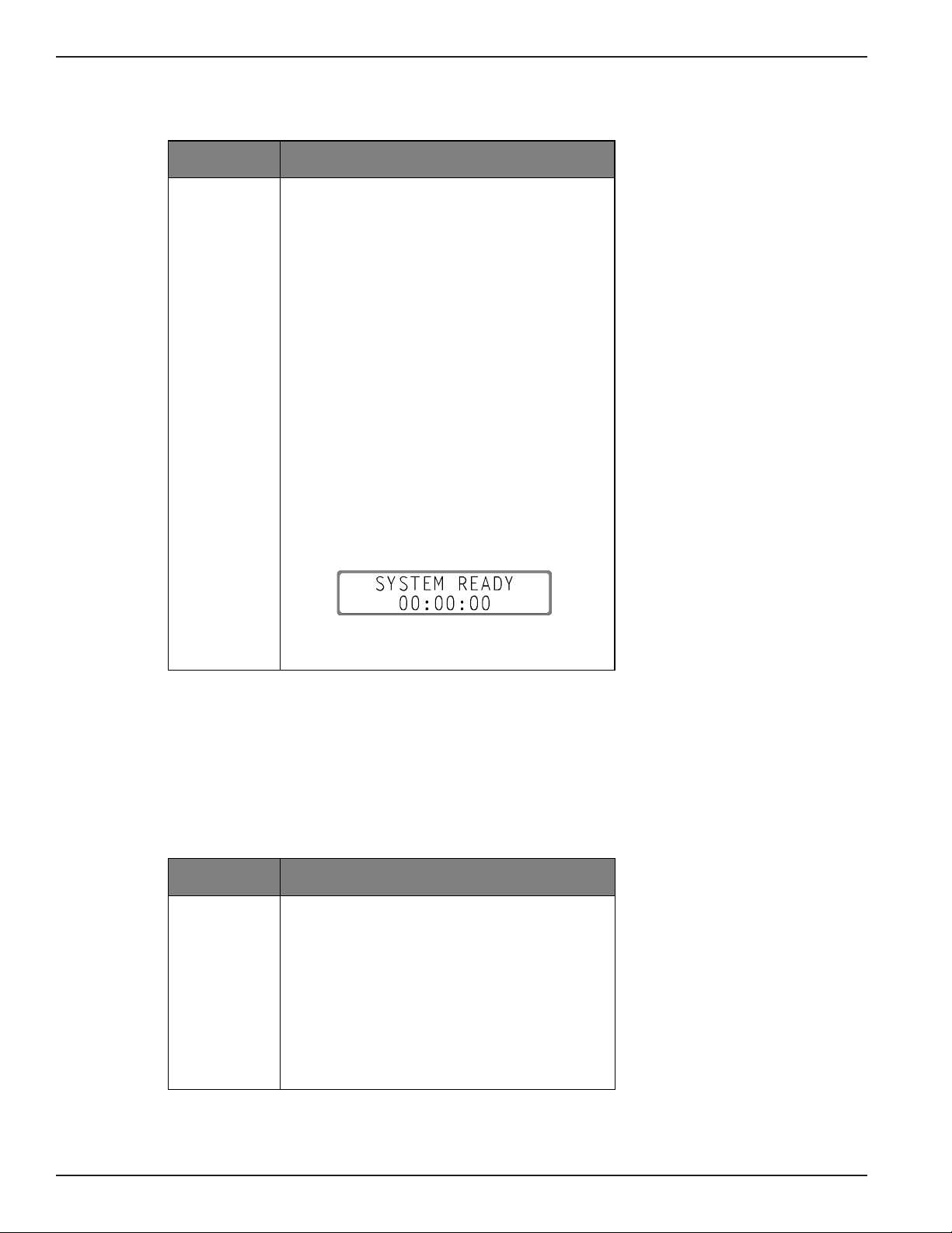
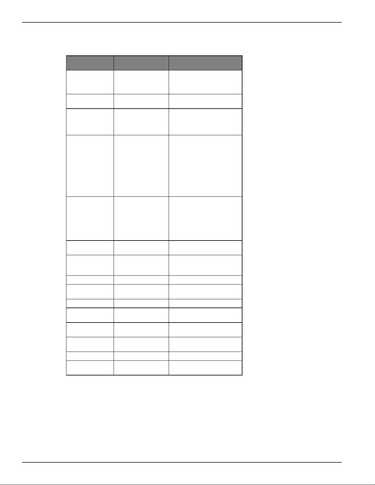
5. After the 3028 Turbo (CTS 2031 Turbo) has been attached to the proper
power source, it performs a series of tests to insure the integrity of the
system components. If the tests are passed, the multiplexer LCD displays:
UNPUNP
ACKING ANDACKING AND
UNP
ACKING AND
UNPUNP
ACKING ANDACKING AND
SETUPSETUP
SETUP
SETUPSETUP
SYSTEM READY
00:00:00
20312-51
and the system configuration can be performed. If any of the tests fail, the
LCD displays a message (refer to System Error Messages section). When
this message is displayed, cycle the power. If the error occurs again
contact your CTS service representative.
6. Connect a standard ASCII terminal, if used, to the 3028 Turbo (CTS 2031
Turbo) using a customer-supplied, straight-through, RS-232-C I/O cable at
the port labeled SUPERVISORY.
STATISTICAL
MULTIPLEXER
DATA LINK F LO W
POWE R LOSS DOWN CON TRO L
COMPOSI T E
SU PE R VISOR Y
PORT 7
PORT 8
PORT 5
PORT 6
PORT 3
PORT 4
Note
Shielded RS-232-C I/O cables
are required.
TU RBO
PORT 1
PORT 2
3028
NEX T L AST SEL M ON/ CL
CAUTIO N:
FOR CONTINUED
PROTECTION A GAINST
RISK OF FIRE
RE PLAC E ON L Y
WITH SAME TYPE
OF FUSE
Figure 1-2. Front & Rear Panel, Model 3028TurboFigure 1-2. Front & Rear Panel, Model 3028Turbo
Figure 1-2. Front & Rear Panel, Model 3028Turbo
Figure 1-2. Front & Rear Panel, Model 3028TurboFigure 1-2. Front & Rear Panel, Model 3028Turbo
20311-2
154001UA1-4
Page 10

1. Introduction and Setup
Connect the terminal to the power source and turn on the terminal.
PRESS: <supervisor logon character>
(default = CTRL + V)
The System Menu is Displayed
Check the following items if the System Menu does not appear.
Terminal cabling
Terminal power switch ON
Terminal speed 9600 (refer to terminal manual)
Multiplexer <supervisory logon character> is decimal 022
(default = CTRL + V) (refer to Appendix D)
Multiplexer stop bits (refer to Chapter 2)
Multiplexer parity (refer to Appendix D)
For additional information on these items refer to the indicated chap-
ters.
MULMUL
TIPLEXERTIPLEXER
MUL
TIPLEXER
MULMUL
TIPLEXERTIPLEXER
FACTORFACTOR
FACTOR
FACTORFACTOR
DEFDEF
AULAUL
DEF
AUL
DEFDEF
AULAUL
YY
Y
YY
TSTS
TS
TSTS
The multiplexer is configured at the factory with a set of default parameters.
Refer to Tables 1-1 and 1-2 for the default settings.
If you want to change any of the multiplexer parameters, refer to the appropri-
ate paragraph in Chapter 2.
Table 1-1. Supervisory Port DefaultsTable 1-1. Supervisory Port Defaults
Table 1-1. Supervisory Port Defaults
Table 1-1. Supervisory Port DefaultsTable 1-1. Supervisory Port Defaults
COMMAND PARAMETER
SUPERVISORY
PARAMETERS
SPEED 9600
DATA BITS 8
STOP BITS 1
PARITY NONE/SPACE
RV FL CTL NONE
(Reverse Flow Control)
DEFAULT
SETTING
154001UA 1-5
Page 11

2031 Turbo Statistical Multiplexer
Table 1-2. Channel Port Default Configuration SettingsTable 1-2. Channel Port Default Configuration Settings
Table 1-2. Channel Port Default Configuration Settings
Table 1-2. Channel Port Default Configuration SettingsTable 1-2. Channel Port Default Configuration Settings
COMMAND PARAMETER
CHANNEL
PARAMETERS
LINK
PARAMETERS
DEFAULT
SETTING
SPEED 9600
TYPE ASYNC
DATA BITS 8
STOP BITS 1
PARITY NONE/SPACE
FL CTL (Flow Control) DC3/DC1
FL CTL TR (Flow Control Translation) NO
RV FL CTL (Reverse Flow Control) NONE
EIA PROP (EIA Propigation) NO
BRK PROP (Break Propagation) NO
ECHOPLEX NO
FLYBACK (Flyback Buffering) NO
CTS-RTS (Clear-to-Send Ready-to-Send) NO
MSGS ENAB (Messages Enabled) NO
SPVR ENAB (Supervisor Enabled) NO
INAC DISC (Inactivity Disconnect) NO
DISC CHAR (Disconnect Character) CTL-T
LINK CLK SOURCE (Link Clock Source) EXTERN
LINK CLK RATE (Link Clock Rate) 9600
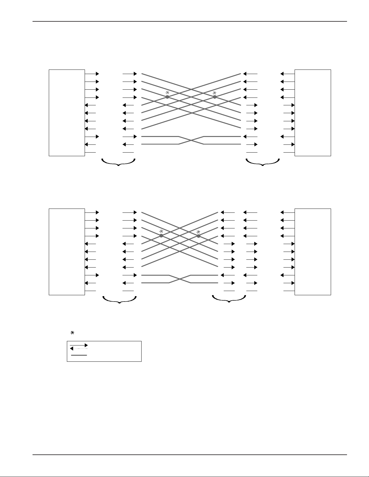
RS-232-C is defined in terms of a DTE at one end and a DCE at the other. Normally
this would be a terminal or host (DTE) and a modem (DCE). The 3028 Turbo (CTS
2031 Turbo) multiplexer is designed to play the role of a DCE normally. When
attached to a modem on the channel port however, the 3028 Turbo (CTS 2031 Turbo)
plays the role of a DTE with EIA signals exchanged through a special cable.
Figure 1-3 identifies the EIA signal propagation. EIA signal propagation must be
enabled for the channel, for signal propagation to take place.
The Composite port is configured as a DTE to allow it to be connected to a modem
(DCE) type device. The following signals are active on the Composite port: TXD
(2), RXD (3), TXC (15), RXC (17), RTS (4), CTS (5), DCD (8), DTR (20) and XTXC
(24). The composite link is synchronous, full duplex and point to point. Front
panel configuration allows the 3028 Turbo (CTS 2031 Turbo) to provide clocking on
the XTXC signal lead as well as take clocking from the RXC and TXC signal leads.
If DCD becomes inactive the 3028 Turbo (CTS 2031 Turbo) assumes the link is
down. RTS will be provided by the 3028 Turbo (CTS 2031 Turbo). CTS must be
returned by the modem for the 3028 Turbo (CTS 2031 Turbo) to send data and
establish a link. DTR is forced active by the 3028 Turbo (CTS 2031 Turbo) software.
EIA SIGNALSEIA SIGNALS
EIA SIGNALS
EIA SIGNALSEIA SIGNALS
154001UA1-6
Page 12
S
tandard Terminal / Host Connection
1. Introduction and Setup
Host
Host
Pin-to-
DTE DTE
DRS
BO
RTS
DTR
CTS
RI
DCD
DSR
TXD
RXD
GND
Pin
23
25
20
22
Pin
Cable
4
5
8
6
2
3
7
Pin-to-
Pin
Cable
Pin
23
20
25
22
DRS
BO
RTS
4
DTR
CTS
5
RI
DCD
8
DSR
6
TXD
2
RXD
3
GND
7
Multiplexer Multiplexer
Tail Circuit Application
DRS
BO
RTS
DTR
CTS
RI
DCD
DSR
TXD
RXD
GND
23
25
4
20
5
22
8
6
2
3
7
Pin-to-
Pin
Cable
Crossover
Cable
23
25
20
22
DCEDTE
CTS
5
RI
22
DCD
23
25
20
8
DSR
6
DRS
BO
RTS
4
DTR
RXD
3
TXD
2
GND
7
4
5
8
6
2
3
7
Terminal
Modem
Multiplexer
Optional Under Software Control
Physical Propagation
Software Propagation
Figure 1-3. EIA SignalsFigure 1-3. EIA Signals
Figure 1-3. EIA Signals
Figure 1-3. EIA SignalsFigure 1-3. EIA Signals
154001UA 1-7
1
Multiplexer
Tail Circuit
20311-3
Page 13
2031 Turbo Statistical Multiplexer
The 3028 Turbo (CTS 2031 Turbo) provides Link Down and Data Loss alarm
signals as TTL (0 to +5V) indications on the Supervisor port.
The Link Down alarm signal is indicated on pin 9 as a 0V level as long as the
datalink between the 3028 Turbo (CTS 2031 Turbo)s is not operational. +5V is
provided as long as the datalink between the 3028 Turbo (CTS 2031 Turbo)s
operational. Pin 9 is an Open Collector output.
The Data Loss alarm signal is indicated on pin 10 as a 0V level as long as the
data loss LED is illuminated and +5V is provided as long as the data loss LED is
extinguished. Pin 10 is an Open Collector output.
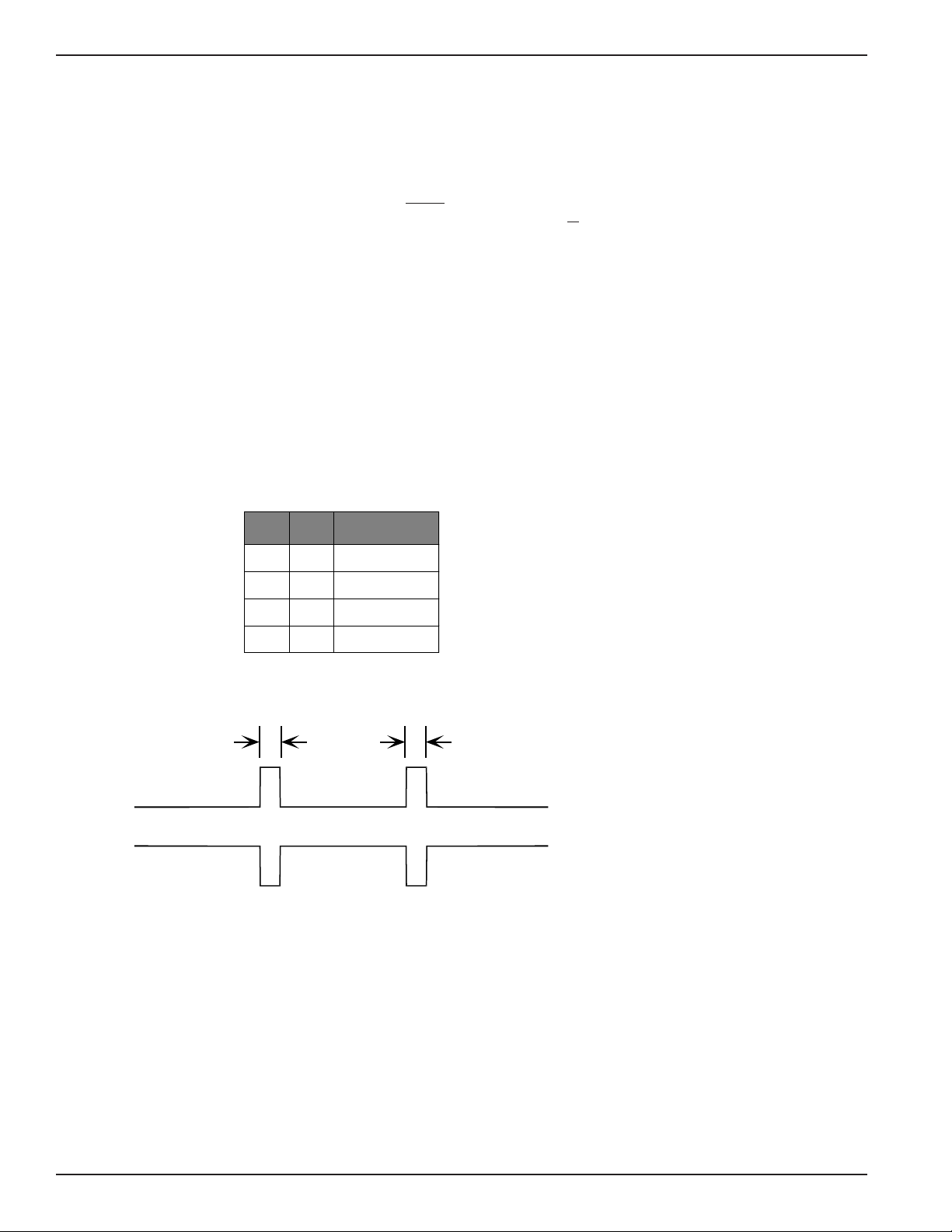
The 3028 Turbo (CTS 2031 Turbo) provides a Crypto Reset signal as an RS-232-C
signal indication on the Composite port.
The positive signal for Crypto Reset is provided on pin 11. The negative signal is
provided on pin 12 The Crypto reset pulse is 150ms in duration and occurs every
4, 8, 12 or 16 seconds as selected by jumpers J15 and J16 and the table below.
JP16 JP15 Time Delay
ON ON 4 Seconds
is
SUPERVISORSUPERVISOR
SUPERVISOR
SUPERVISORSUPERVISOR
ALARM SIGNALSALARM SIGNALS
ALARM SIGNALS
ALARM SIGNALSALARM SIGNALS
CRYPTO RESETCRYPTO RESET
CRYPTO RESET
CRYPTO RESETCRYPTO RESET
SIGNALSIGNAL
SIGNAL
SIGNALSIGNAL
YY
Y
YY
OFF ON 8 Seconds
ON OFF 12 Seconds
OFF OFF 16 Seconds
150mS
4, 8, 12 or 16
Seconds
Pin 11
Pin 12
The first pulse is sent after the Link Down indication has occured for the length
of time specified by the selection jumpers and continues to occur at the selected
interval until the link is operational once more.
150mS
20311-4
154001UA1-8
Page 14

2. Operation of the 3028 Turbo Multiplexer
2. Operation of the 3028 T2. Operation of the 3028 T
2. Operation of the 3028 T
2. Operation of the 3028 T2. Operation of the 3028 T
Overview ......................................................................................................................................... 2-2
Supervisory Function Overview ................................................................................................. 2-2
Front Panel Operation ...................................................................................................................2-3
Terminal Operation .......................................................................................................................2-5
Modes of Operation ....................................................................................................................... 2-5
Standby Mode/Logoff ................................................................................................................... 2-6
Monitor Mode ................................................................................................................................. 2-6
System Error Messages .........................................................................................................2-8
Monitor Mode Events ...........................................................................................................2-9
Memory Capability ..................................................................................................................... 2-10
Command Mode .......................................................................................................................... 2-10
Command Mode Definitions ............................................................................................ 2-11
Channel Parameters ........................................................................................................... 2-15
Channel Speed ........................................................................................................... 2-16
Channel Type ............................................................................................................. 2-19
Channel Data Bits ...................................................................................................... 2-20
Channel Stop Bits ...................................................................................................... 2-22
Channel Parity ........................................................................................................... 2-23
Channel Flow Control .............................................................................................. 2-25
Channel reverse Flow Control ................................................................................ 2-27
Channel Flow Control Translation ......................................................................... 2-29
Channel EIA Propagation ........................................................................................ 2-30
Channel Break Propagation ..................................................................................... 2-32
Channel Echoplex ..................................................................................................... 2-33
Channel Flyback Buffering ...................................................................................... 2-35
Channel CTS-RTS Control ....................................................................................... 2-36
Channel Messages Enabled ..................................................................................... 2-38
Channel Supervisor Enabled ................................................................................... 2-40
Channel Inactivity Disconnect ................................................................................ 2-42
Channel Disconnect Character ............................................................................... 2-43
Link Parameters .................................................................................................................. 2-46
Link Clock Source ..................................................................................................... 2-46
Link Clock Rate .......................................................................................................... 2-47
Supervisory Parameters .................................................................................................... 2-49
Copy Parameters ................................................................................................................ 2-51
Channel Statistics ............................................................................................................... 2-52
Link Statistics ...................................................................................................................... 2-55
Local Channel Loopback ................................................................................................... 2-58
Remote Channel Loopback ............................................................................................... 2-60
Local Link Loopback ......................................................................................................... 2-61
Channel Reset ..................................................................................................................... 2-62
Link Reset ............................................................................................................................ 2-63
Statistics Reset .................................................................................................................... 2-64
Channel Validate ................................................................................................................ 2-64
Channel Status .................................................................................................................... 2-66
Remote Signon .................................................................................................................... 2-68
Remote Signoff .................................................................................................................... 2-70
Set System Password ......................................................................................................... 2-71
Set System Banner .............................................................................................................. 2-72
Set System Time .................................................................................................................. 2-72
Disable/Enable Front Panel ............................................................................................. 2-73
Monitor Mode ..................................................................................................................... 2-74
Logoff ................................................................................................................................... 2-75
Resetting The Multiplexer ......................................................................................................... 2-75
urbourbo
urbo
urbourbo
MultiplexerMultiplexer
Multiplexer
MultiplexerMultiplexer
154001UA 2-1
Page 15

3028 Turbo Statistical Multiplexer
This chapter explains the different methods you can use to configure, monitor
and control the multiplexer operations. It provides step-by-step instructions for
each method and summary areas for quick reference.
When the multiplexer is attached to a DCX multiplexer, there are three ways to
operate the supervisory functions:
1. The front panel keys and LCD display.
2. A terminal connected to the supervisory port.
3. A terminal connected to any asynchronous channel port enabled for the
supervisory function.
4. A terminal connected via the DCX network to an enabled supervisor
channel.
When the multiplexer is being used in Point-to-Point applications, there are three
additional operating methods:
1. The remote front panel interface.
2. A terminal connected to a remote supervisory port.
OVERVIEWOVERVIEW
OVERVIEW
OVERVIEWOVERVIEW
SUPERVISORSUPERVISOR
SUPERVISOR
SUPERVISORSUPERVISOR
FUNCTIONFUNCTION
FUNCTION
FUNCTIONFUNCTION
OVERVIEWOVERVIEW
OVERVIEW
OVERVIEWOVERVIEW
YY
Y
YY
3. A terminal connected to a remote asynchronous channel port enabled for
the supervisory function.
NoteNote
Note
NoteNote
In general only one terminal, local or remote,
may be signed on as supervisor at the multiplexer
at any given time. Supervisory functions at the
front panel, however, may be carried on concurrently with a terminal supervisor.
Any of the terminals in Figure 2-1 may be used to access supervisory functions in
either 3028 Turbo (CTS 2031 Turbo). In addition, when the multiplexer is used in a
DCX network (Figure 2-1) any attached terminal can access the DCX supervisory
functions remotely. Refer to the DCX 850 Installation and Operation Manual, 2985-
A2-GN30, for procedures.
2-2 154001UA
Page 16
DCX 840/850
LSC ARQ ARQ
2. Operation of the 3028 Turbo Multiplexer
FRONT PANELFRONT PANEL
FRONT PANEL
FRONT PANELFRONT PANEL
OPERAOPERA
OPERA
OPERAOPERA
TIONTION
TION
TIONTION
STATISTICAL
MULTIPLEXER
POWER LOSS DOWN CONTROL
3028 Turbo
12345678SUPV
Figure 2-1. Remote Supervisory Access in a DCX Network ConfigurationFigure 2-1. Remote Supervisory Access in a DCX Network Configuration
Figure 2-1. Remote Supervisory Access in a DCX Network Configuration
Figure 2-1. Remote Supervisory Access in a DCX Network ConfigurationFigure 2-1. Remote Supervisory Access in a DCX Network Configuration
There are four push buttons on the front panel that can be used
to configure the multiplexer (Figure 2-2). These push buttons
are:
NEXT
LAST
SELECT
MON/CLR (Monitor/Clear)
12345678SUPV
3028 Turbo
30 28 T URBO
DATA LINK FLOW
Figure 2-2. Multiplexer Front PanelFigure 2-2. Multiplexer Front Panel
Figure 2-2. Multiplexer Front Panel
Figure 2-2. Multiplexer Front PanelFigure 2-2. Multiplexer Front Panel
NEXT LAST SEL MON/CL
20312- 1
20312-50
The functions of these push buttons are summarized in Table 21.
NoteNote
Note
NoteNote
Use of these push buttons in COMMAND
mode may be disabled if the front panel has
been disabled via the CRT Disable/Enable
Front Panel command.
154001UA 2-3
Page 17
3028 Turbo Statistical Multiplexer
g
g
g
g
g
g
g
g
g
ggreg
Table 2-1. Front Panel Push Button DescriptionsTable 2-1. Front Panel Push Button Descriptions
Table 2-1. Front Panel Push Button Descriptions
Table 2-1. Front Panel Push Button DescriptionsTable 2-1. Front Panel Push Button Descriptions
PUSH BUTTON DESCRIPTION
NEXT This push button allows entry into COMMAND mode (refer
LAST In COMMAND mode this push button is used to move to
SELECT This push button is used in COMMAND mode to enter the
MON/CLR This push button is used in COMMAND mode to exit a
to COMMAND MODE section) when the start-up messa
is displayed or the device is in MONITOR mode (refer to
MONITOR MODE section).
In COMMAND mode (COMMAND MODE displayed on the
first line of the LCD) this push button moves to the next
command. If the LCD displays a parameter (parameter
displayed on the first line of the LCD) this push button
causes the next parameter to appear. This push button
does not update the parameter.
the previous command, parameter or option dependin
the level of operation at any
does not update the parameter.
displayed parameter or update use of the selected option.
parameter without makin
COMMAND MODE / CHNL PARAMETERS display.
If you are already at the command prompt, this push button
lo
s off as supervisor and enters MONITOR mode. If this
push button is pressed while in MONITOR mode, the LCD
will display:
iven time. This push button
changes and return to the
on
e
This display will remain until the NEXT push button is
pressed to enter COMMAND mode or the MON/CLR push
The multiplexer has four LED displays on the front panel. Their functions are
described in Table 2-2.
Table 2-2. Panel LED DescriptionsTable 2-2. Panel LED Descriptions
Table 2-2. Panel LED Descriptions
Table 2-2. Panel LED DescriptionsTable 2-2. Panel LED Descriptions
LED DESCRIPTION
POWER This LED indicates that the power supply is operating. If
LINK DOWN This LED, when lit, indicates that the communication link
FLOW CONTROL This LED is turned on when buffer usage reaches 65%
DATA LOSS This LED is lit for ten seconds when data is lost or when
this LED does not li
has failed, when flashin
and is turned off when the total buffer usa
45%. These limits indicate the thresholds for potentially
invokin
or releasing channel flow control signals.
the a
ate input limit of 76.8Kbps has been exceeded.
ht and the system is plugged in, a
, indicates a loopback state.
e drops below
2-4 154001UA
Page 18

2. Operation of the 3028 Turbo Multiplexer
TERMINALTERMINAL
TERMINAL
TERMINALTERMINAL
OPERAOPERA
OPERA
OPERAOPERA
MODES OFMODES OF
MODES OF
MODES OFMODES OF
OPERAOPERA
OPERA
OPERAOPERA
TIONTION
TION
TIONTION
TIONTION
TION
TIONTION
Configuration of the multiplexer can be done through the use of an attached
terminal. The attached terminal can be any standard asynchronous terminal. A
series of screens enable you to configure the multiplexer. The keys available for
use are:
RETURN or ENTER
The RETURN or ENTER key is used to update the selected
option, to exit a menu without making changes, or to access the
Main Menu from MONITOR mode.
BACKSPACE or DELETE
The BACKSPACE or DELETE key is used to correct mistakes
during entry before pressing the RETURN key.
Number Keys
The number keys are used to select options from the menu
screens.
Front Panel
There are three modes of operation:
STANDBY MODE This mode displays the message SYSTEM READY
and the system clock.
MONITOR MODE This mode allows for the display of system
events.
COMMAND MODE This mode provides access to the supervisory
functions.
Terminal
There are three modes of operation:
LOGOFF This mode causes the terminal to display the
message SUPERVISOR LOGOFF @ hh:mm:ss
where hh:mm:ss is the current system time.
MONITOR MODE This mode allows for the display of system
events.
COMMAND MODE This mode provides access to the supervisory
functions.
154001UA 2-5
Page 19

3028 Turbo Statistical Multiplexer
When the multiplexer is in STANDBY mode, the system event displays are
stored and displayed when monitor mode is entered. The display that is shown
during the STANDBY mode is:
SYSTEM READY
00:00:00
20312-51
When the multiplexer terminal is in LOGOFF mode the terminal displays
SUPERVISOR LOGOFF @ hh:mm:ss where the time displayed is the current
system time. The terminal will remain logged off until the supervisor logon
character is pressed to enter COMMAND mode. From COMMAND mode,
changes to the parameters may be made or MONITOR mode can be entered.
When the multiplexer is in MONITOR mode the system displays the system
events as they occur. Entry into MONITOR mode also constitutes a supervi-
sory signoff allowing other channels access to the supervisory functions.
The first display after entering MONITOR mode is the current PROM level
installed (REV nnn.nn). After this, the events that have occurred are displayed.
The message queue holds 16 messages and after they are displayed they cannot
be recalled. The messages can be displayed on either the terminal or LCD,
whichever enters MONITOR mode first. If more than 16 messages occur, only
the latest 16 are kept to be displayed.
STST
ANDBY MODE/ANDBY MODE/
ST
ANDBY MODE/
STST
ANDBY MODE/ANDBY MODE/
LOGOFFLOGOFF
LOGOFF
LOGOFFLOGOFF
MONITOR MODEMONITOR MODE
MONITOR MODE
MONITOR MODEMONITOR MODE
Note
When you are signed on to a remote 3028
Turbo (CTS 2031 Turbo), the messages
displayed as remote events are actually local
events to your 3028 Turbo (CTS 2031 Turbo).
Front Panel Access
MONITOR mode is entered by pressing the MON/CLR push button once from
the STANDBY or COMMAND modes and by pressing the MON/CLR push
button twice from a command, parameter or option in COMMAND mode. The
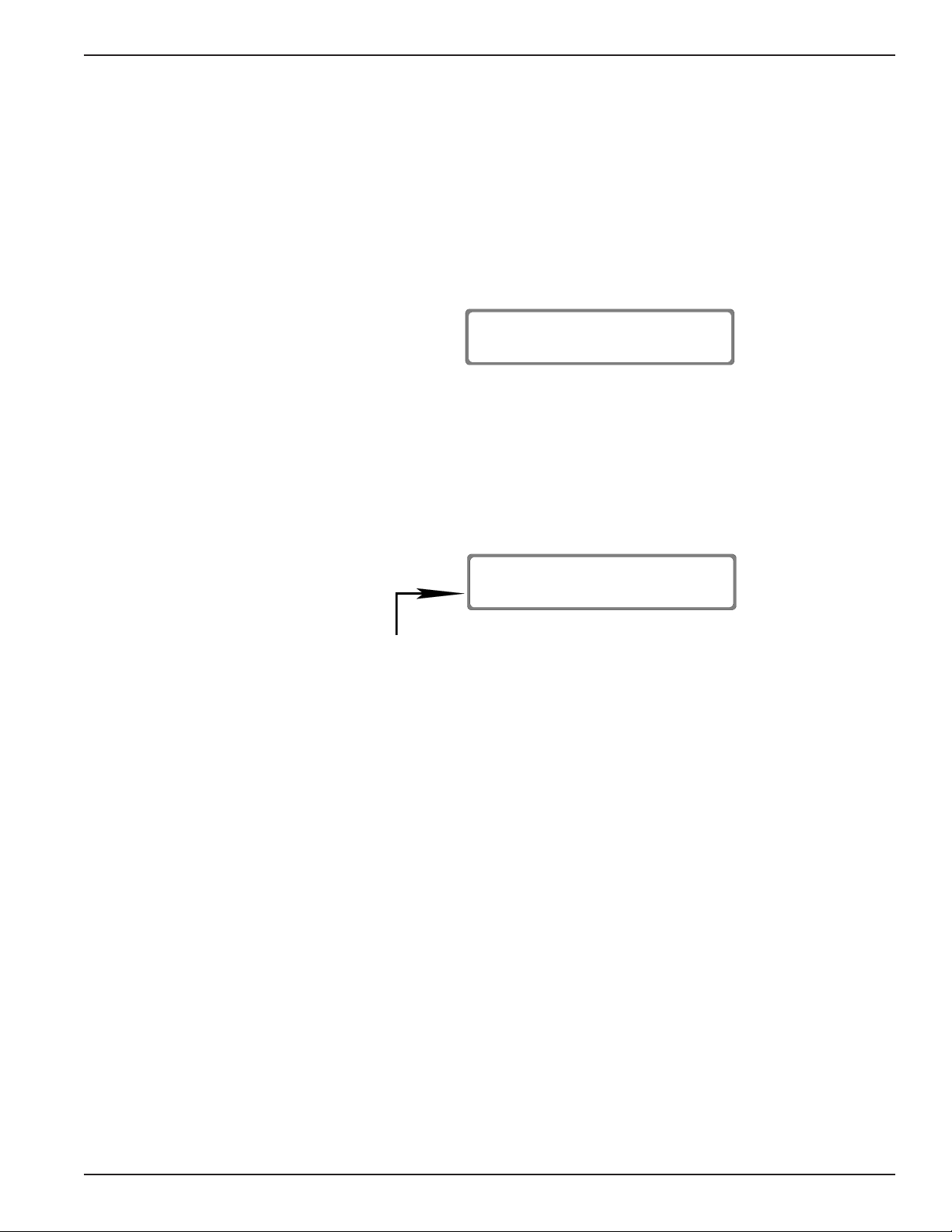
LCD will display the following until an event occurs for display.
When you enter MONITOR mode and there are events in the queue, they will
be displayed, earliest first, for a minimum of two seconds each.
In a point-to-point application, events are displayed at both the local and the
remote ends when each LCD is in the MONITOR mode (Figures 2-3 and 2-4).
The first line displays the time the event occurred and the second line displays
the event that occurred (Table 2-3). Events are displayed in the following format:
MONITOR MODE
REV 938 14.0
20312-52
2-6 154001UA
Page 20

-
3
EVENT @ 10:00:00
-
4
CHNL 1 RESET
Figure 2-3. Local Event DisplayFigure 2-3. Local Event Display
Figure 2-3. Local Event Display
Figure 2-3. Local Event DisplayFigure 2-3. Local Event Display
R EVT @ 10:00:00
CHNL 1 RESET
Figure 2-4. Remote Event DisplayFigure 2-4. Remote Event Display
Figure 2-4. Remote Event Display
Figure 2-4. Remote Event DisplayFigure 2-4. Remote Event Display
The multiplexer uses a 24-hour clock for
time displays and does not have the date
maintained as part of the time stamp.
Queued messages are deleted when the
system clock goes from 23:59:59 to
00:00:00.
2. Operation of the 3028 Turbo Multiplexer
20312-53
20312-54
Note
MONITOR MODE
REV 938 14.0
To enter STANDBY mode:
PRESS: MON/CLR
To enter COMMAND mode:
PRESS: NEXT
Terminal Access
To enter MONITOR mode from the terminal main menu:
TYPE: 22
PRESS: RETURN
The terminal indicates that MONITOR mode is entered with a screen display:
20312
When an event occurs (Figure 2-5) it is displayed on the terminal:
MONITOR MODE
EVENT @ 10:00:00 event
REMOTE EVENT @ 10:00:00 event
Figure 2-5. Event MessagesFigure 2-5. Event Messages
Figure 2-5. Event Messages
Figure 2-5. Event MessagesFigure 2-5. Event Messages
20312
154001UA 2-7
Page 21

3028 Turbo Statistical Multiplexer
To enter COMMAND mode ,
PRESS: <supervisor logon character>
(default = CTRL + V)
If the password protection is in use, you are prompted to enter the correct
password. Enter the password and press RETURN; the Main Menu will then
be displayed.
The SYSTEM ERROR message displayed in diagnostic failure at start-up pro-
vides information as to the type of failure detected. The format of the informa-
tion is as follows:
SYSTEM ERROR n
20312-55
Where n is one of the following:
M - EPROM checksum failed., U41 & U42
A - memory A000-AFFF failed, RAM U40
B - memory B000-BFFF failed, RAM U40
C - memory C000-CFFF failed, RAM U39
D - memory D000-DFFF failed, RAM U39
E - memory E000-EFFF failed, RAM U38
F - memory F000-FFFF failed, RAM U38
1 - Port 1 or Supervisory Port failed - SCC U29 or U33
2 - Port 2 failed - SCC U29
3 - Port 3 failed - SCC U30
4 - Port 4 failed - SCC U30
5 - Port 5 failed - SCC U31
6 - Port 6 failed - SCC U31
7 - Port 7 failed - SCC U32
8 - Port 8 failed - SCC U32
The order of testing is as listed above. Any one failure will terminate testing.
System ErrorSystem Error
System Error
System ErrorSystem Error
MessagesMessages
Messages
MessagesMessages
2-8 154001UA
Page 22

2. Operation of the 3028 Turbo Multiplexer
g
g
g
g
g
g
g
g
gg
gg
Monitor Mode EventsMonitor Mode Events
Monitor Mode Events
Monitor Mode EventsMonitor Mode Events
Table 2-3 lists the MONITOR mode events.
Table 2-3. MONITOR Mode EventsTable 2-3. MONITOR Mode Events
Table 2-3. MONITOR Mode Events
Table 2-3. MONITOR Mode EventsTable 2-3. MONITOR Mode Events
EVENT DESCRIPTION
CHNL n RESET* This event indicates that the indicated channel has
CHNL n FL CTL* This event reports that flow control was invoked for the
CHNL n RV FL CTL* This event indicates that a preprogrammed reverse
CHNL n ACTIVE* This event indicates that the flow control or reverse
CHNL n LOOPED* This event indicates that the channel has been put in a
LINK FAILED This event indicates that a link interface is no longer
LINK # CHL INV This event reports that the remote multiplexer has more
been reset, locally or remotely, via the terminal or front
panel interface. The reset function clears the data
buffers and resets any flow control or reverse flow
control states at each end.
indicated channel in response to either the channel
exceedin
the channel speed) or the total system buffer utilization
reachin
locally only).
flow control si
indicated channel, causin
transmission temporarily (reported locally only).
flow control condition has cleared at the indicated
channel throu
command) (reported locally only).
loopback condition, where the data sent to the channel
both inward and outward is looped back.
recevin
is
fails. A failure is declared after approximately 10
seconds of noncommunication and retries (reported
locally only).
its flow control level (the percent is based on
65% of the multiplexer capacity (reported
nal has been received from the
the multiplexer to suspend
h normal means (not a Channel RESET
acknowledgements to its transmissions. This
enerated only when a link that has been operational
CHNL n DATA LOSS* This event reports that user channel data has been
LINK ESTABLISHED This event reports that a link has been established and
SUPVR SIGNON This event reports that a local or remote supervisor has
SUPVR SIGNOFF This event reports that a local or remote supervisor has
*n = the channel on which the event occurs.
lost.
communication can be
to reestablish itself; if it is successful, this event
occurs(reported locally only).
lo
ed on.
lo
ed off.
in. A failed link continually tries
154001UA 2-9
Page 23

3028 Turbo Statistical Multiplexer
The 3028 Turbo (CTS 2031 Turbo) has sufficient nonvolatile memory so that certain
operating parameters will be retained through a power loss. The following will be
maintained through a power-off, power-on sequence:
Channel parameters
Supervisory port parameters
Link parameters
System password
System banner (part of Main Menu)
Any front panel inhibited status
Any forced EIA output signals
The following are not maintained through a power-off, power-on sequence, but are
"cleared" upon system restart:
Peak channel and link usage statistics
System time
Any flow control or reverse flow control XOFF states
Any channel loopbacks
Link loopbacks
Detected autobaud speeds
Propagated EIA signals
Monitor messages
MEMORMEMOR
MEMOR
MEMORMEMOR
CAPCAP
ABILITYABILITY
CAP
ABILITY
CAPCAP
ABILITYABILITY
YY
Y
YY
Command mode allows the operator to configure the multiplexer for operation
using either the multiplexer front panel or an attached terminal.
Front Panel Access
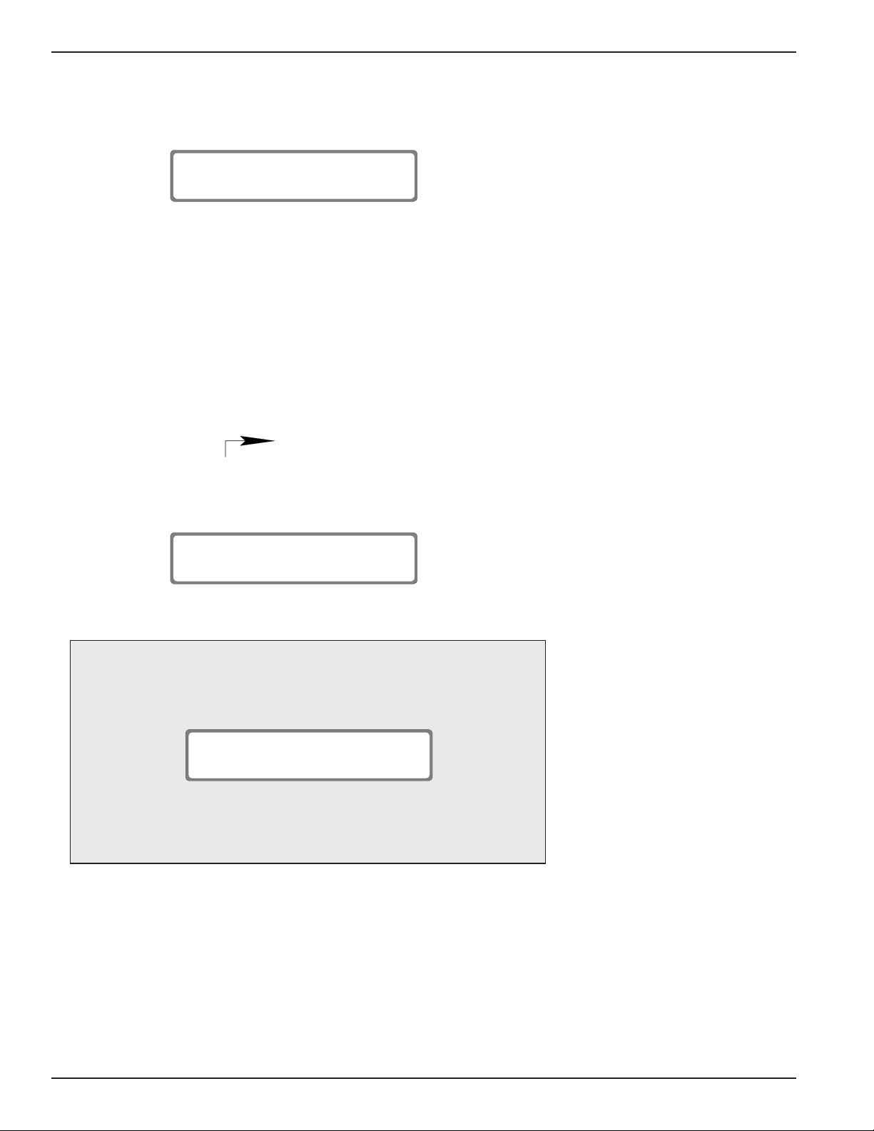
The NEXT push button accesses Command mode from Monitor mode or Standby
mode. The LCD will Display
COMMAND MODE
CHNL PARAMETERS
20312-56
SUPERVISOR BUSY displays when an attempt is made to sign on to a remote 3028
Turbo (CTS 2031 Turbo) that has a front panel already in use.
SUPERVISOR BUSY
20312-57
COMMAND MODECOMMAND MODE
COMMAND MODE
COMMAND MODECOMMAND MODE
2-10 154001UA
Page 24

Terminal Access
0312-
5
At initial logon or from MONITOR MODE
PRESS: <supervisor logon character>
If a password entry is needed, you are prompted to enter the password. After
doing this the Main Menu (figure 2-6) displays:
S Y S T E M M E N U
1.
SET CHANNEL PARAMETERS
2.
SET LINK PARAMETERS
3.
SET SUPERVISORY PARAMETERS
4.
COPY PARAMETERS
5.
CHANNEL STATISTICS
6.
LINK STATISTICS
7.
SET/CLEAR LOCAL CHANNEL LOOPBACK
8.
SET/CLEAR REMOTE CHANNEL LOOPBACK
9.
LOCAL LINK LOOPBACK
10.
RESET A SINGLE CHANNEL
11.
RESET ALL CHANNELS
12.
RESET LINK
(default = CTRL + V)
13.
14.
15.
16.
17.
18.
19.
20.
21.
22.
23.
2. Operation of the 3028 Turbo Multiplexer
RESET STATISTICS
CHANNEL VALIDATE
CHANNEL STATUS
REMOTE SIGNON
REMOTE SIGNOFF
SET SYSTEM PASSWORD
SET SYSTEM BANNER
SET SYSTEM TIME
DISABLE/ENABLE FRONT PANEL
ENTER MONITOR MODE
LOGOFF
Command ModeCommand Mode
Command Mode
Command ModeCommand Mode
DefinitionsDefinitions
Definitions
DefinitionsDefinitions
ENTER 1-23 <CR> TO SELECT DESIRED FUNCTION:
Figure 2-6. Command Mode Main MenuFigure 2-6. Command Mode Main Menu
Figure 2-6. Command Mode Main Menu
Figure 2-6. Command Mode Main MenuFigure 2-6. Command Mode Main Menu
If the Main Menu does not appear, check to make sure the SUPERVISOR
ENABLED parameter is set to YES (refer to Channel Supervisor Enabled
paragraph).
If the supervisor is currently in use, the message SUPERVISOR BUSY is
returned.
LCD
The LCD display is made up of 2 lines with 16 character positions on each line.
An asterisk (*) before the channel number selection (Figure 2-7) indicates the
current selection. Use the NEXT or LAST push button to move the asterisk to
the next or previous option, respectively.
SELECT CHANNEL:
2
*1 2 3 4 5 6 7 8
20312-58
Figure 2-7. Asterisk Position ExampleFigure 2-7. Asterisk Position Example
Figure 2-7. Asterisk Position Example
Figure 2-7. Asterisk Position ExampleFigure 2-7. Asterisk Position Example
154001UA 2-11
Page 25
3028 Turbo Statistical Multiplexer
A number sign (#) in the first position of the second line (Figure 2-8) indicates the
current value for the parameter.
CHNL n SPEED
# 7200
20312-59
Figure 2-8. Number Sign Position ExampleFigure 2-8. Number Sign Position Example
Figure 2-8. Number Sign Position Example
Figure 2-8. Number Sign Position ExampleFigure 2-8. Number Sign Position Example
An n in a display will be replaced by the channel number selected.
Use the NEXT and LAST push buttons to move forward or backward through
the commands, parameters or options.
When pressed, the SELECT push button either moves from a command to a
parameter, a parameter to an option or updates the selected option.
The displays and screens shown are samples and do not necessarily reflect your
configuration.
In this chapter, the symbol indicates that the values following will
appear on the second line of the display.
The starting point for accessing commands and parameters described in this
chapter is the COMMAND MODE display (Figure 2-9).
COMMAND MODE
CHNL PARAMETERS
20312-60
Figure 2-9. Command Mode DisplayFigure 2-9. Command Mode Display
Figure 2-9. Command Mode Display
Figure 2-9. Command Mode DisplayFigure 2-9. Command Mode Display
Note
When a parameter is selected to change a particular channel, you
receive the following display prior to access of the options.
SELECT CHANNEL:
*1 2 3 4 5 6 7 8
The commands that require channel selection are indicated in Table 2-4
by a double asterisk (**) following the command name. Factory set
defaults are listed first in the options/notes column.
Terminal Access
20312-58
The terminal screen does not clear after selection of a command or parameter.
It scrolls the selected option information onto the bottom of the screen. For
display purposes, the screen in the following paragraphs shows only the infor-
mation for the selection and not the information that will appear above that on
your screen.
2-12 154001UA
Page 26
2. Operation of the 3028 Turbo Multiplexer
The BACKSPACE or DELETE keys can be used to erase an incorrect entry
before pressing RETURN.
The following paragraphs describe access of the commands and parameters
(Table 2-4) from both the front panel and an attached terminal.
Note
When a parameter is selected to change a particular channel, you
receive the following display prior to access of the options.
SELECT CHANNEL NUMBER (1-8) <CR>:
2031N-1
The commands that require channel selection are indicated in Table 2-4
by a double asterisk (**) following the command name. Factory set
defaults are listed first in the options/notes column.
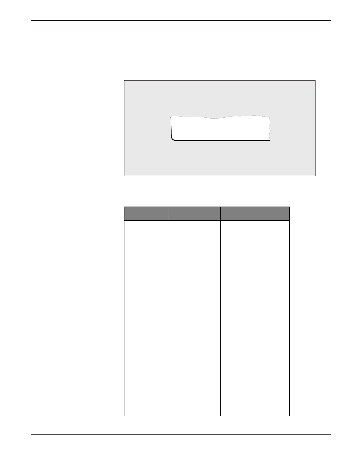
Table 2-4. Commands, Parameters and Options (1 of 2)Table 2-4. Commands, Parameters and Options (1 of 2)
Table 2-4. Commands, Parameters and Options (1 of 2)
Table 2-4. Commands, Parameters and Options (1 of 2)Table 2-4. Commands, Parameters and Options (1 of 2)
COMMAND PARAMETER OPTIONS/NOTES
CHNL
PARAMETERS**
SPEED 9600, 19,200, DOWNL,
AUTOB, 50, 75, 110, 134, 150,
300, 600, 1200, 1800, 2000,
2400, 3600, 4800, 7200
TYPE ASYNC, HPENQ, SDLC/HDLC
DATA BITS 8, 7, 6, 5
STOP BITS 1, 1.5, 2
PARITY NONE/SPACE, NONE/ODD,
NONE/EVEN, ODD, EVEN,
NONE/MARK
FL CTL DC3/DC1, DC2/DC1, DC4/DC2,
USER, WANG®, TANDEM®,
CTS-/CTS+, DSR-/DSR+,
NONE
FL CTL TR NO, YES
RV FL CTL NONE, DC3/DC1, DC2/DC1,
DC4/DC2, USER, WANG®,
RTS-/RTS+, DTR-/DTR+
EIA PROP NO, YES
BRK PROP NO, YES
ECHOPLEX NO, YES
FLYBACK NO, YES
CTS-RTS NO, YES
MSGS ENAB NO, YES
SPVR ENAB NO, YES
INAC DISC NO, YES
DISC CHAR CTL-T, NONE, USER
154001UA 2-13
Page 27
3028 Turbo Statistical Multiplexer
Table 2-4. Commands, Parameters and Options (2 of 2)Table 2-4. Commands, Parameters and Options (2 of 2)
Table 2-4. Commands, Parameters and Options (2 of 2)
Table 2-4. Commands, Parameters and Options (2 of 2)Table 2-4. Commands, Parameters and Options (2 of 2)
COMMAND PARAMETER OPTIONS/NOTES
LINK LINK CLK SOURCE EXTERN, INTERN
PARAMETERS LINK CLK RATE 9600, 7200, 4800, 3600, 2400,
COPY
PARAMETERS**
CHANNEL
STATISTICS
LINK STATISTICS FR RECD nnn CURR
CHANNEL
STATUS**
LOCAL CHANNEL
LOOPBACK**
REMOTE
CHANNEL
LOOPBACK**
LINK LOOPBACK
CHANNEL
RESET**
LINK RESET
CHANNEL
VALIDATE**
STATISTICS
RESET
REMOTE SIGNON not available in remote
REMOTE SIGNOFF
SET TIME 00:00:00 set time according to a 24-hour
COPY FROM
COPY TO
BF UTIL nn% CURR
BF UTIL nn% PEAK
EXC nnnn FC nnnn
RV FC nnnn
FR RECD nnn PEAK
FR NAKD nnn CURR
FR NAKD nnn PEAK
FR RSNT nnn CURR
FR RSNT nnn PEAK
TX UTIL nn% CURR
TX UTIL nn% PEAK
RX UTIL nn% CURR
RX UTIL nn% PEAK
DRS xxx BO xxx
DTR xxx RTS xxx
CTS xxx RI xxx
DCD xxx DSR xxx
LLB xxx RLB xxx
FC xxx RFC xxx
ACTIVITY zzz
1200, 19,200.
select channel (1-8).
select channel (1-8 or ALL).
nn is the percentage of
utilization, nnnn is the number
of occurences.
nn is the percentage of
utilization, nnn is the number of
occurences.
xxx is ON or OFF,
zzz is YES or NO.
select channel (1-8).
select channel (1-8), not
available in remote supervisor
mode.
select channel (1-8 or ALL).
select channel (1-8 or
supervisor).
supervisor mode.
clock.
2-14 154001UA
Page 28
2. Operation of the 3028 Turbo Multiplexer
Channel ParametersChannel Parameters
Channel Parameters
Channel ParametersChannel Parameters
The CHANNEL PARAMETERS command is used to change or examine any of
17 programmable parameters on any of the available channel ports or the
supervisory port.
Front Panel Access
From the COMMAND MODE / CHANNEL PARAMETER display:
PRESS: SELECT
The LCD Displays:
SELECT CHANNEL:
*1 2 3 4 5 6 7 8
20312-58
PRESS: NEXT or LAST
to select a channel
PRESS: SELECT
The asterisk (*) before the channel number indicates the channel which is
accessed.
The LCD will now display:
CHNL PARAMETERS
Where is CHNL n SPEED
CHNL n TYPE
CHNL n DATA BITS
CHNL n STOP BITS
CHNL n PARITY
CHNL n FL CTL
CHNL n RV FL CTL
CHNL n FL CTL TR
CHNL n EIA PROP
20312-61
CHNL n BRK PROP
CHNL n ECHOPLEX
CHNL n FLYBACK
CHNL n CTS-RTS
CHNL n MSGS ENAB
CHNL n SPVR ENAB
CHNL n INAC DISC
CHNL n DISC CHAR
154001UA 2-15
Page 29

3028 Turbo Statistical Multiplexer
Terminal Access
To select the CHANNEL PARAMETERS screen:
TYPE: 1
PRESS: RETURN
A channel must be selected following the display:
SELECT CHANNEL NUMBER (1-8) <CR>
After a channel is selected the terminal displays:
20312-6
1.
SPEED: 9600
2.
TYPE: ASYNC
3.
DATA BITS: 8
4.
STOP BITS: 1
5.
PARITY: NONE/SPACE
(ENTER 1-17 <C R> TO SELECT A PARAMETER, OR <CR> TO QUIT.):
6.
FLOW CTL
(XOFF/XON):
DC3/DC1
REV FL CTL:
7.
NONE
8.
FL CTL TR: NO
9.
EIA PROP: NO
10.
BREAK: NO
11.
ECHO: NO
12.
FLYBK: NO
13.
CTS-RTS: NO
14.
MSGS ENAB: NO
15.
SUPERV ENAB: NO
16.
INACT DISC: NO
17.
DISC CHAR: CTL-T
The SPEED parameter sets the data rate for the Channel port. There are 16
speeds to choose from, or the channel may be set to detect the speed of the
incoming characters and adjust itself appropriately using AUTOBAUD options.
The AUTOBAUD option will not trigger on the following speeds: 19.2K, 134.5,
110, 75 and 50. The remote end channel, when set to DOWNL, receives the
setting and is also adjusted to the detected speed. The AUTOBAUD option is
used when data transmission rates vary or are unknown such as with asynchro-
nous modem tail circuits. To use the AUTOBAUD option, turn the attached
terminal on, then enter a CARRIAGE RETURN. Cycling the power is neces-
sary since an off-to-on transition on DTR is required to trigger the multiplexer
to look for the AUTOBAUD character. (Note that this will be DSR OFF-to-ON if
a standard crossover cable is used on a modem tail circuit.)
20312-7
Channel SpeedChannel Speed
Channel Speed
Channel SpeedChannel Speed
If the speed is detected, the following display appears on an attached terminal
(if available):
AUTOBAUD SPEED DETECTED: nnnn
20312-8
2-16 154001UA
Page 30

2. Operation of the 3028 Turbo Multiplexer
If the message is received but is garbled, either the speed was incorrectly
determined or the parity is in error. To use the built in auto-parity function to
set the parity, enter the following immediately after the AUTOBAUD SPEED
DETECTED message.
TYPE: P (capital)
PRESS: RETURN
The multiplexer will set the parity based on the P and RETURN characters
received.
Note
All channels can be set to the 19,200 speed option as
long as the maximum aggregate input does not exceed
76,800bps. Exceeding the 76,800bps input may cause
data loss. Enabling certain channel parameters can
affect the aggregate input limit. Enabling the following
channel parameters will reduce the maximum aggregate input rate supported on the multiplexer: In-Band
Reverse Flow Control, Echoplex, Supervisor Enabled,
and Flyback Buffering. This is caused by the requirement to examine every character of data generated by
the terminal to the multiplexer.
Front Panel Access
From the COMMAND mode display:
PRESS: NEXT or LAST
until CHNL PARAMETERS displays on the second line
PRESS: SELECT
PRESS: NEXT or LAST
to choose a channel number
PRESS: SELECT
PRESS: NEXT or LAST
until CHNL n SPEED displays on the second line
PRESS: SELECT
154001UA 2-17
Page 31

3028 Turbo Statistical Multiplexer
the LCD displays:
CHNL n SPEED
20312-62
Where is 9600
19200
DOWNL
AUTOB
50
75
PRESS: NEXT or LAST
until the desired option displays
PRESS: SELECT
The multiplexer updates the channel speed and returns the CHNL PARAM-
ETERS/CHNL TYPE display.
Update the channel type,
110
134
150
300
600
1200
1800
2000
2400
3600
4800
7200
PRESS: MON/CLR
to exit, or
PRESS: NEXT or LAST
to go to another parameter
Terminal Access
From the Main Menu:
TYPE: 1
PRESS: RETURN
TYPE: n (n= channel number)
PRESS: RETURN
TYPE: 1
from the CHANNEL PARAMETERS menu
PRESS: RETURN
The terminal displays:
CHANNEL n SPEED: C URRENTLY: 9600
1:
19200
2:
9600
3:
7200
(ENTER 1-18 <CR> TO CHANGE. <CR> TO RETAIN OL D SETTING.):
4:
5:
6:
4800
3600
2400
7:
8:
9:
2000
1800
1200
10:
11:
12:
600
300
134.5
13:
14:
15:
150
110
75
16:
17:
18:
50
DOWNL
AUTOB
20312-9
2-18 154001UA
Page 32

2. Operation of the 3028 Turbo Multiplexer
TYPE: n (n = the speed option number)
PRESS: RETURN
The multiplexer updates the channel speed and returns the CHANNEL PA-
RAMETERS menu. If the RETURN key is pressed without entering a speed
option, the Main Menu is returned.
Channel TypeChannel Type
Channel Type
Channel TypeChannel Type
The TYPE parameter allows you to select a standard asynchronous data stream
or a channel with special protocol handling. The HPENQ option selects a set of
functions to improve throughput for terminals and CPUs observing the
Hewlett-Packard ENQ/ACK® block mode protocol. Appendix E provides
information on the Hewlett-Packard ENQ/ACK
option is described in Appendix I.
Front Panel Access
From the COMMAND MODE display:
PRESS: NEXT or LAST
until CHNL PARAMETERS displays on the second line
PRESS: SELECT
PRESS: NEXT or LAST
to choose a channel number
PRESS: SELECT
PRESS: NEXT or LAST
until CHNL n TYPE displays on the second line
PRESS: SELECT
the LCD displays:
®
protocol. The SDLC/HDLC
CHNL n TYPE
20312-63
Where is ASYNC
HPENQ
SDLC/HDLC
PRESS: NEXT or LAST
until the desired option displays
PRESS: SELECT
The multiplexer updates the channel type and returns the CHNL PARAM-
ETERS/CHNL DATA BITS display.
Update the channel data bits,
PRESS: MON/CLR
to exit, or
PRESS: NEXT or LAST
to go to another parameter
154001UA 2-19
Page 33

3028 Turbo Statistical Multiplexer
Terminal Access
To access the TYPE parameter from the Main Menu:
TYPE: 1
PRESS: RETURN
TYPE: n (n = channel number)
PRESS: RETURN
TYPE: 2
from the CHANNEL PARAMETERS menu
PRESS: RETURN
The terminal displays:
CHANNEL n TYPE: CURRENTLY: ASYNC
1: 2:ASYNC HPENQ 3: SDLC/HDLC
(ENTER 1-3 <C R> TO CHANGE. <CR> TO RETAIN OLD SETTING.):
TYPE: n (n = the channel type option number)
PRESS: RETURN
The multiplexer updates the channel type and returns the CHANNEL PARAM-
ETERS menu. If the RETURN key is pressed without entering a type option,
the Main Menu is returned.
The DATA BITS parameter establishes the number of data bits (excluding any
parity) between the start and stop bits of the character.
Front Panel Access
From the COMMAND MODE display
PRESS: NEXT or LAST
until CHNL PARAMETERS displays on the second line
PRESS: SELECT
PRESS: NEXT or LAST
to choose a channel number
20312-10
Channel Data BitsChannel Data Bits
Channel Data Bits
Channel Data BitsChannel Data Bits
PRESS: SELECT
PRESS: NEXT or LAST
until CHNL n DATA BITS displays on the second line
PRESS: SELECT
2-20 154001UA
Page 34

2. Operation of the 3028 Turbo Multiplexer
312-1
1
the LCD displays:
CHNL n DATA BITS
20312-64
Where is 8
7
6
5
PRESS: NEXT or LAST
until the desired option displays
PRESS: SELECT
The multiplexer updates the channel data bits and returns the CHNL PARAM-
ETERS/CHNL STOP BITS display.
Update the channel stop bits,
PRESS: MON/CLR
to exit, or
PRESS: NEXT or LAST
to go to another parameter
Terminal Access
To access the DATA BITS parameter from the Main Menu:
TYPE: 1
PRESS: RETURN
TYPE: n (n = channel number)
PRESS: RETURN
TYPE: 3
from the CHANNEL PARAMETERS menu
PRESS: RETURN
The terminal displays:
CHANNEL n DATA BITS: CURRENTLY: 8
1: 2:8 7 3: 4:65
(ENTER 1-4 <CR> TO CHANGE. <CR> TO RETAIN OL D SETTING.):
20
TYPE: n (n = the data bit option number)
PRESS: RETURN
The multiplexer updates the channel data bits and returns the CHANNEL
PARAMETERS menu. If the RETURN key is pressed without entering a data
bits option, the Main Menu is returned.
154001UA 2-21
Page 35

3028 Turbo Statistical Multiplexer
The STOP BITS parameter establishes the number of stop bits generated for an
outgoing asynchronous character. For incoming characters to the 3028 Turbo (CTS
2031 Turbo) this parameter is not critical since only one stop bit is looked for. Some
terminals, however, will not operate correctly unless two stop bits are appended to
each character sent toward them. Stop bits are not transmitted across the compos-
ite link.
Front Panel Access
From the COMMAND MODE display
PRESS: NEXT or LAST
until CHNL PARAMETERS displays on the second line
PRESS: SELECT
PRESS: NEXT or LAST
to choose a channel number
PRESS: SELECT
PRESS: NEXT or LAST
until CHNL n STOP BITS displays on the second line
PRESS: SELECT
the LCD displays:
Channel Stop BitsChannel Stop Bits
Channel Stop Bits
Channel Stop BitsChannel Stop Bits
CHNL n STOP BITS
20312-65
Where is 1
1.5
2
PRESS: NEXT or LAST
until the desired option displays
PRESS: SELECT
The multiplexer updates the channel stop bits and returns the CHNL PARAM-
ETERS/CHNL PARITY BITS display.
Update the channel parity bits,
PRESS: MON/CLR
to exit, or
PRESS: NEXT or LAST
to go to another parameter
2-22 154001UA
Page 36

Terminal Access
312-1
2
To access the STOP BITS parameter from the Main Menu:
TYPE: 1
PRESS: RETURN
TYPE: n (n = channel number)
PRESS: RETURN
TYPE: 4
from the CHANNEL PARAMETERS menu
PRESS: RETURN
The terminal displays:
CHANNEL n STOP BITS: CURRENTLY: 1
1: 2:1 1.5 3: 2
2. Operation of the 3028 Turbo Multiplexer
Channel ParityChannel Parity
Channel Parity
Channel ParityChannel Parity
(ENTER 1-3 <CR> TO CHANGE. <CR> TO RETAIN OL D SETTING.):
20
TYPE: n (n = the stop bit option number)
PRESS: RETURN
The multiplexer updates the channel stop bits and returns the CHANNEL PARAM-
ETERS menu. If the RETURN key is pressed without entering a stop bit option, the
Main Menu is returned.
The PARITY parameter controls whether or not a parity bit , in addition to the data
bits, is checked on incoming characters and appended on outgoing characters.
If you do not want the multiplexer to be sensitive to parity, the NONE/ODD,
NONE/EVEN, NONE/MARK or NONE/SPACE option should be chosen. The
NONE portion of the selection disables parity checking/insertion. The ODD,
EVEN, MARK or SPACE portion of the selections refers to the parity setting of the
3028 Turbo (CTS 2031 Turbo) generated messages such as Menus, LINK DOWN or
DATA LOSS. The MESSAGES ENABLED parameter must be set to YES before
messages are sent to the attached device.
When the ODD or EVEN option is selected and a parity error is detected, parity is
stripped and the character is sent as received to the remote end. A parity error
count is maintained in the channel statistics under CHANNEL EXCEPTIONS.
Appendix D provides more information on parity.
Front Panel Access
154001UA 2-23
Page 37

3028 Turbo Statistical Multiplexer
From the COMMAND MODE display
PRESS: NEXT or LAST
until CHNL PARAMETERS displays on the second line
PRESS: SELECT
PRESS: NEXT or LAST
to choose a channel number
PRESS: SELECT
PRESS: NEXT or LAST
until CHNL n PARITY displays on the second line
PRESS: SELECT
the LCD displays:
CHNL n PARITY
20312-66
Where is NONE/ODD
NONE/EVEN
ODD
EVEN
NONE/MARK
NONE/SPACE
PRESS: NEXT or LAST
until the desired option displays
PRESS: SELECT
The multiplexer updates the channel parity and returns the CHNL PARAMETERS/
CHNL FL CTL display.
Update the channel flow control,
PRESS: MON/CLR
to exit, or
PRESS: NEXT or LAST
to go to another parameter
Terminal Access
To access the PARITY parameter from the Main Menu:
TYPE: 1
PRESS: RETURN
TYPE: n (n = channel number)
PRESS: RETURN
2-24 154001UA
Page 38

TYPE: 5
312-1
3
from the CHANNEL PARAMETERS menu
PRESS: RETURN
The terminal displays:
TYPE: n (n = the parity option number)
CHANNEL n PARITY: CURRENTLY: NONE/ODD
2. Operation of the 3028 Turbo Multiplexer
1:
2:
(ENTER 1-6 <CR> TO CHANGE. <CR> TO RETAIN OL D SETTING.):
Channel Flow ControlChannel Flow Control
Channel Flow Control
Channel Flow ControlChannel Flow Control
NONE/ODD
NONE/SPACE
The multiplexer updates the channel parity and returns the CHANNEL PARAM-
ETERS menu. If the RETURN key is pressed without entering a parity option, the
Main Menu is returned.
The FLOW CONTROL parameter, also known as buffer overflow protection, is
a means of preventing data loss in high-traffic periods. Some terminals respond
to ASCII control characters (most commonly Device Control 1 and Device
Control 3 [DC1/DC3]) as signals to suspend and resume transmission. Others
respond to changes in the RS-232-C leads (most commonly CTS). Options
supported provide these and other possibilities, including any user-specified
character as either the XOFF (turning the data transmission off) or the XON
(turning the data transmission on) signal.
The USER option allows entry of arbitrary XON and XOFF characters. After
selection of the USER option, the current setting is displayed. Enter the revised
setting in decimal (0-255), allowing any of the 128 ASCII characters with either
parity setting. Entry of 255 and 0 are interpreted the same by the multiplexer.
3:
NONE/EVEN
4:
ODD
PRESS: RETURN
5:6:NONE/MARK
EVEN
20
Appendix F provides information on the TANDEM T-Pause® and Wang® flow
control methods.
Appendix J provides information on the EIA Signal Exceptions.
Note
Forcing an EIA signal high or low using the
CHANNEL STATUS command prevents
using that signal as a flow control option.
154001UA 2-25
Page 39

3028 Turbo Statistical Multiplexer
Front Panel Access
From the COMMAND MODE display
PRESS: NEXT or LAST
until CHNL PARAMETERS displays on the second line
PRESS: SELECT
PRESS: NEXT or LAST
to choose a channel number
PRESS: SELECT
PRESS: NEXT or LAST
until CHNL n FL CTL displays on the second line
PRESS: SELECT
the LCD displays:
CHNL n FL CTL
20312-67
Where is NONE
DC3/DC1
DC2/DC1
DC4/DC2
WANG
TANDEM
CTS-/CTS+
DSR-/DSR+
USER
PRESS: NEXT or LAST
until the desired option displays
PRESS: SELECT
The multiplexer updates the channel flow control and returns the CHNL
PARAMETERS/CHNL RV FL CTL display.
Update the channel Reverse Flow Control,
PRESS: MON/CLR
to exit, or
PRESS: NEXT or LAST
to go to another parameter
Terminal Access
To access the FLOW CONTROL parameter from the Main Menu:
TYPE: 1
PRESS: RETURN
TYPE: n (n = channel number)
PRESS: RETURN
TYPE: 6
2-26 154001UA
Page 40

2. Operation of the 3028 Turbo Multiplexer
312-1
4
from the CHANNEL PARAMETERS menu
PRESS: RETURN
The terminal displays:
CHANNEL n FLOW CTL: CURRENTLY: DC3/DC1 (XOFF/XON)
1:
2:
3:
(ENTER 1-9 <CR> TO CHANGE. <CR> TO RETAIN OLD SETTING.):
Channel Reverse FlowChannel Reverse Flow
Channel Reverse Flow
Channel Reverse FlowChannel Reverse Flow
ControlControl
Control
ControlControl
NONE
DC3/DC1
DC2/DC1
4:
5:
6:
DC4/DC2
USER
WANG
7:
TANDEM
8:
CTS-/CTS+
9:
DSR-/DSR+
20
TYPE: n (n = the flow control option number)
PRESS: RETURN
The multiplexer updates the channel flow control and returns the CHANNEL
PARAMETERS menu. If the RETURN key is pressed without entering a flow
control option, the Main Menu is returned.
The REVERSE FLOW CONTROL parameter, also known as terminal flow
control, establishes signals to suspend and resume output to attached peripher-
als. Reverse flow control is similar to flow control, except that it goes in the
other direction, i.e. from the terminal or host to the multiplexer.
When a terminal raises a reverse flow control signal, the remote end is notified
via an internal control message so that flow control can be invoked there to
prevent excessive buildup of data within the multiplexer. The USER option can
be used to set arbitrary reverse flow control XON/XOFF characters.
Front Panel Access
From the COMMAND MODE display
PRESS: NEXT or LAST
until CHNL PARAMETERS displays on the second line
PRESS: SELECT
PRESS: NEXT or LAST
to choose a channel number
PRESS: SELECT
PRESS: NEXT or LAST
until CHNL n RV FL CTL displays on the second line
PRESS: SELECT
154001UA 2-27
Page 41

3028 Turbo Statistical Multiplexer
the LCD displays:
CHNL n RV FL CTL
20312-68
Where is NONE
DC3/DC1
DC2/DC1
DC4/DC2
PRESS: NEXT or LAST
until the desired option displays
PRESS: SELECT
The multiplexer updates the channel Reverse Flow Control and returns the
CHNL PARAMETERS/CHNL FL CTL TR display.
Update the channel Flow Control Translation,
USER
WANG
CTS-/CTS+
DSR-/DSR+
PRESS: MON/CLR
to exit, or
PRESS: NEXT or LAST
to go to another parameter
Terminal Access
To access the REVERSE FLOW CONTROL parameter from the Main Menu:
TYPE: 1
PRESS: RETURN
TYPE: n (n = channel number)
PRESS: RETURN
TYPE: 7
from the CHANNEL PARAMETERS menu
PRESS: RETURN
The terminal displays:
CHANNEL n REV FL CTL: CURRENTLY: NONE (XOFF/XON)
NONE
1:
DC3/DC1
2:
DC2/DC1
3:
(ENTER 1-8 <CR> TO CHANGE. <CR> TO RETAIN OLD SETTING.):
4:
5:
6:
DC4/DC2
USER
WANG
7:8:RTS-/RTS+
DTR-/DTR+
20312-15
2-28 154001UA
Page 42

2. Operation of the 3028 Turbo Multiplexer
TYPE: n (n = the reverse flow control option number)
PRESS: RETURN
The multiplexer updates the channel reverse flow control and returns the
CHANNEL PARAMETERS menu. If the RETURN key is pressed without
entering a reverse flow control option, the Main Menu is returned.
Channel Flow ControlChannel Flow Control
Channel Flow Control
Channel Flow ControlChannel Flow Control
TranslationTranslation
Translation
TranslationTranslation
The FLOW CONTROL TRANSLATION parameter allows terminals with out-
of-band reverse flow control logic (e.g. DTR-/DTR+) to connect to hosts that
operate with in-band flow control, and vice versa.
Appendix G provides a table of what occurs when flow control translation is
enabled.
Front Panel Access
From the COMMAND MODE display
PRESS: NEXT or LAST
until CHNL PARAMETERS displays on the second line
PRESS: SELECT
PRESS: NEXT or LAST
to choose a channel number
PRESS: SELECT
PRESS: NEXT or LAST
until CHNL n FL CTL TR displays on the second line
PRESS: SELECT
the LCD displays:
CHNL n FL CTL TR
20312-69
Where is NO
YES
PRESS: NEXT or LAST
until the desired option displays
PRESS: SELECT
The multiplexer updates the channel flow control translation and returns the
CHNL PARAMETERS/CHNL EIA PROP display.
Update the channel EIA Propagation,
PRESS: MON/CLR
to exit, or
PRESS: NEXT or LAST
to go to another parameter
154001UA 2-29
Page 43

3028 Turbo Statistical Multiplexer
Terminal Access
To access the FLOW CONTROL TRANSLATION parameter from the Main
Menu:
TYPE: 1
PRESS: RETURN
TYPE: n (n = channel number)
PRESS: RETURN
TYPE: 8
from the CHANNEL PARAMETERS menu
PRESS: RETURN
The terminal displays:
CHANNEL n FLOW CONTROL TRANSLATION: CURRENTLY: NO
1: 2:YES NO
(ENTER 1-2 <CR> TO CHANGE. <CR> TO RETAIN OL D SETTING.):
TYPE: n (n = the flow control translation option number)
PRESS: RETURN
The multiplexer updates the channel flow control translation and returns the
CHANNEL PARAMETERS menu. If the RETURN key is pressed without
entering a flow translation control option, the Main Menu is returned.
The EIA PROPAGATION parameter controls whether or not the RS-232-C
control lead inputs are propagated end-to-end. If disabled, transitions on the
RS-232-C control signals are not propagated to the remote end.
Appendix J provides information on the EIA Signal Exceptions.
Front Panel Access
From the COMMAND MODE display
PRESS: NEXT or LAST
until CHNL PARAMETERS displays on the second line
20312-16
Channel EIA PropagationChannel EIA Propagation
Channel EIA Propagation
Channel EIA PropagationChannel EIA Propagation
PRESS: SELECT
PRESS: NEXT or LAST
to choose a channel number
PRESS: SELECT
PRESS: NEXT or LAST
until CHNL n EIA PROP displays on the second line
2-30 154001UA
Page 44

2. Operation of the 3028 Turbo Multiplexer
312-1
7
PRESS: SELECT
the LCD displays:
CHNL n EIA PROP
20312-70
Where is NO
YES
PRESS: NEXT or LAST
until the desired option displays
PRESS: SELECT
The multiplexer updates the channel EIA Propagation and returns the CHNL
PARAMETERS/CHNL BRK PROP display.
Update the channel Break Propagation,
PRESS: MON/CLR
to exit, or
PRESS: NEXT or LAST
to go to another parameter
Terminal Access
To access the EIA PROPAGATION parameter from the Main Menu:
TYPE: 1
PRESS: RETURN
TYPE: n (n = channel number)
PRESS: RETURN
TYPE: 9
from the CHANNEL PARAMETERS menu
PRESS: RETURN
The terminal displays:
CHANNEL n EIA PROP: CURRENTLY: NO
1: 2:YES NO
(ENTER 1-2 <CR> TO CHANGE. <CR> TO RETAIN OL D SETTING.):
20
TYPE: n (n = the EIA propagation option number)
PRESS: RETURN
The multiplexer updates the EIA propagation and returns the CHANNEL
PARAMETERS menu. If the RETURN key is pressed without entering an EIA
propagation option, the Main Menu is returned.
154001UA 2-31
Page 45

3028 Turbo Statistical Multiplexer
The BREAK PROPAGATION parameter controls whether or not break signals
are detected and regenerated. A break signal is defined as the space condition
of a line for more than one character time. Once the break condition is detected,
a break-on control message is sent to the remote end causing the break signal to
be regenerated until a break-off control message is received or 2.016 seconds
elapse. Both ends, local and remote, must be programmed the same for proper
operation of this parameter.
Front Panel Access
From the COMMAND MODE display
PRESS: NEXT or LAST
until CHNL PARAMETERS displays on the second line
PRESS: SELECT
PRESS: NEXT or LAST
to choose a channel number
PRESS: SELECT
PRESS: NEXT or LAST
until CHNL n BRK PROP displays on the second line
PRESS: SELECT
the LCD displays:
Channel BreakChannel Break
Channel Break
Channel BreakChannel Break
PropagationPropagation
Propagation
PropagationPropagation
CHNL n BRK PROP
20312-72
Where is NO
YES
PRESS: NEXT or LAST
until the desired option displays
PRESS: SELECT
The multiplexer updates the channel Break Propagation and returns the CHNL
PARAMETERS/CHNL ECHOPLEX display.
Update the channel echoplex,
PRESS: MON/CLR
to exit, or
PRESS: NEXT or LAST
to go to another parameter
2-32 154001UA
Page 46

2. Operation of the 3028 Turbo Multiplexer
312-1
8
Terminal Access
To access the BREAK PROPAGATION parameter from the Main Menu:
TYPE: 1
PRESS: RETURN
TYPE: n (n = channel number)
PRESS: RETURN
TYPE: 10
from the CHANNEL PARAMETERS menu
PRESS: RETURN
The terminal displays:
CHANNEL n BREAK: CURRENTLY: NO
1: 2:YES NO
(ENTER 1-2 <CR> TO CHANGE. <CR> TO RETAIN OLD SETTING.):
Channel EchoplexChannel Echoplex
Channel Echoplex
Channel EchoplexChannel Echoplex
20
TYPE: n (n = the break propagation option number)
PRESS: RETURN
The multiplexer updates the break propagation and returns the CHANNEL
PARAMETERS menu. If the RETURN key is pressed without entering a break
propagation option, the Main Menu is returned.
The ECHOPLEX parameter selects whether or not the multiplexer should echo
back to the attached peripherals all printable characters received. If selected, all
input except control characters are echoed back to the terminal. The purpose of
this parameter is to shorten the response time for half-duplex terminals. All
characters are Echoplexed except a flow control XOFF.
Note
If echoing is enabled at the multiplexer, it
must be disabled within the host or double
characters will appear.
Front Panel Access
From the COMMAND MODE display
PRESS: NEXT or LAST
until CHNL PARAMETERS displays on the second line
154001UA 2-33
Page 47

3028 Turbo Statistical Multiplexer
PRESS: SELECT
PRESS: NEXT or LAST
to choose a channel number
PRESS: SELECT
PRESS: NEXT or LAST
until CHNL n ECHOPLEX displays on the second line
PRESS: SELECT
the LCD displays:
CHNL n ECHOPLEX
20312-71
Where is NO
YES
PRESS: NEXT or LAST
until the desired option displays
PRESS: SELECT
The multiplexer updates the channel Echoplex and returns the CHNL PARAM-
ETERS/CHNL FLYBACK display.
Update the channel Flyback,
PRESS: MON/CLR
to exit, or
PRESS: NEXT or LAST
to go to another parameter
Terminal Access
To access the ECHOPLEX parameter from the Main Menu:
TYPE: 1
PRESS: RETURN
TYPE: n (n = channel number)
PRESS: RETURN
TYPE: 11
from the CHANNEL PARAMETERS menu
PRESS: RETURN
2-34 154001UA
Page 48

2. Operation of the 3028 Turbo Multiplexer
312-1
9
The terminal displays:
CHANNEL n ECHOPLEX: CURRENTLY: NO
1: 2:YES NO
(ENTER 1-2 <CR> TO CHANGE. <CR> TO RETAIN OL D SETTING.):
TYPE: n (n = the echoplex option number)
PRESS: RETURN
The multiplexer updates the channel echoplex and returns the CHANNEL
PARAMETERS menu. If the RETURN key is pressed without entering an
echoplex option, the Main Menu is returned.
20
Channel Flyback BufferingChannel Flyback Buffering
Channel Flyback Buffering
Channel Flyback BufferingChannel Flyback Buffering
The FLYBACK BUFFERING parameter causes detection and regeneration at
the remote end of any delay encountered after reception of characters which
cause print-heads to "flyback" to the beginning of a line. If selected, the delay is
regenerated after the ASCII characters: Carriage Return, Line Feed, Form Feed,
Horizontal Tab, and Vertical Tab.
Front Panel Access
From the COMMAND MODE display
PRESS: NEXT or LAST
until CHNL PARAMETERS displays on the second line
PRESS: SELECT
PRESS: NEXT or LAST
to choose a channel number
PRESS: SELECT
PRESS: NEXT or LAST
until CHNL n FLYBACK displays on the second line
PRESS: SELECT
the LCD displays:
CHNL n FLYBACK
20312-73
Where is NO
YES
PRESS: NEXT or LAST
until the desired option displays
PRESS: SELECT
154001UA 2-35
Page 49

3028 Turbo Statistical Multiplexer
The multiplexer updates the channel Flyback and returns the CHNL PARAM-
ETERS/CHNL CTS-RTS display.
Update the channel CTS-RTS,
PRESS: MON/CLR
to exit, or
PRESS: NEXT or LAST
to go to another parameter
Terminal Access
To access the FLYBACK BUFFERING parameter from the Main Menu:
TYPE: 1
PRESS: RETURN
TYPE: n (n = channel number)
PRESS: RETURN
TYPE: 12
from the CHANNEL PARAMETERS menu
PRESS: RETURN
The terminal displays:
CHANNEL n FLYBACK BUFFERING: CURRENTLY: NO
1: 2:YES NO
(ENTER 1-2 <CR> TO CHANGE. <CR> TO RETAIN OL D SETTING.):
TYPE: n (n = the flyback buffering option number)
PRESS: RETURN
The multiplexer updates the channel flyback buffering and returns the CHAN-
NEL PARAMETERS menu. If the RETURN key is pressed without entering a
flyback buffering option, the Main Menu is returned.
The CTS-RTS CONTROL parameter allows selection of whether or not the
CTS output is programmed to track the state of the local RTS input. This is
important when used in extremely delay-sensitive applications. This tying of
local CTS output to the local RTS input disables the end-to-end propagation of
DRSS (Data Rate Secondary Select) as CTS. The state of the CTS lead may be
overridden by the manual setting of control leads.
20312-20
Channel CTS-RTS ControlChannel CTS-RTS Control
Channel CTS-RTS Control
Channel CTS-RTS ControlChannel CTS-RTS Control
Appendix J provides information in the EIA Signals Exceptions.
2-36 154001UA
Page 50

2. Operation of the 3028 Turbo Multiplexer
Front Panel Access
From the COMMAND MODE display
PRESS: NEXT or LAST
until CHNL PARAMETERS displays on the second line
PRESS: SELECT
PRESS: NEXT or LAST
to choose a channel number
PRESS: SELECT
PRESS: NEXT or LAST
until CHNL n CTS-RTS displays on the second line
PRESS: SELECT
the LCD displays:
CHNL n CTS-RTS
20312-74
Where is NO
YES
PRESS: NEXT or LAST
until the desired option displays
PRESS: SELECT
The multiplexer updates the channel CTS-RTS and returns the CHNL PARAM-
ETERS/CHNL MSGS ENAB display.
Update the channel Message Enabled,
PRESS: MON/CLR
to exit, or
PRESS: NEXT or LAST
to go to another parameter
Terminal Access
To access the CTS-RTS CONTROL parameter from the Main Menu:
TYPE: 1
PRESS: RETURN
TYPE: n (n = channel number)
PRESS: RETURN
TYPE: 13
from the CHANNEL PARAMETERS menu
PRESS: RETURN
154001UA 2-37
Page 51

3028 Turbo Statistical Multiplexer
The terminal displays:
CHANNEL n CTS-RTS CONTROL: CURRENTLY: NO
1: 2:YES NO
(ENTER 1-2 <CR> TO CHANGE. <CR> TO RETAIN OL D SETTING.):
TYPE: n (n = the CTS-RTS option number)
PRESS: RETURN
The multiplexer updates the channel CTS-RTS and returns the CHANNEL
PARAMETERS menu. If the RETURN key is pressed without entering an CTS-
RTS option, the Main Menu is returned.
20312-21
The MESSAGES ENABLED parameter allows or disallows message output to
connected equipment from the multiplexer, such as DATA LOST, LINK
DOWN, or AUTOBAUD SPEED DETECTED. Such messages are usually
disabled on the channel port at the host or at a non-ASCII terminal.
Front Panel Access
From the COMMAND MODE display
PRESS: NEXT or LAST
until CHNL PARAMETERS displays on the second line
PRESS: SELECT
PRESS: NEXT or LAST
to choose a channel number
PRESS: SELECT
PRESS: NEXT or LAST
until CHNL n MSGS ENAB displays on the second line
PRESS: SELECT
the LCD displays:
Channel MessagesChannel Messages
Channel Messages
Channel MessagesChannel Messages
EnabledEnabled
Enabled
EnabledEnabled
CHNL n MSGS ENAB
20312-75
Where is NO
YES
PRESS: NEXT or LAST
until the desired option displays
PRESS: SELECT
2-38 154001UA
Page 52

2. Operation of the 3028 Turbo Multiplexer
312-2
2
The multiplexer updates the channel messages enabled and returns the CHNL
PARAMETERS/CHNL SPVR ENAB display.
Update the channel Supervisor Enabled,
PRESS: MON/CLR
to exit, or
PRESS: NEXT or LAST
to go to another parameter
Terminal Access
To access the MESSAGES ENABLED parameter from the Main Menu:
TYPE: 1
PRESS: RETURN
TYPE: n (n = channel number)
PRESS: RETURN
TYPE: 14
from the CHANNEL PARAMETERS menu
PRESS: RETURN
The terminal displays:
CHANNEL n MSGS ENABLED: CURRENTLY: NO
1: 2:YES NO
(ENTER 1-2 <CR> TO CHANGE. <CR> TO RETAIN OL D SETTING.):
TYPE: n (n = the messages enabled option number)
PRESS: RETURN
The multiplexer updates the channel messages enabled and returns the CHAN-
NEL PARAMETERS menu. If the RETURN key is pressed without entering a
messages enabled option, the Main Menu is returned.
20
154001UA 2-39
Page 53

3028 Turbo Statistical Multiplexer
The SUPERVISOR ENABLED parameter determines whether or not the
connected equipment is allowed access to supervisory functions via entry of the
<supervisor logon character> from an attached terminal keyboard.
Front Panel Access
From the COMMAND MODE display
PRESS: NEXT or LAST
until CHNL PARAMETERS displays on the second line
PRESS: SELECT
PRESS: NEXT or LAST
to choose a channel number
PRESS: SELECT
PRESS: NEXT or LAST
until CHNL n SPVR ENAB displays on the second line
PRESS: SELECT
the LCD displays:
CHNL n SPVR ENAB
Channel SupervisorChannel Supervisor
Channel Supervisor
Channel SupervisorChannel Supervisor
EnabledEnabled
Enabled
EnabledEnabled
20312-76
Where is NO
YES
PRESS: NEXT or LAST
until the desired option displays
PRESS: SELECT
If the YES option is selected, the current supervisor logon character is dis-
played. A new character may be entered, using the number keys, in decimal
from Appendix C.
Note
Each channel can have a different supervisor logon character
The multiplexer updates the channel supervisory enabled selection and returns
the CHNL PARAMETERS/CHNL INAC DISC display.
Update the channel Inactivity Disconnect,
PRESS: MON/CLR
to exit, or
PRESS: NEXT or LAST
to go to another parameter
2-40 154001UA
Page 54

2. Operation of the 3028 Turbo Multiplexer
312-2
3
Terminal Access
To access the SUPERVISOR ENABLED parameter from the Main Menu:
TYPE: 1
PRESS: RETURN
TYPE: n (n = channel number)
PRESS: RETURN
TYPE: 15
from the CHANNEL PARAMETERS menu
PRESS: RETURN
The terminal displays:
CHANNEL n SUPERVISORY MODE ENABLED: CURRENTLY: NO
1: 2:YES NO
(ENTER 1-2 <CR> TO CHANGE. <CR> TO RETAIN OL D SETTING.):
TYPE: n (n = the supervisor enabled option number)
PRESS: RETURN
If the YES option is selected, the current supervisor logon character is dis-
played. A new character may be entered, using the number keys, in decimal
from Appendix C. Press the RETURN key to update the multiplexer.
Note
Each channel can have a different supervisor logon character
The multiplexer updates the channel supervisor enabled and returns the
CHANNEL PARAMETERS menu. If the RETURN key is pressed without
entering a supervisor enabled option, the Main Menu is returned.
20
154001UA 2-41
Page 55

3028 Turbo Statistical Multiplexer
The INACTIVITY DISCONNECT parameter is only relevant in DCX network
applications. When enabled, the multiplexer sends an internal control code to
the DCX 850 User Switching Option (USO) when the channel has been idle for
more than 20 minutes, freeing the port for other traffic.
Note
This parameter should be set to NO if not
in a DCX 850 network.
Front Panel Access
From the COMMAND MODE display
PRESS: NEXT or LAST
until CHNL PARAMETERS displays on the second line
PRESS: SELECT
PRESS: NEXT or LAST
to choose a channel number
PRESS: SELECT
PRESS: NEXT or LAST
until CHNL n INAC DISC displays on the second line
Channel InactivityChannel Inactivity
Channel Inactivity
Channel InactivityChannel Inactivity
DisconnectDisconnect
Disconnect
DisconnectDisconnect
PRESS: SELECT
the LCD displays:
CHNL n INAC DISC
20312-77
Where is NO
YES
PRESS: NEXT or LAST
until the desired option displays
PRESS: SELECT
The multiplexer updates the channel inactivity disconnect and returns the
CHNL PARAMETERS/CHNL DISC CHAR display.
Update the channel Disconnect Character,
PRESS: MON/CLR
to exit, or
PRESS: NEXT or LAST
to go to another parameter
2-42 154001UA
Page 56

2. Operation of the 3028 Turbo Multiplexer
312-2
4
Terminal Access
To access the INACTIVITY DISCONNECT parameter from the Main Menu:
TYPE: 1
PRESS: RETURN
TYPE: n (n = channel number)
PRESS: RETURN
TYPE: 16
from the CHANNEL PARAMETERS menu
PRESS: RETURN
The terminal displays:
CHANNEL n INACTIVITY DISCONNECT: CURRENTLY: NO
1: 2:YES NO
Channel DisconnectChannel Disconnect
Channel Disconnect
Channel DisconnectChannel Disconnect
CharacterCharacter
Character
CharacterCharacter
(ENTER 1-2 <CR> TO CHANGE. <CR> TO RETAIN OL D SETTING.):
TYPE: n (n = the inactivity disconnect option number)
PRESS: RETURN
The multiplexer updates the channel inactivity disconnect and returns the
CHANNEL PARAMETERS menu. If the RETURN key is pressed without
entering an inactivity disconnect option, the Main Menu is returned.
The DISCONNECT CHARACTER parameter is only relevant in DCX net-
working applications. Upon receipt of the disconnect character, a message is
generated to the DCX
to either make or tear down a DCX 850 User Switching
Option (USO) connection. This character is normally CTRL + T, but you may
specify any other character by selecting the USER option.
Front Panel Access
From the COMMAND MODE display
PRESS: NEXT or LAST
until CHNL PARAMETERS displays on the second line
PRESS: SELECT
PRESS: NEXT or LAST
to choose a channel number
20
PRESS: SELECT
PRESS: NEXT or LAST
until CHNL n DISC CHAR displays on the second line
PRESS: SELECT
154001UA 2-43
Page 57

3028 Turbo Statistical Multiplexer
the LCD displays:
CHNL n DISC CHAR
20312-78
Where is USER
CTL-T
NONE
PRESS: NEXT or LAST
until the desired option displays
PRESS: SELECT
If the USER option is selected, the current user value is displayed. A new
character can be entered, using the number keys, in decimal from Appendix C.
Press the RETURN key to update the multiplexer.
Note
Each channel can have a different disconnect character
The multiplexer updates the channel disconnect character and returns the
CHNL PARAMETERS/CHNL SPEED display.
Update the channel Speed,
PRESS: MON/CLR
to exit, or
PRESS: NEXT or LAST
to go to another parameter
Terminal Access
To access the DISCONNECT CHARACTER parameter from the Main Menu:
TYPE: 1
PRESS: RETURN
TYPE: n (n = channel number)
PRESS: RETURN
TYPE: 17
from the CHANNEL PARAMETERS menu
PRESS: RETURN
2-44 154001UA
Page 58

2. Operation of the 3028 Turbo Multiplexer
312-2
5
The terminal displays:
CHANNEL n DISCONNECT CHARACTER: CURRENTLY: CTL-T
1: 2:USER CTL-T 3: NONE
(ENTER 1-3 <CR> TO CHANGE. <CR> TO RETAIN OL D SETTING.):
TYPE: n (n = the disconnect character option number)
PRESS: RETURN
If the USER option is selected, the current user value is displayed. A new
character can be entered, using the number keys, in decimal from Appendix C.
Press the RETURN key to update the multiplexer.
Note
20
Each channel can have a different disconnect character
The multiplexer updates the channel disconnect character and returns the
CHANNEL PARAMETERS menu. If the RETURN key is pressed without
entering a disconnect character option, the Main Menu is returned.
154001UA 2-45
Page 59

3028 Turbo Statistical Multiplexer
The LINK PARAMETERS command allows you to change the parameters of
the link port. Enter COMMAND mode by pressing the NEXT push button from
either the MONITOR or STANDBY mode.
The CLOCK SOURCE parameter selects whether the multiplexer link serial
interface will accept the clock source from pins 15 and 17 (external clocks) or to
furnish clock on Pin 24 (internal clock). With synchronous modems, the exter-
nal clock is normally used. When external is chosen, the clock rate parameter
has no affect on link transmission. However, the clock rate should still be set, so
that the link statistics are computed correctly.
Front Panel Access
From the COMMAND MODE display:
PRESS: NEXT or LAST
until LINK PARAMETERS displays on the second line
PRESS: SELECT
The LCD displays:
LINK PARAMETERS
LINK CLK SOURCE
20312-79
Link ParametersLink Parameters
Link Parameters
Link ParametersLink Parameters
Link Clock SourceLink Clock Source
Link Clock Source
Link Clock SourceLink Clock Source
PRESS: SELECT
The LCD displays:
LINK CLK SOURCE
20312-80
Where is INTERN
EXTERN
PRESS: NEXT or LAST
until the desired option displays
PRESS: SELECT key
The multiplexer updates the link clock source and returns the LINK PARAM-
ETERS/LINK CLK RATE display
Update the link Clock Rate, or
PRESS: MON/CLR
to exit
2-46 154001UA
Page 60

2. Operation of the 3028 Turbo Multiplexer
312-2
6
312-2
8
Terminal Access
To access the LINK CLOCK SOURCE parameter from the Main Menu:
TYPE: 2
PRESS: RETURN
The terminal displays:
LINK PARAMETERS:
1. 2.CLOCK SOURCE: INTERNAL CLOCK RATE: 9600
(ENTER 1-2 <CR> TO SELECT PARAMETER, OR <CR> TO QUIT.):
TYPE: 1
from the LINK PARAMETERS menu
20
Link Clock RateLink Clock Rate
Link Clock Rate
Link Clock RateLink Clock Rate
PRESS: RETURN
LINK CLOCK SOURCE: CURRENTLY: INTERN
1. 2.EXTERNAL INTERNAL
(ENTER 1-3 <CR> TO CHANGE. <CR> TO RETAIN OLD SETTING.):
20
The terminal displays:
TYPE: n (n = clock source option number)
PRESS: RETURN
The multiplexer updates the link clock source and returns the LINK PARAM-
ETERS menu. If the RETURN key is pressed without entering a clock source
option, the Main Menu is returned.
The CLOCK RATE parameter selects the data rate of the link port. It is used
when the internal clock is selected and for link statistics. The CLOCK RATE
parameter should always be set so that link statistics are computed correctly.
Front Panel Access
From the COMMAND MODE display:
PRESS: NEXT or LAST
until LINK PARAMETERS displays on the second line
PRESS: SELECT
154001UA 2-47
Page 61

3028 Turbo Statistical Multiplexer
The LCD displays:
LINK PARAMETERS
LINK CLK RATE
PRESS: SELECT
The LCD displays:
LINK CLK RATE
Where is 19200
9600
7200
4800
PRESS: NEXT or LAST
until the desired option displays
3600
2400
1200
20312-81
20312-82
PRESS: SELECT key
The multiplexer updates the link clock rate and returns the LINK PARAM-
ETERS/LINK CLK SOURCE display
Update the link Clock Source, or
PRESS: MON/CLR
to exit
Terminal Access
To access the CLOCK RATE parameter from the Main Menu:
TYPE: 2
PRESS: RETURN
The terminal displays:
LINK PARAMETERS:
1. 2.CLOCK SOURCE: INTERNAL CLOCK RATE: 9600
(ENTER 1-2 <CR> TO SELECT PARAMETER, OR <CR> TO QUIT.):
20312-26
TYPE: 2
from the LINK PARAMETERS menu
PRESS: RETURN
2-48 154001UA
Page 62

2. Operation of the 3028 Turbo Multiplexer
312-2
7
The terminal displays:
LINK CLOCK RATE: CURRENTLY: 9600
1: 3:19200 7200 5: 3600 7: 1200
2: 4: 9600 4800 6: 2400
(ENTER 1-3 <CR> TO CHANGE. <CR> TO RETAIN OLD SETTING.):
TYPE: n (n = clock rate option number)
PRESS: RETURN
The multiplexer updates the link clock rate and returns the LINK PARAM-
ETERS menu. If the RETURN key is pressed without entering a clock rate
option, the Main Menu is returned.
20
SupervisorySupervisory
Supervisory
SupervisorySupervisory
ParametersParameters
Parameters
ParametersParameters
The SUPERVISORY PARAMETERS command is used to examine and change
the parameters of the supervisory port. This port does not take part in connec-
tions, therefore , not all of the channel parameters are relevant. The supervisory
parameters are not copied when the COPY PARAMETERS command is used.
Refer to Table 2-5 for the supervisory parameters.
Table 2-5. Supervisory Commands and OptionsTable 2-5. Supervisory Commands and Options
Table 2-5. Supervisory Commands and Options
Table 2-5. Supervisory Commands and OptionsTable 2-5. Supervisory Commands and Options
COMMAND DEFAULT OPTIONS
SPEED 9600 50, 75, 110, 134, 150, 300, 600,
DATA BITS 8 8 or 7
STOP BITS 2 1, 1.5, 2
PARITY NONE/ODD NONE/ODD, NONE/EVEN,
RV FL CTL
(Reverse Flow
Control)
NOTE: These are the only supported supervisory parameters and options.
NONE DC3/DC1, DC2/DC1, DC4/DC2
1200, 1800, 2000, 2400, 3600,
4800, 7200, 9600 or AUTOB
ODD, EVEN, NONE/MARK,
NONE/SPACE
or NONE
Front Panel Access
Supervisory parameters are set using the CHANNEL PARAMETERS and
selecting the supervisor channel for configuration.
154001UA 2-49
Page 63

3028 Turbo Statistical Multiplexer
From the COMMAND MODE display
PRESS: NEXT or LAST
until CHNL PARAMETERS displays on the second line
PRESS: SELECT
PRESS: LAST
to select the supervisor channel
PRESS: SELECT
the LCD displays:
CHNL PARAMETERS
CHNL A SPEED
PRESS: NEXT or LAST
until the parameter to change displays
PRESS: SELECT
PRESS: NEXT or LAST
until the desired option displays
20312-83
PRESS: SELECT
The multiplexer updates the Supervisory Port and returns the next Supervisory
Port parameter display.
Terminal Access
To access the SUPERVISORY PORT parameter from the Main Menu:
TYPE: 3
PRESS: RETURN
The terminal displays:
SUPERVISORY PORT PARAMETERS:
1. 4.SPEED: 9600 PARITY: NONE/ODD
2. 5.DATA BITS: 8 REV FL CTL:
3. STOP BITS: 1 NONE
(ENTER 1-5 <CR> TO SELECT PARAMETER, OR <CR> TO QUIT.):
TYPE: n (n = supervisory parameter number)
PRESS: RETURN
TYPE: n (n = supervisory option number)
PRESS: RETURN
The multiplexer updates the Supervisory Port and returns the SUPERVISORY
PORT PARAMETERS menu. If the RETURN key is pressed without entering a
supervisory port option, the Main Menu is returned.
20312-29
2-50 154001UA
Page 64

2. Operation of the 3028 Turbo Multiplexer
Copy ParametersCopy Parameters
Copy Parameters
Copy ParametersCopy Parameters
The COPY PARAMETERS command is used to copy parameters from one
channel to another or all channels. When this command is chosen all param-
eters are copied from the "from" channel to the "to" channel. When the ALL
option is chosen, the Supervisory Port options are not copied.
CAUTION
Do not Copy Parameters to a Channel That
is Currently in use. Data Communications
may be Disrupted due to Channel Parameter Incompatibility.
Front Panel Access
From the COMMAND MODE display:
PRESS: NEXT or LAST
until COPY PARAMETERS displays on the second line
PRESS: SELECT
The LCD displays:
COPY FROM CHNL
*1 2 3 4 5 6 7 8
PRESS: NEXT or LAST
to choose the channel to copy FROM
PRESS: SELECT
The LCD displays:
COPY TO CHNL
*1 2 3 4 5 6 7 8
PRESS: NEXT or LAST
to choose the channel to copy TO
From the display press LAST to display the
ALL option.
PRESS: SELECT
The LCD displays:
20312-84
20312-85
Note
COPY PARAMETERS
ACTION COMPLETE
20312-86
154001UA 2-51
Page 65

3028 Turbo Statistical Multiplexer
PRESS: SELECT
to exit copy parameters
Terminal Access
To access the COPY PARAMETERS command from the Main Menu:
TYPE: 4
PRESS: RETURN
The terminal displays:
COPY PARAMETERS FROM:
SELECT CHANNEL NUMBER (1-8) <CR>:
TYPE: n (n = the channel to copy FROM)
PRESS: RETURN
The terminal displays:
20312-30
TO:
SELECT CHANNEL NUMBER (1-8 OR ALL) <CR>:
TYPE: n or ALL (n = the channel to copy TO)
PRESS: RETURN
The multiplexer copies the parameters to the specified channel(s) and returns
you to the Main Menu.
The CHANNEL STATISTICS command provides a display of the current and
peak buffer utilization statistics, the counts of errors, and flow control or reverse
flow control conditions invoked for each of the ports. Each channel is assigned
a minimum buffer space to prevent lockout.
The statistics recorded include:
CURRENT BUFFER UTILIZATION. This percentage indicates the amount
of buffer usage currently for this channel.
PEAK BUFFER UTILIZATION. This percentage indicates the channel
buffer usage when all channels together were at the highest total utilization
since the last statistics reset.
CHANNEL EXCEPTIONS. This lists the number of exceptions since the
last statistic reset. Exceptions are parity errors and framing errors. High
exception counts generally indicate a wrong speed or parity setting.
20312-31
Channel StatisticsChannel Statistics
Channel Statistics
Channel StatisticsChannel Statistics
FLOW CONTROL. The number of times flow control has been invoked
since the last statistics reset.
REVERSE FLOW CONTROL. The number of times reversed flow control
has been invoked since the last statistics reset.
2-52 154001UA
Page 66

2. Operation of the 3028 Turbo Multiplexer
Front Panel Access
From the COMMAND MODE display:
PRESS: NEXT or LAST
until CHNL STATUS displays on the second line
PRESS: SELECT
PRESS: NEXT or LAST
to choose a channel number
PRESS: SELECT
The LCD displays:
CHNL STATISTICS
Where is BF UTIL nn% CURR
(Current Buffer Utilization)
BF UTIL nn% PEAK
(Peak Buffer Utilization)
EXC nnnn FC nnnn
(Channel Exceptions - Flow Control)
RV FC nnnn
(Reverse Flow Control)
20312-87
PRESS: NEXT or LAST
to scroll through statistics
PRESS: MON/CLR
to exit
Note
nn is the utilization percentage. nnn is the
number or occurrences.
To update the channel statistics display:
PRESS: SELECT
To display the channel status in real-time (continuous update):
PRESS & HOLD: SELECT
PRESS: MON/CLR
Release the keys. The display is continuously updated each second, providing
the ability to dynamically track the displayed channel statistics parameter.
PRESS: MON/CLR
to exit
154001UA 2-53
Page 67

3028 Turbo Statistical Multiplexer
Terminal Access
To access CHANNEL STATISTICS from the Main Menu:
TYPE: 5
PRESS: RETURN
The terminal displays:
CHANNEL STATISTICS:
CH1 CH2 CH3 CH4 CH5 CH6 CH7 CH8 TOTAL
CURRENT BUFFER UTIL: 02% 02% 02% 02% 02% 02% 02% 02% 16%
PEAK BUFFER U TIL: 02% 02% 02% 02% 02% 02% 02% 02% 16%
CHANNEL EXCEPTIONS: 0000 0000 0000 0000 0000 0000 0000 0000 00000
FLOW CONTROLS : 0000 0000 0000 0000 0000 0000 0000 0000 00000
REV FLOW CONTROLS: 0000 0000 0000 0000 0000 0000 0000 0000 00000
(ENTER <CR> TO EXIT.)
20312-32
to exit
PRESS: RETURN
2-54 154001UA
Page 68

2. Operation of the 3028 Turbo Multiplexer
Link StatisticsLink Statistics
Link Statistics
Link StatisticsLink Statistics
The LINK STATISTICS command provides current and peak link utilization
statistics, together with current and peak activity for both directions of the link.
These statistics are updated once a second.
The statistics recorded include:
CURRENT TRANSMIT LINK UTILIZATION. This is the current percent-
age of total link bandwidth used in the transmit direction in the most recent
second.
PEAK TRANSMIT LINK UTILIZATION. This is the highest percentage of
total link bandwidth used in the transmit direction for any one-second
interval since the last reset.
CURRENT RECEIVE LINK UTILIZATION. This is the current percentage
of total link band width used in the receive direction in the most recent
second.
PEAK RECEIVE LINK UTILIZATION. This is the highest percentage of
total link bandwidth used in the receive direction for any one-second
interval since the last reset.
CURRENT FRAMES RECEIVED. This is the number of frames received in
the last second.
PEAK FRAMES RECEIVED. This is the highest number of frames received
in a second since the last reset.
CURRENT ERROR FRAMES RECEIVED. This is the number of errored
frames received in the last second.
PEAK ERROR FRAMES RECEIVED. This is the highest number of
errored frames received in a second since the last reset.
CURRENT RESENT FRAMES. This is the number of retransmitted frames
in the last second.
PEAK RESENT FRAMES. This is the highest number of retransmitted
frames in a second since the last reset.
Front Panel Access
From the COMMAND MODE display:
PRESS: NEXT or LAST
until LINK STATISTICS displays on the second line
PRESS: SELECT
154001UA 2-55
Page 69

3028 Turbo Statistical Multiplexer
The LCD displays:
LINK STATISTICS
Where is FR RECD nnn CURR
(Current Frames Received)
FR RECD nnn PEAK
(Peak Frames Received)
FR NAKD nnn CURR
(Current ErroredFrames Received)
FR NAKD nnn PEAK
(Peak Errored Frames Received)
FR RSNT nnn CURR
(Current Resent Frames)
FR RSNT nnn PEAK
(Peak Resent Frames)
TX UTIL nn% CURR
(Current Transmit Link Utilization)
TX UTIL nn% PEAK
(Peak Transmit Link Utilization)
RX UTIL nn% CURR
(Current Receive Link Utilization)
RX UTIL nn% PEAK
(Peak Receive Link Utilization)
20312-88
PRESS: NEXT or LAST
to scroll through the statistics
PRESS: MON/CLR
to exit
Note
nnn is the number of frames. nn is the
utilization percentage.
To update the link statistics display:
PRESS: SELECT
To display the channel status in real-time (continuous update):
PRESS: SELECT & MON/CLR simultaneously
Release the push buttons. The display is continuously updated each second,
providing the ability to dynamically track the displayed link statistic parameter.
PRESS: MON/CLR
to exit
2-56 154001UA
Page 70

Terminal Access
312-3
3
To access LINK STATISTICS from the Main Menu:
TYPE: 6
PRESS: RETURN
The terminal displays:
LINK STATISTICS:
CURRENT TRANSMIT LINK UTILIZATION: 00%
PEAK TRANSMIT LINK UTILIZATION: 00%
CURRENT RECEIVE LINK UTILIZATION: 00%
PEAK RECEIVE LINK UTILIZATION: 00%
CURRENT FRAMES RECEIVED PER SECOND: 000
PEAK FRAMES RECEIVED PER SECOND: 000
CURRENT ERRORED FRAMES RECD. PER SEC.: 000
PEAK ERRORED FRAMES RECD. PER SECOND: 000
CURRENT RESENT FRAMES PER SECOND: 000
PEAK RESENT FRAMES PER SECOND: 000
(ENTER <CR> TO EXIT.)
2. Operation of the 3028 Turbo Multiplexer
to exit
20
PRESS: RETURN
154001UA 2-57
Page 71

3028 Turbo Statistical Multiplexer
Note
In Supervisory Mode, do not Issue a
Channel Loopback to the Data Channel
you are Attached to; Communications is
Lost to That Channel.
The LOCAL CHANNEL LOOPBACK command sets or clears, on a selected local
channel, the inward and outward looping of the receive and transmit data streams
at the channel interface. The signals incoming on Pin 2 (TxD) are looped back on
Pin 3 (RxD) and data incoming from the link to the looped channel is sent back to
the link as received (Figure 2-10). This parameter is an effective troubleshooting
mechanism, but disrupts the normal channel traffic for the duration of the
loopback state. This command acts as a toggle switch. The second time it is
selected the channel loopback is cleared.
A CHANNEL RESET, System Reset, or power failure will clear a channel loopback
state. To determine the loopback status use the CHANNEL STATUS command.
Local Channel LoopbackLocal Channel Loopback
Local Channel Loopback
Local Channel LoopbackLocal Channel Loopback
LOCAL
CHANNEL
LOOPBACK
LOCAL
LINK
2
3
LOOPBACK
2
3
A
Figure 2-10. Loopback Points from 3028 Figure 2-10. Loopback Points from 3028
Figure 2-10. Loopback Points from 3028
Figure 2-10. Loopback Points from 3028 Figure 2-10. Loopback Points from 3028
Front Panel Access
From the COMMAND MODE display:
2
3
Turbo (CTS 2031 Turbo)Turbo (CTS 2031 Turbo)
Turbo (CTS 2031 Turbo)
Turbo (CTS 2031 Turbo)Turbo (CTS 2031 Turbo)
REMOTE
CHANNEL
LOOPBACK
2
3
B
20312-34
Multiplexer A Multiplexer A
Multiplexer A
Multiplexer A Multiplexer A
PRESS: NEXT or LAST
until LOC CHNL LOOPK BK displays on the second line
PRESS: SELECT
PRESS: NEXT or LAST
to choose a channel number
2-58 154001UA
Page 72

2. Operation of the 3028 Turbo Multiplexer
312-3
6
312-3
7
PRESS: SELECT
The multiplexer sets or clears the local channel loopback on the designated
channel and returns to the COMMAND MODE display. A message, with the time
the loopback occurred, is stored in the MONITOR MODE queue to be displayed
when the mode is entered.
Terminal Access
To access LOCAL CHANNEL LOOPBACK from the Main Menu:
TYPE: 7
PRESS: RETURN
TYPE: n (n = the channel to be looped/cleared)
PRESS: RETURN
When a channel loopback is activated the terminal displays:
When a channel loopback is cleared the terminal displays:
LOCAL CHANNEL LOOPBACK ACTIVE. <CR> TO EXIT.
The multiplexer performs the local channel loopback. A message, with the time the
LOCAL CHANNEL LOOPBACK CLEARED. <CR> TO EXIT.
loopback occurred, is stored in the MONITOR MODE queue to be displayed when
the mode is entered.
PRESS: RETURN
to exit
20
20
154001UA 2-59
Page 73

3028 Turbo Statistical Multiplexer
The REMOTE CHANNEL LOOPBACK command sets or clears, on a selected
remote channel, the inward and outward looping of the receive and transmit
data streams at the serial interface (Figure 2-10). This command acts as a toggle
switch. The second time it is selected the remote channel loopback is cleared.
A CHANNEL RESET, System Reset, or power failure on the remote multiplexer
will also clear a remote channel loopback. To determine the loopback status use
the CHANNEL STATUS command.
Front Panel Access
From the COMMAND MODE display
PRESS: NEXT or LAST
until REM CHNL LOOPBK displays on the second line
PRESS: SELECT
PRESS: NEXT or LAST
to choose a channel number
PRESS: SELECT
The multiplexer sets or clears the remote channel loopback on the designated
channel and returns to the COMMAND MODE display. A message, with the
time the loopback occurred, is stored in the MONITOR MODE queue to be
displayed when the mode is entered.
Remote ChannelRemote Channel
Remote Channel
Remote ChannelRemote Channel
LoopbackLoopback
Loopback
LoopbackLoopback
Terminal Access
To access REMOTE CHANNEL LOOPBACK from the Main Menu:
TYPE: 8
PRESS: RETURN
TYPE: n (n = the channel to be looped/cleared)
PRESS: RETURN
When a remote channel loopback is activated the terminal displays:
REMOTE CHANNEL LOOPBACK ACTIVE. <CR> TO EXIT.
When a remote channel loopback is cleared the terminal displays:
REMOTE CHANNEL LOOPBACK CLEARED. <CR> TO EXIT.
20312-38
20312-39
2-60 154001UA
Page 74

2. Operation of the 3028 Turbo Multiplexer
The multiplexer performs the remote channel loopback. A message, with the
time the loopback occurred, is stored in the MONITOR MODE queue to be
displayed when the mode is entered.
PRESS: RETURN
to exit
Local Link LoopbackLocal Link Loopback
Local Link Loopback
Local Link LoopbackLocal Link Loopback
The LOCAL LINK LOOPBACK command sets and clears a bidirectional
loopback function on the link port. When activated the link port will loop all
data sent from the channels to the link back to the respective channel ports
(Figure 2-10). At the same time, it will loop outward on Pin 2 (TxD) all data
received on Pin 3 (RxD). This command is not usable in remote supervisory
mode since it will disrupt remote communications. This command acts as a
toggle switch. The first time it is selected the local link loopback is activated.
The second time it is selected the local link loopback is cleared.
During a link loopback state, the link down LED on the front panel will flash to
indicate the existence of the loopback state.
A LINK RESET, System Reset or power failure will also clear a local link
loopback state.
Front Panel Access
From the COMMAND MODE display:
PRESS: NEXT or LAST
until LINK LOOPBACK displays on the second line
PRESS: SELECT
The multiplexer performs the link loopback and returns to the COMMAND
MODE display. A message, with the time loopback occurred, is stored in the
MONITOR MODE queue to be displayed when the mode is entered.
Terminal Access
To access LOCAL LINK LOOPBACK from the Main Menu:
TYPE: 9
PRESS: RETURN
The multiplexer performs the link loopback and returns to the Main Menu. A
message, with the time loopback occurred, is stored in the MONITOR MODE
queue to be displayed when the mode is entered.
154001UA 2-61
Page 75

3028 Turbo Statistical Multiplexer
The CHANNEL RESET command causes the local and remote ends to be reset.
It clears the channel data buffers, any flow control XOFF state (if present and if
the channel has the option), and any reverse flow control XOFF state. In addi-
tion, it removes any forced EIA output signals on the local end (refer to the
Channel Status section). The channel reset function will cause an event display
in MONITOR MODE. The event lists the occurrence of the reset, the channel
number, and the time.
Note
A channel reset normally acts upon both ends of a
connection. The exception is when the reset is
invoked upon a channel which is in Supervisory
mode; in this case a channel reset is only done on
the local end. It should be noted that the CHANNEL RESET command will cause data in the buffers
to be cleared, so it should be used with caution. It
will not clear forced EIA outputs on the remote end.
Front Panel Access
When using the front panel, you can reset all of the channels simultaneously by
using the option: ALL CHANNELS
Channel ResetChannel Reset
Channel Reset
Channel ResetChannel Reset
From the COMMAND MODE display:
PRESS: NEXT or LAST
until CHNL RESET displays on the second line
PRESS: SELECT
PRESS: NEXT or LAST
to choose a channel number or ALL CHANNELS
PRESS: SELECT
The multiplexer resets the designated channel(s) and returns to the COM-
MAND MODE display. A message, with the time the channel reset occurred, is
stored in the MONITOR MODE queue to be displayed when the mode is
entered.
Terminal Access
To reset a SINGLE CHANNEL, from the Main Menu:
TYPE: 10
PRESS: RETURN
TYPE: n (n = the channel to be reset)
PRESS: RETURN
To reset ALL CHANNELS, from the Main Menu:
TYPE: 11
PRESS: RETURN
2-62 154001UA
Page 76

2. Operation of the 3028 Turbo Multiplexer
The multiplexer resets the designated channel(s), and returns the Main Menu.
A message, with the time the channel reset occurred, is stored in the MONI-
TOR MODE queue to be displayed when the mode is entered.
Link ResetLink Reset
Link Reset
Link ResetLink Reset
The LINK RESET command clears and reestablishes communications with the
other multiplexer over the link. The multiplexer continually tries to establish a
link connection when it is down, therefore, this command is used for test
purposes on an established link.
Note
This command will interfere with normal
data traffic on the link.
Front Panel Access
From the COMMAND MODE display:
PRESS: NEXT or LAST
until LINK RESET displays on the second line
PRESS: SELECT
The multiplexer resets the link and returns to the COMMAND MODE display.
A message, with the time Link Reset occurred, is stored in the MONITOR
MODE queue to be displayed when the mode is entered.
Terminal Access
To access LINK RESET from the Main Menu:
TYPE: 12
PRESS: RETURN
The multiplexer resets the link and returns to the Main Menu. A message, with
the time Link Reset occurred, is stored in the MONITOR MODE queue to be
displayed when the mode is entered.
154001UA 2-63
Page 77

3028 Turbo Statistical Multiplexer
The STATISTICS RESET command resets all link and channel current and
peak histories.
Front Panel Access
From the COMMAND MODE display:
PRESS: NEXT or LAST
until STATISTICS RESET displays on the second line
PRESS: SELECT
The multiplexer resets the statistics and returns the COMMAND MODE
display.
Terminal Access
To access STATISTICS RESET from the Main Menu:
TYPE: 13
PRESS: RETURN
The multiplexer resets the statistics and returns to the Main Menu.
The CHANNEL VALIDATE command initiates a test of the data path end-to-
end for the selected channel. A test word is sent to the remote end of a connec-
tion and looped back. If the initiating channel receives the looped back test
word, the test is passed. If the test word is not received back at the initiating
channel within five seconds, the test is failed.
Statistics ResetStatistics Reset
Statistics Reset
Statistics ResetStatistics Reset
Channel ValidateChannel Validate
Channel Validate
Channel ValidateChannel Validate
Note
This channel validate test is non-interfering and can be initiated while data traffic
is active.
Front Panel Access
From the COMMAND MODE display:
PRESS: NEXT or LAST
until CHNL VALIDATE displays on the second line
PRESS: SELECT
PRESS: NEXT or LAST
to choose a channel number
PRESS: SELECT
2-64 154001UA
Page 78

The LCD displays:
312-4
0
312-4
1
CHNL n VALIDATE:
TEST ACTIVE
If the test passed, the LCD displays:
CHNL n VALIDATE:
TEST PASSED
If the test failed, the LCD displays:
CHNL n VALIDATE:
TEST FAILED
PRESS: MON/CLR
to exit
2. Operation of the 3028 Turbo Multiplexer
20312-89
20312-90
20312-91
Terminal Access
To access CHANNEL VALIDATE, from the Main Menu:
TYPE: 14
PRESS: RETURN
TYPE: n (n = the channel number to be tested)
PRESS: RETURN
If the test passed, the terminal displays:
VALIDATE TEST PASSED. <CR> TO EXIT.
If the test failed, the terminal displays:
VALIDATE TEST FAILED. <CR> TO EXIT.
20
20
PRESS: RETURN
to exit
154001UA 2-65
Page 79

3028 Turbo Statistical Multiplexer
The CHANNEL STATUS command provides information on flow control,
reverse flow control, data activity (in the last two minutes), remote and local
loopback status, and the polarity of the RS-232-C control leads.
Appendix J provides information on the EIA Signal Exceptions.
Front Panel Access
From the COMMAND MODE display:
PRESS: NEXT or LAST
until CHNL STATUS displays on the second line
PRESS: SELECT
PRESS: NEXT or LAST
to choose a channel number
PRESS: SELECT
The LCD displays:
CHNL STATUS
20312-92
Where is DRS xxx BO xxx
(Data Rate (Secondary) Select - Busy Out)
DTR xxx RTS xxx
(Data Terminal Ready - Ready To Send)
CTS xxx RI xxx
(Clear To Send - Ring Indicator)
DCD xxx DSR xxx
(Data Carrier Detect - Data Set Ready)
LLB xxx RLB xxx
(Local Loopback - Remote Loopback)
FC xxx RFC xxx
(Flow Control - Reverse Flow Control)
ACTIVITY zzz
Channel StatusChannel Status
Channel Status
Channel StatusChannel Status
PRESS: NEXT or LAST
to scroll through status
Note
xxx is ON or OFF depending on the
selection. zzz is YES or NO depending on
the selection.
To update the channel status display:
PRESS: SELECT
2-66 154001UA
Page 80

2. Operation of the 3028 Turbo Multiplexer
To display the channel status in real-time (continuous update):
PRESS & HOLD: SELECT
PRESS: MON/CLR
Release the push buttons. The display is continuously updated each second,
providing the ability to dynamically track the displayed channel status param-
eter.
PRESS: MON/CLR
to exit
The CHNL STATUS function can be used to force certain EIA leads ON or
OFF.
When CTS xxx RI xxx or DCD xxx DSR xxx is displayed, an asterisk (*) is
displayed before the option that can be changed. Only the EIA outputs CTS, RI,
DCD and DSR can be changed. The change is from ON to OFF similar to a
toggle switch. To change a display:
PRESS: SELECT
The display will have an
forced by the operator. The CHANNEL PARAMETER CTS_RTS ENABLED is
overridden when the CTS signal is forced using this command.
@ symbol before the xxx indicating the change was
Note
A CHANNEL RESET or System Reset will
remove a forced condition. A power failure
will not reset the forced condition.
To update the next parameter:
PRESS: NEXT
or
PRESS: MON/CLR
to exit
Terminal Access
To access CHANNEL STATUS, from the Main Menu:
TYPE: 15
PRESS: RETURN
TYPE: n (n = the channel number)
PRESS: RETURN
154001UA 2-67
Page 81

3028 Turbo Statistical Multiplexer
The terminal displays:
CHANNEL n STATUS:
EIA OUTPUTS: EIA INPUTS: STATUS:
1. CTS: OFF DSRS: OFF LOCAL LOOPBACK: OFF
2. RI: OFF BO: OFF REMOTE LOOPBACK: OFF
3. DCD: OFF RTS: OFF DATA ACTIVITY: NO
4. DSR: OFF DTR: OFF FLOW CONTROL: OFF
REV FL CONTROL: OFF
(ENTER 1-4 <CR> TO SET OR RELEASE OUTPUT SIGNAL, OR <CR> TO EXIT.):
To change the EIA output options:
TYPE: n (n = the number of the output to change)
PRESS: RETURN
20312-42
The display will have an
@ symbol after the ON or OFF indicating the change
was forced by the operator.
Note
A CHANNEL RESET or System Reset will
remove a forced condition. A power failure
will not reset the forced condition.
The Main Menu is displayed after an EIA output is changed. To verify that the
EIA output was updated, the parameter must be selected again.
The REMOTE SIGNON command is used in a point-to-point application with a
3028 Turbo (CTS 2031 Turbo) multiplexer at each end. It allows access to the
supervisory functions at the remote end. Any command that is available on the
local supervisory facility can be accessed except Remote Signon, Link Reset, and
Link Loopback. When in remote supervisor mode , the LOGOFF command and the
REMOTE SIGNOFF command will both cause the remote supervisor to be signed
Note
Ensure that supervisory mode is enabled at
the local and remote ends before attempting
to sign on through a standard channel port.
Remote SignonRemote Signon
Remote Signon
Remote SignonRemote Signon
off.
Front Panel Access
From the COMMAND MODE display:
2-68 154001UA
Page 82

2. Operation of the 3028 Turbo Multiplexer
PRESS: NEXT or LAST
until REMOTE SIGNON displays on the second line
PRESS: SELECT
The multiplexer indicates access of supervisor mode at the remote end with the
COMMAND MODE display. The display is in lowercase indicating remote access.
command mode
chnl parameters
20312-96
If the remote front panel is already in supervisor mode, the following message is
displayed and access is denied.
COMMAND MODE
supervisor busy
20312-93
Terminal Access
The remote signon is available to a terminal attached through a dedicated local
supervisory port, a local floating supervisory port (a designated data channel that
is enabled for supervisory access), or any terminal in the network that is connected
to the supervisor facility. Only one terminal can be logged on as supervisor at a
time.
To access REMOTE SIGNON from the Main Menu:
TYPE: 16
Note
When a user is logged on to a remote channel
as supervisor, the attached device at the
remote end is effectively disabled until signoff.
PRESS: RETURN
The terminal displays the system menu from the remote 3028 Turbo (CTS 2031
Turbo) multiplexer or a prompt for the password to be entered, if one is pro-
grammed. Enter the password.
PRESS: RETURN
The menu appears and you are logged on and may continue to change or inquire
about the parameters.
When signed on to a remote multiplexer as supervisor, all menus and displays are
generated by the remote multiplexer. To clarify which node one is talking to,
especially if jumping between remote and local supervisor modes, it is a good idea
to modify the system banner to indicate the identity of the node producing the
menu. This can be done via the SET SYSTEM BANNER command.
154001UA 2-69
Page 83

3028 Turbo Statistical Multiplexer
If the supervisory function is currently in use, access is denied and the terminal
displays:
SUPERVISOR MODE ALREADY ACTIVE.
<CR> TO EXIT.):
20312-43
The REMOTE SIGNOFF command logs off the supervisory facility at the
remote site multiplexer. If the remote supervisor is not logged on, this com-
mand has no effect.
Front Panel Access
From the COMMAND MODE display:
PRESS: NEXT or LAST
until REMOTE SIGNOFF displays on the second line
command mode
remote signoff
20312-97
PRESS: SELECT
The multiplexer logs off the remote multiplexer and returns to local operation.
command mode
remote signedoff
20312-98
A message is stored in MONITOR mode indicating the signoff and the time.
Remote SignoffRemote Signoff
Remote Signoff
Remote SignoffRemote Signoff
Terminal Access
To access REMOTE SIGNOFF from the Main Menu:
TYPE: 17
PRESS: RETURN
The multiplexer logs off the remote multiplexer and returns to local operation.
A message is stored in MONITOR MODE indicating the signoff and the time.
2-70 154001UA
Page 84

2. Operation of the 3028 Turbo Multiplexer
312-4
4
312-4
5
312-4
6
Set System PasswordSet System Password
Set System Password
Set System PasswordSet System Password
ENTER FIXED PASSWORD <CR>:
The SET SYSTEM PASSWORD command is used to set or change the pass-
word required to access the supervisory functions. A fixed password entry
protects against entry by unauthorized users. Before the prompt is displayed to
enter a new password the correct fixed password must be entered. This func-
tion is only available from an attached terminal. The password can be any
combination of alphanumeric characters and symbols, except RETURN, up to 19
characters.
To access SET SYSTEM PASSWORD from the Main Menu:
TYPE: 18
PRESS: RETURN
The terminal displays:
20
Enter the fixed password )&(
If the incorrect entry is made, the prompt is repeated two more times for the
correct entry. If the correct entry is made, the screen displays:
ENTER NEW PASSWORD <CR>:
TYPE: password (password = the selected password)
PRESS: RETURN
To delete a password completely, enter a CARRIAGE RETURN for the new
password entry.
The terminal displays:
ENTER AGAIN TO VERIFY <CR>:
TYPE: password (password = the same entry as above)
PRESS: RETURN
PRESS: RETURN
to exit without gaining access
20
20
154001UA 2-71
Page 85

3028 Turbo Statistical Multiplexer
The SET SYSTEM BANNER command allows you to program the top line on
the Main Menu. The system accepts up to 60 characters and prints them each
time the Main Menu is displayed.
To access SET SYSTEM BANNER from the Main Menu:
TYPE: 19
PRESS: RETURN
The terminal displays:
BANNER CURRENTLY: S Y S T E M M E N U :
ENTER NEW BANNER <CR>:
Type in the new banner up to 60 characters.
PRESS: RETURN
The system changes the banner and displays the Main Menu.
Set System BannerSet System Banner
Set System Banner
Set System BannerSet System Banner
20312-47
Note
The banner will survive a power failure. A
System Reset will return the factory default
banner.
The SET SYSTEM TIME command allows the operator to set the clock for
Monitor event messages and the logon message. If the time is not set, the
system time is reported based on the power-on value of 00:00:00.
Note
The multiplexer uses a 24-hour clock.
Entries using this command should reflect
this. The system time is reset to
00:00:00after a power failure.
Front Panel Access
From the COMMAND MODE display:
Set System TimeSet System Time
Set System Time
Set System TimeSet System Time
PRESS: NEXT or LAST
until SET TIME displays as the second line
PRESS: SELECT
2-72 154001UA
Page 86

2. Operation of the 3028 Turbo Multiplexer
312-4
8
The LCD displays:
SET TIME
00:00:00
PRESS: SELECT
to move from hours to minutes to seconds
PRESS: NEXT or LAST
to set each setting
PRESS: MON/CLR
to exit
Terminal Access
To access SET SYSTEM TIME from the Main Menu:
TYPE: 20
PRESS: RETURN
The terminal displays:
20312-94
Disable/EnableDisable/Enable
Disable/Enable
Disable/EnableDisable/Enable
Front PanelFront Panel
Front Panel
Front PanelFront Panel
CURRENT SYSTEM TIME: 05:47:05
ENTER NEW TIME <CR>:
20
Enter the time in the format hh:mm:ss with colons separating the three fields.
PRESS: RETURN
If the time set is accepted, the Main Menu displays. If the time set is not ac-
cepted, the prompt is returned.
The DISABLE/ENABLE FRONT PANEL command disables or enables the
push buttons on the front panel of the multiplexer. This function is only avail-
able from an attached terminal. This command acts as a toggle switch, the first
time it is selected the front panel is disabled, the second time, the front panel is
enabled. When using this command ensure that the correct front panel is being
disabled/enabled.
To access DISABLE /ENABLE FRONT PANEL from the Main Menu:
TYPE: 21
PRESS: RETURN
154001UA 2-73
Page 87

3028 Turbo Statistical Multiplexer
The terminal displays:
FRONT PANEL CURRENTLY ENABLED.
(ENTER 1 <CR> TO CHANGE SETTING, OR <CR> TO EXIT.):
TYPE: 1
to change the setting
PRESS: RETURN
to update, change or exit with no change
20312-95
The MONITOR MODE command causes the supervisor to be logged off, and
the events to be displayed. The monitor mode queue will store the 16 most
recent local and remote events to display.
Front Panel Access
From the COMMAND MODE display:
PRESS: MON/CLR
The LCD displays:
MONITOR MODE
REV 938 14.0
20312-52
This display appears until an event occurs. REV nnn.nn indicates the PROM
level on the multiplexer board. When you first enter MONITOR MODE (after
the PROM level display), events that have been stored in the queue display in
the order they occurred.
Terminal Access
To access MONITOR MODE from the Main Menu:
Monitor ModeMonitor Mode
Monitor Mode
Monitor ModeMonitor Mode
TYPE: 22
PRESS: RETURN
The terminal displays:
MONITOR MODE
REV 938 14.0
20312-3
2-74 154001UA
Page 88

2. Operation of the 3028 Turbo Multiplexer
312-4
9
This display appears until an event occurs. REV nnn.nn indicates the PROM
level on the multiplexer board. When you first enter MONITOR MODE (after
the PROM level display), events that have been stored in the queue display in
the order they occurred.
LogoffLogoff
Logoff
LogoffLogoff
RESETTING THERESETTING THE
RESETTING THE
RESETTING THERESETTING THE
MULMUL
TIPLEXERTIPLEXER
MUL
TIPLEXER
MULMUL
TIPLEXERTIPLEXER
The LOGOFF parameter ends the COMMAND MODE function and allows
supervisory access to other users.
To access LOGOFF from the Main Menu:
TYPE: 23
PRESS: RETURN
The terminal displays:
SUPERVISORY SIGNOFF AT 10:10:00
20
Coldstart
To reset the multiplexer:
1. Ensure that the front panel is in MONITOR mode.
2. Press & Hold the SELECT push button while pressing the NEXT push
button.
Note
When the Multiplexer is RESET all Buffers,
Channel and Link Loopbacks, and the
Supervisor Password are Cleared. The
Supervisor is also Logged off.
The Channel and Link Parameters are
Reset to the Factory Specified Defaults.
The system is reset and the front panel displays:
SYSTEM READY
00:00:00
20312-51
Warmstart
To reset the multiplexer without returning to the factory-set defaults, remove
power to the unit. Restore power to the unit. The multiplexer is reset, but the
set values remain the same.
154001UA 2-75
Page 89

A. Multiplexer Command Mode Summary
A.A.
A.
A.A.
COMMANDCOMMAND
COMMAND
COMMANDCOMMAND
MODE USEMODE USE
MODE USE
MODE USEMODE USE
Front Panel AccessFront Panel Access
Front Panel Access
Front Panel AccessFront Panel Access
Multiplexer Command Mode SummarMultiplexer Command Mode Summar
Multiplexer Command Mode Summar
Multiplexer Command Mode SummarMultiplexer Command Mode Summar
yy
y
yy
Command Mode Use ................................................................................................................................ A-1
Front Panel Access...........................................................................................................................A-1
Terminal Access ............................................................................................................................... A-1
This appendix summarizes the usage of the COMMAND mode commands,
listing each parameter available for change and its options, in a flowchart
format, in the order they are displayed.
The COMMAND mode is entered by pressing the NEXT push button from the
MONITOR or STANDBY modes. After entering the COMMAND mode the
commands are listed on the second line of the display. The NEXT or LAST
push buttons will advance through the commands, forward or backwards
respectively, changing the second line display accordingly. To access the
command parameters, press the SELECT push button. The command is dis-
played on the first line and the parameter is displayed on the second line. Use
the NEXT or LAST push button to scroll through the parameters. Use the
SELECT push button to access the parameter options. The parameter is dis-
played on the first line and the options are displayed on the second line. The
NEXT and LAST push buttons will scroll through the options. The SELECT
push button will update the multiplexer. The MON/CLR push button can be
used at any time to exit to the COMMAND mode display without updating
parameter values.
Terminal AccessTerminal Access
Terminal Access
Terminal AccessTerminal Access
154001UA A-1
SUPERVISOR mode is entered by pressing the <supervisor logon character> from
a port that has the supervisor enabled. If the password has been previously
programmed, a prompt is displayed. If a password is not in use, the Main
Menu is displayed.
After the Main Menu is displayed, menu items can be selected by typing the
number before the item and pressing RETURN. This will display a second-level
menu, a list of options, or instructions for command usage. The RETURN key
can be used at any time to exit the Main Menu.
Note
The following flowchart is designed to be
used by anyone with operating experience
on the 3028
multiplexer. It should be used as a
reference tool for configuration.
Turbo (CTS 2031 Turbo)
Page 90

3028 Turbo Statistical Multiplexer
This Page Left Blank
154001UAA-2
Page 91

154001UA A-3
3028 8
Mul
Mod
Channel
Parameters
Select
Channel
Speed
Parity
Break
Flyback
CTS-
Type
Data
Bits
Stop
Bits
Flow
Ctl
Rev
Flow
Ctl
Flow
Ctl
TR
EIA
Prop
Echo
RTS
19200
9600
7200
4800
3600
2400
2000
1800
1200
ASYNC
HPENQ
SDLC/HDLC
8
7
6
5
1
1.5
2
NONE/ODD
NONE/EVEN
ODD
EVEN
NONE
DC3/DC1
DC2/DC1
DC4/DC2
NONE
DC3/DC1
DC2/DC1
DC4/DC2
YES
NO
YES
NO
YES
NO
YES
NO
YES
NO
YES
NO
600
300
150
134.5
110
75
50
DOWNL
AUTOB
Link
Parameters
Link
Source
Link
Rate
NONE/MARK
NONE/SPACE
USER
WANG
TANDEM
CTS-/CTS+
DSR-/DSR+
USER
WANG
RTS-/RTS+
DTR-/DT R+
Msgs
Enab
Spvr
Enab
Inac
Disc
Disc
Char
Turbo
Supervisory
Parameters
EXTERNAL
Clk
INTERNAL
19200
9600
Clk
7200
4800
3600
2400
1200
YES
NO
YES
NO
YES
NO
NONE
CTL-T
USER
Speed
Data
Bits
Stop
Bits
Parity
Rev
Flow
Ctl
9600
7200
4800
3600
2400
2000
1800
1200
8
7
6
5
1
1.5
2
NONE/ODD
NONE/EVEN
ODD
EVEN
NONE
DC3/DC1
DC2/DC1
DC4/DC2
Mode Display
Superviso r
Signoff At
tiplexer Command d
Link
Statistics
Statistics
Disp la y ed
Statistics
Reset
Statistics
Res et Main
Me nu
Disp l ayed
600
300
150
134.5
110
75
50
AUTOB
9600
Enter
Monitor
Mod e
Enter
Monitor
Mod e
Parity
Monitor
hh:mm :ss
Select
Ch annel
NONE/MARK
NONE/SPACE
USER
WANG
RTS-/RTS+
DTR-/DT R+
Copy
Parameters
Copy
From
Channel
Select
Channel
Copy
To
Terminal
Select
Channel
or Al l
Defau l t S e ttin g
Command
Term i na l On ly
Command
Parameter
Termi n a l Displ ay
Decision
Channel
Statistics
Statistics
Disp la y ed
Reset
Link
Monitor
Mode Display
Link
Reset
Local
Channel
Loopback
Select
Chan nel
Monitor
Mode Display
Ch annel
Looped
Ch an ne l
Val id ate
Select
Ch annel
Pass/Fail
Message
Disp l ayed
Set
System
Banner
Enter
New
Banner
e Summary
Remote
Channel
Loopback
Select
Ch annel
Monitor
Mode Display
Ch annel
Looped
Ch an ne l
Status
Select
Ch annel
Status
Disp l ayed
Set
System
Time
Set
Time
hh:mm :ss
Local
Link
Loopback
Monitor
Mode Display
Link
Looped
Remote
Sign on
Monitor
Mode Display
Superviso r
Signon At
hh:mm :ss
Dis able/Enable
Front
Panel
When Enabled
Front Panel Not
Operational
Channel
Select
Ch annel
Monitor
Mode Display
Ch annel
Reset
Single
Reset
Remote
Sign off
Monitor
Mode Display
Superviso r
Signoff At
hh:mm :ss
Enter
Monitor
Mo de
System
Display
Monitor
Mod e
Reset
All
Channel s
Select
Ch annel
Monitor
Mode Display
Ch annel
Reset
Set
System
Password
Enter
Fixed
Password
Enter
New
Password
Enter
Again To
Verify
Lo goff
Monitor
Mode Display
Superviso r
Signoff At
hh:mm :ss
A. Multiplexer Command Mode Summary
Page 92

B. Technical Specifications
B. TB. T
B. T
B. TB. T
MULMUL
MUL
MULMUL
TECHNICALTECHNICAL
TECHNICAL
TECHNICALTECHNICAL
SPECIFICASPECIFICA
SPECIFICA
SPECIFICASPECIFICA
echnical Specificationsechnical Specifications
echnical Specifications
echnical Specificationsechnical Specifications
TIPLEXERTIPLEXER
TIPLEXER
TIPLEXERTIPLEXER
TIONSTIONS
TIONS
TIONSTIONS
Multiplexer Technical Specifications.................................................................................................. B-1
Approvals .................................................................................................................................................B-1
POWER SUPPLY
115/230Vac, 50/60 Hz, 0.16/0.08 A, Switch Selectable
HEAT DISSIPATION
7 Btu/hr
ENVIRONMENT
Operating Temp: ........... 32ºF (0ºC) to 113ºF (45ºC)
Storage: ........................... -4ºF (-20ºC) to 158ºF (7ºC)
Rel Humitity: ................. 5% to 90% non-condensing
DIMENSIONS
Height: ...... 1.75 in. (4.44cm)
Width: ....... 17.00 in. (43.18cm)
Depth: ........ 12.00 in. (18.93cm)
WEIGHT
4.5 lb (2.1 kg)
INTERFACE STANDARDS
RS-232-C
V.24
LINK PROTOCOL STANDARDS
Modified HDLC
X.25 Level 2
ERROR CONTROL
16 bit cyclical redundancy check
BUFFER CAPACITY
16,384 bytes
LINK TIMING
Internal from 1.2 Kbps to 19.2 Kbps, External to 64Kbps
APPROVAPPROV
APPROV
APPROVAPPROV
154001UA B-1
ALSALS
ALS
ALSALS
Model 3028 Turbo (2031T)
MET, c-MET and CE
Page 93

C. ASCII Character CodesC. ASCII Character Codes
C. ASCII Character Codes
C. ASCII Character CodesC. ASCII Character Codes
C. ASCII Character Codes
Decimal
Binary Hex Octal
Value
0 000 0000 00 000 NUL Null
1 000 0001 01 001 SOH Start of Header
2 000 0010 02 002 STX Start of Text
3 000 0011 03 003 ETX End of Text
4 000 0100 04 004 EOT End of Transmission
5 000 0101 05 005 ENQ Enquiry
6 000 0110 06 006 ACK Positive Acknowledge
7 000 0111 07 007 BEL Bell
8 000 1000 08 010 BS Back Space
9 000 1001 09 011 HT Horizontal Tab
10 000 1010 0A 012 LF Line Feed
11 000 1011 0B 013 VT Vertical Tab
12 000 1100 0C 014 FF Form Feed
13 000 1101 0D 015 CR Carriage Return
14 000 1110 0E 016 SO Shift Out
15 000 1111 0F 017 SI Shift In
16 001 0000 10 020 DLE Data Link Escape
17 001 0001 11 021 DC1 Device Control 1
18 001 0010 12 022 DC2 Device Control 2
19 001 0011 13 023 DC3 Device Control 3
20 001 0100 14 024 DC4 Device Control 4
21 001 0101 15 025 NAK Negative Acknowledge
22 001 0110 16 026 SYN Synchronous Idle
23 001 0111 17 027 ETB End of Transmission Block
24 001 1000 18 030 CAN Cancel
25 001 1001 19 031 EM End of Medium
26 001 1010 1A 032 SUB Substitute
27 001 1011 1B 033 ESC Escape
28 001 1100 1C 034 FS File Separator
29 001 1101 1D 035 GS Group Separator
30 001 1110 1E 036 RS Record Separator
31 001 1111 1F 037 US Unit Separator
32 010 0000 20 040 (space)
33 010 0001 21 041 !
34 010 0010 22 042 "
35 010 0011 23 043 #
36 010 0100 24 044 $
37 010 0101 25 045 %
38 010 0110 26 046 &
39 010 0111 27 047 '
40 010 1000 28 050 (
41 010 1001 29 051 )
42 010 1010 2A 052 *
43 010 1011 2B 053 +
44 010 1100 2C 054 ,
45 010 1101 2D 055 46 010 1110 2E 056 .
47 010 1111 2F 057 /
48 011 0000 30 060 0
49 011 0001 31 061 1
50 011 0010 32 062 2
51 011 0011 33 063 3
52 011 0100 34 064 4
53 011 0101 35 065 5
54 011 0110 36 066 6
55 011 0111 37 067 7
56 011 1000 38 070 8
57 011 1001 39 071 9
58 011 1010 3A 072 :
59 011 1011 3B 073 ;
60 011 1100 3C 074 <
61 011 1101 3D 075 =
62 011 1110 3E 076 >
63 011 1111 3F 077 ?
Mnemonic
Character
Description
Decimal
Binary Hex Octal
Value
64 100 0000 40 100 @
65 100 0001 41 101 A
66 100 0010 42 102 B
67 100 0011 43 103 C
68 100 0100 44 104 D
69 100 0101 45 105 E
70 100 0110 46 106 F
71 100 0111 47 107 G
72 100 1000 48 110 H
73 100 1001 49 111 I
74 100 1010 4A 112 J
75 100 1011 4B 113 K
76 100 1100 4C 114 L
77 100 1101 4D 115 M
78 100 1110 4E 116 N
79 100 1111 4F 117 O
80 101 0000 50 120 P
81 101 0001 51 121 Q
82 101 0010 52 122 R
83 101 0011 53 123 S
84 101 0100 54 124 T
85 101 0101 55 125 U
86 101 0110 56 126 V
87 101 0111 57 127 W
88 101 1000 58 130 X
89 101 1001 59 131 Y
90 101 1010 5A 132 Z
91 101 1011 5B 133 [
92 101 1100 5C 134 \
93 101 1101 5D 135 ]
94 101 1110 5E 136 ^
95 101 1111 5F 137 _
96 110 0000 60 140 `
97 110 0001 61 141 a
98 110 0010 62 142 b
99 110 0011 63 143 c
100 110 0100 64 144 d
101 110 0101 65 145 e
102 110 0110 66 146 f
103 110 0111 67 147 g
104 110 1000 68 150 h
105 110 1001 69 151 i
106 110 1010 6A 152 j
107 110 1011 6B 153 k
108 110 1100 6C 154 l
109 110 1101 6D 155 m
110 110 1110 6E 156 n
111 110 1111 6F 157 o
112 111 0000 70 160 p
113 111 0001 71 161 q
114 111 0010 72 162 r
115 111 0011 73 163 s
116 111 0100 74 164 t
117 111 0101 75 165 u
118 111 0110 76 166 v
119 111 0111 77 167 w
120 111 1000 78 170 x
121 111 1001 79 171 y
122 111 1010 7A 172 z
123 111 1011 7B 173 {
124 111 1100 7C 174 |
125 111 1101 7D 175 }
126 111 1110 7E 176 ~
127 111 1111 7F 177 (delete)
Mnemonic
Character
Description
154001UA C-1
Page 94

D. Multiplexer Parity OptionsD. Multiplexer Parity Options
D. Multiplexer Parity Options
D. Multiplexer Parity OptionsD. Multiplexer Parity Options
The parity options supported by the multiplexer are: NONE/ODD, NONE/
EVEN, NONE/MARK, NONE/SPACE, ODD, EVEN. All of the options
starting "NONE/" make the multiplexer insensitive to parity. The parity is not
checked on incoming characters or appended to outgoing characters. Instead,
the stop bit immediately follows the last data bit. This does not mean that the
DTE equipment does not furnish or require parity, only that the multiplexer
transfers the parity bit transparently, treating it as another data bit. Even if the
multiplexer is transparent to parity, the correct parity setting must be known so
that the multiplexer-generated messages will be transmitted correctly. That is
the reason for the different options following "NONE/". The difference is what
is put in bit eight when messages are sent to the user (since only ASCII mes-
sages are supported the parity bit is assumed to be bit eight). The parity is
inserted by the software, but is subject to the data bits parameter in that if the
data bits are not set to eight, the eighth bit is not sent by the hardware.
D. Multiplexer Parity Options
ODD and EVEN parity settings make the multiplexer sensitive to parity. Parity
is checked on incoming characters, stripped for transmission, and then recalcu-
lated on outgoing characters. This parity is handled by the hardware, and is
always the next bit after the programmed number of data bits. System gener-
ated messages will always have a zero in the eight bit for either of these parity
options.
Table D-1 summarizes the proper setting for the parity and data bits param-
eters, based on whether parity transparency or sensitivity is required.
Table D-1. Multiplexer Parity and Data Bit Settings
TERMINAL SETTING
DATA BITS PARITY DATA BITS PARITY DATA BITS PARITY
7 ODD 8 NONE/ODD 7 ODD
7 EVEN 8 NONE/EVEN 7 EVEN
7 MARK 8 NONE/MARK
7 SPACE 8 NONE/SPACE
7 NONE 7 any NONE/
8 ODD 8 ODD
8 EVEN 8 EVEN
8 MARK
8 SPACE
8 NONE 8 any NONE/
Grayed out blocks are not supported or not applicable
PARITY TRANSPARENCY PARITY SENSITIVITY
2031 Multipexer Setting
154001UA D-1
Page 95

E. Hewlett-Packard ProtocolE. Hewlett-Packard Protocol
)
y
E. Hewlett-Packard Protocol
E. Hewlett-Packard ProtocolE. Hewlett-Packard Protocol
E. Hewlett-Packard Protocols
ENQ/ACKENQ/ACK
ENQ/ACK
ENQ/ACKENQ/ACK
PROTOCOLPROTOCOL
PROTOCOL
PROTOCOLPROTOCOL
In the ENQ/ACK protocol, the host sends block of asynchronous data followed
by an ASCII ENQ character. Transmission of the next block is withheld until
the receiving end sends back the ASCII ACK signal. This signifies that the
receiving end has processed the data block and is ready to receive another. The
multiplexer is programmed during this option to issue ACKs itself, eliminating
the delay required for each ACK to separately propagate through the remote
connection. Up to five blocks can be acknowledged by the multiplexer at any
time. Simultaneously at the remote end, the multiplexer is watching for ACKs
and converting then to internal control codes to send to the local end. The
result is a 5 block window, allowing ENQ-blocks and ACKs to be overlapped,
making transmission more efficient. Both ends of the connection must be
configured HPENQ for this to work.
Figure E-1 gives a sequence chart of the protocol assistance.
(DB1)
E
C
A
(DB2 )
E
C
A
(DB5)
E
N
K
N
K
N
Local
3028
Q
1
)
1
(
1
Q
2
)
1
(
2
Q
5
(5)
0
1
2
5
Unconfirmed
ACK s
E
N
E
N
Q
'
(
2
)
E
N
Q
Remote
'
Buffered
E
T
C
.
Q
'
)
6
(
'
K
C
A
Remote
3028
(3)
Ti
(4)
(3)
(DB1)
E
N
A
(DB2 )
E
N
TerminalHPENQ
Q
1
(
7
)
Ter minal
Processing
Time
( Ti)
1
K
C
Q
2
(
7
)
)
1
(
K
C
A
2031E-1
1)
NOTE:
Pari ty of A CK according to local s ystem option.
2)
ENQ' DC X control code representing A S CII ENQ.
3)
HP X-OFF stat e en t ered.
4)
HP X-ON state entered.
5)
5 Unconf i rmed ACK's, therefore no response t o CP U's ACK.
6)
ACK' DCX control code representing ASCII ACK.
7
Parit
of ENQ according o remote system option.
Figure E-1. HPENQ Protocol Assistance
154001UA E-1
Page 96

FF
Pin
Pin
Pin
Tandem or
Non-Tandem
Peripheral
Tandem
CPU
®
20126
5
or
Special
Cable
RFC: DTR-/DTR+
EIA PROP: YES
FC: TANDEM
EIA PROP:YES
2031F- 1
3028
3028
F
FF
..
TT
.
..
andem Tandem T
T
andem T
TT
andem Tandem T
MethodsMethods
Methods
MethodsMethods
-Pause and W-Pause and W
-Pause and W
-Pause and W-Pause and W
Tandem T-Pause Flow Control .......................................................................................................... F-1
Wang Flow Control ............................................................................................................................. F-2
F. Tandem T-Pause and Wang Flow Control Methods
ang Flow Controlang Flow Control
ang Flow Control
ang Flow Controlang Flow Control
TANDEM TTANDEM T
TANDEM T
TANDEM TTANDEM T
FLOW CONTROLFLOW CONTROL
FLOW CONTROL
FLOW CONTROLFLOW CONTROL
-PAUSE-PAUSE
-PAUSE
-PAUSE-PAUSE
T-Pause is a flow control method used in some Tandem minicomputer environ-
ments, basically a form of out-of-band flow control. A typical application is
depicted in Figure F-1. On the terminal end, the device signals to the multiplexer
that it is unable to receive more data by dropping DTR. The 3028 Turbo (CTS 2031
Turbo) multiplexer at the terminal end is thus set to a Reverse Flow Control (RFC)
option of DTR-/DTR+; no special crossover or tandem option is required.
At the host end, the Tandem computer looks for a rising Pin 12 to signal T-Pause
(XOFF), and a falling Pin 12 to mean Ready (XON). At this end there is a need for
both a special Tandem crossover cable and a Tandem option for the Flow Control
(FC) parameter to do the following:
Invert the DTR signal propagated from the far end, since the
remote's falling DTR must be converted to the host's Rising Pin
12, and
Output the far end's DTR input signal (inverted) on BOTH output
pins 5 and 6. This is done to accommodate existing T-Pause
cabling for various manufacturers. Customers without crossovers
may select either option in customer-supplied crossover.
Note that EIA propagation should be enabled at both ends for the Tandem option
to work properly.
154001UA F-1
Figure F-1. Tandem T-Pause Flow Control Example
Page 97

3028 Turbo Statistical Multiplexer
g
When TA NDE M is selected a special
custom er-supplied cable is required. Refer
to the f o llow in
sequences.
Fem a le
M u ltip lex er
Pin
2
3
4
5
or
6
7
8
20
22
25
Note
table fo r pin-out
M ale
Pin
2
3
4
12
7
8
20
22
25
Ta nd em
2031F-2
The Wang 2200 Flow Control and Reverse Flow Control options support a
special two-level in-band flow control mechanism characteristic of the Wang
2200 computer system. The Wang 2200 terminal may have a printer attached;
when it does, separate XON and XOFF reverse flow control characters are
generated by the CRT and the attached printer. These in turn are propagated
separately by the 2031 Turbo multiplexer as flow control characters to the host
end. The CRT issues an XOFF of FA hexadecimal and an XON of F8, while the
printer uses an XOFF of FB and an XON of F9.
To support this mechanism, the WANG option must be selected for the Reverse
Flow Control option at the terminal end; at the host end, select the WANG
option for Flow Control, NONE for Reverse Flow Control, and YES for the Flow
Control Translation parameter.
WANG FLOWWANG FLOW
WANG FLOW
WANG FLOWWANG FLOW
CONTROLCONTROL
CONTROL
CONTROLCONTROL
F-2 154001UA
Page 98

G. Flow Control Translation
G.G.
G.
G.G.
Flow Control TFlow Control T
Flow Control T
Flow Control TFlow Control T
Normally, when a reverse flow control signal is received at one end of the
connection (typically the terminal end), an internal multiplexer control message
is sent to the other end to exert flow control upon the host. If both flow control
and flow control translation are set at the host end, then a channel converts a
reverse flow control internal message to the programmed flow control option.
For example, the terminal end multiplexer is configured for in-band flow
control and reverse flow control. The host end multiplexer is configured for
out-of-band flow control and reverse flow control and has flow control transla-
tion enabled. The terminal end multiplexer will stop transmission from the
terminal to the multiplexer using the in-band flow control (XOFF) character that
has been selected by the user. Transmission will be restarted using the specified
in-band (XON) character. Similarly, in this example, the terminal will stop and
start transmission from the multiplexer to the terminal using the specified in-
band reverse flow control (XOFF/XON) characters.
Upon receiving a reverse flow control (XOFF) character from the terminal, the
multiplexer will immediately suspend transmission to the terminal and send the
in-band reverse flow control character to the host end. The host end multi-
plexer will convert the in-band flow control XOFF character (initiated by the
terminal) to the specified out-of-band flow control signal for presentation to the
host. In this example, an ASCII XOFF character generated by the terminal will
cause the host end multiplexer to perform the appropriate out-of-band EIA
signaling to the host. It is important to remember that, in this example, the
translation takes place in the host end multiplexer (Figure G-1).
ranslationranslation
ranslation
ranslationranslation
CRT
154001UA G-1
XOFF
3028 Tu rbo
STATISTICAL
MU L TI P LE X E R
XOFF/XON CTS-/CTS+
Flow Control Translation
Figure G-1. Flow Control Translation
3028 Tu rbo
STATISTICAL
MU L TI P LE X E R
HOST
2031G- 1
CTS-
Page 99

3028 Turbo Statistical Multiplexer
Table G-1 shows the action that takes place when flow control translation is
enabled.
Table G-1. Action When Flow Control Translation is Enabled
FLOW CONTROL (END B)
TANDEM, CTS-/CTS+,
DSR-/DSR+
1. Transparent data
transmission including DC1,
DC2, DC3, and DC4.
1. Transparent data
transmission including DC1,
DC2, DC3, and DC4.
2. End B CTS and DSR follow
End A DTR (if local CTS then
End A RTS must be on).
1. End B CTS follows End A
Reverse Flow Control State.
XON state.
B.
REVERSE
FLOW
CONTROL
(END A)
NONE
RTS-/RTS+,
DTR-/DTR+
DC3/DC1,
DC2/DC1,
DC4/DC2,
USER,WANG
NONE
1. Transparent data
transmission including DC1,
DC2, DC3, and DC4.
1. Transparent data
transmission including DC1,
DC2, DC3, and DC4.
1. Reverse Flow Control
characters are reconstructed at
End B with parity as defined at
End B.
DC3/DC1, DC2/DC1,
DC4/DC2, USER,WANG
1. Transparent data
DC2, DC3, and DC4.
1. Transparent data
DC2, DC3, and DC4.
2. End A DTR signal is
is detected.
DTR in the normal manner.
1. End A XON and XOFF
into End B XON and XOFF
DC1 = ASCII code DC1
DC2 = ASCII code DC2
DC3 = ASCII code DC3
DC4 = ASCII code DC4
CTS = RS-232-C control Clear to Send
RTS = RS-232-C control Request to Send
DTR = RS-232-C control Data Terminal Ready
DSR = RS-232-C control Data Set Ready
G-2
154001UA
Page 100

H. Factory Hardware Option Settings
H.H.
H.
H.H.
OVERVIEWOVERVIEW
OVERVIEW
OVERVIEWOVERVIEW
OPTIONOPTION
OPTION
OPTIONOPTION
SELECTION ANDSELECTION AND
SELECTION AND
SELECTION ANDSELECTION AND
CONFIGURACONFIGURA
CONFIGURA
CONFIGURACONFIGURA
SYMBOLOGYSYMBOLOGY
SYMBOLOGY
SYMBOLOGYSYMBOLOGY
FactorFactor
Factor
FactorFactor
TIONTION
TION
TIONTION
y Hardware Option Settingsy Hardware Option Settings
y Hardware Option Settings
y Hardware Option Settingsy Hardware Option Settings
Overview .............................................................................................................................................. H-1
Option Selection and Configuration Symbology ............................................................................. H-1
Multiplexer Configuration ................................................................................................................. H-2
The internal configuration of the multiplexer and modem are done at the
factory. This appendix provides information to be used by service personnel for
internal configuration of the multiplexer.
NoteNote
Note
NoteNote
The settings described should only be
changed by service personnel.
Patton printed circiut boards (PCBs or cards) that include optional circuit configu-
rations have built in strapping features.
In this manual, strap options for the card are described under separate headings
with numbered paragraphs for each strap function. Additionally, a strapping
instruction figure is provided for the card. Each figure contains the following
strapping aids:
A nonscale drawing showing the relative location of each wire
strap and each miniature switch.
A nonscale drawing of each miniature switch showing the
standard and mandatory setting for each switch segment.
Tables summarizing the strapping, the standard setting and the
paragraph reference for each strap function.
The features set at the factory are implemented through miniature switches. The
miniature switch occupies a dual inline package (DIP) component location on the
card. The switch location can be referenced by the switch number silkscreened on
the PCB. Switch 1 (SW1) is currently not used on this version of the 2031 Turbo
and the switch segment positions make no difference.
Hardware (Berg) strapping is accomplished through the use of pins that protrude
from the PCB and can be connected by an insulated shorting bar. The arrange-
ments of the Berg straps are
2-Wire
Berg Strap
3-Wire
Berg Strap
AA outA in
A B A in B ou t A ou t B in
H-1. Berg Strapping Examples
154001UA H-1
 Loading...