

Page 1
USER
Part# 07M3022-B
Doc# 068021UB
Revised 12/19/95
MANUAL
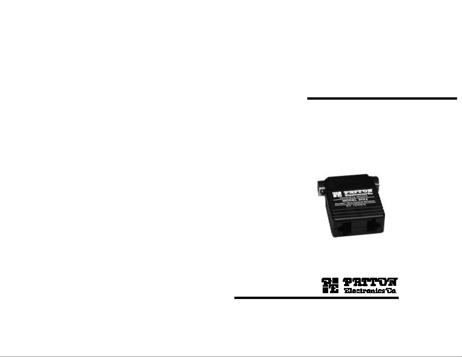
MODEL 3022
MicroStat II
Miniature Statistical
Multiplexer
SALES OFFICE
(301) 975-1000
TECHNICAL SUPPORT
(301) 975-1007
Page 2

TABLE OF CONTENTS
1.0 Warranty Information.................................................................2
1.1 Radio and TV Interference
1.2 Service
2.0 General Information...................................................................3
2.1 Features
2.2 Description
3.0 Installation..................................................................................4
3.1 Connecting the Main Channel
3.2 Connecting the Sub-Channels
3.3 Connecting Two Model 3022s Back-to-Back
3.4 LED Status Indicator
3.5 Power Requirements
3.6 Flow Control Requirements
4.0 Operating Modes........................................................................9
4.1 Local Offline Command Mode
4.2 Online Data Mode
4.3 PassThru Mode
4.4 Local Online Command Mode
4.5 Remote Online Command Mode
5.0 Command Entry.......................................................................11
5.1 Rules for AT Command Entry
5.2 Result Codes
5.3 Complete AT Command Set
6.0 Tutorial ......................................................................................19
7.0 Troubleshooting.......................................................................23
Appendix A - Specifications
Appendix B - Sub-Channel Cables
1.0 WARRANTY INFORMATION
Patton Electronics warrants all Model 3022 components to be
free from defects, and will—at our option—repair or replace the product
should it fail within one year from the first date of shipment.
This warranty is limited to defects in workmanship or materials, and
does not cover customer damage, abuse, or unauthorized modification.
If this product fails or does not perform as warranted, your sole
recourse shall be repair or replacement as described above. Under no
condition shall Patton Electronics be liable for any damages incurred
by the use of this product. These damages include, but are not limited
to, the following: lost profits, lost savings, and incidental or
consequential damages arising from the use of or inability to use this
product. Patton Electronics specifically disclaims all other warranties,
expressed or implied, and the installation or use of this product shall be
deemed an acceptance of these terms by the user.
1.1 RADIO AND TV INTERFERENCE
The Model 3022 generates and uses radio frequency energy, and if
not installed and used properly—that is, in strict accordance with the
manufacturer's instructions—may cause interference to radio and
television reception. The Model 3022 has been tested and found to
comply with the limits for a Class A computing device in accordance
with the specifications in Subpart J of Part 15 of FCC rules, which are
designed to provide reasonable protection from such interference in a
commercial installation. However, there is no guarantee that
interference will not occur in a particular installation. If the Model 3022
does cause interference to radio or television reception, which can be
determined by disconnecting the RS-232 interface, the user is
encouraged to try to correct the interference by one or more of the
following measures: moving the computing equipment away from the
receiver, re-orienting the receiving antenna, and/or plugging the
receiving equipment into a different AC outlet (such that the computing
equipment and receiver are on different branches).
1.2 SERVICE
All warranty and non-warranty repairs must be returned freight
prepaid and insured to Patton Electronics. All returns must have a
Return Materials Authorization number on the outside of the shipping
container. This number may be obtained from Patton Electronics
Technical Service at (301) 975-1007.
Packages received without an
RMA number will not be accepted.
Patton Electronics' technical staff is also available to answer any
questions that might arise concerning the installation or use of your
Model 3022. Technical Service hours: 8AM to 5PM EST, Monday
through Friday.
1
2
Page 3

2.0 GENERAL INFORMATION
Description Direction
1 Protective Ground N/A
2 Transmit Data From Model 3022
3 Receive Data To Model 3022
4 Request to Send From Model 3022
5 Clear to Send To Model 3022
6 Data Set Ready To Model 3022
7 Signal Ground (common return) N/A
8 Carrier Detect To Model 3022
9 9 to 12 Volt Power (optional) To Model 3022
20 Data Terminal Ready From Model 3022
22 Ring Indicator To Model 3022
If your application requires an RS-232 cable between the Model
3022 and the modem, it must be a
straight-through cable
(pinned 1-1,
2-2, 3–3, etc.) of the
shortest
possible length.
3 4
3.0 INSTALLATION
Thank you for purchasing this Patton Electronics product. It has
been designed, manufactured and tested to give you years of troublefree service. If any questions or problems arise during use, please do
not hesitate to call Patton Technical Support at (301) 975-1007.
2.1 FEATURES
• Multiplexes two RS-232 devices into one RS-232 modem link
• Asynchronous sub-channel rates: 110, 300, 1200, 2400, 9600,
19,200 and 38,400 bps
• Asynchronous main channel rates: 1200, 2400, 9600,
19,200 and 38,400 bps and auto detect
• Interface powered–no AC power or batteries required
• Miniature design–plugs directly into DB-25 modem port
• Modular RJ-45 sub-channel ports 1 & 2
• Convenient configuration using extended AT command set
• Configure local and remote units from either local port 1 or 2
• Supports both XON/XOFF and RTS/CTS flow control
2.2 DESCRIPTION
The Patton Model 3022 MicroStatII is a miniature statistical
multiplexer that lets one asynchronous modem communicate with two
asynchronous serial devices
up to 38.4 Kbps, the Model 3022 uses specialized circuitry to monitor
and prioritize data flow. The Model 3022 can be configured so that
upon startup it automatically senses the data rate of the device
connected to either sub-channel. It can also be configured to go into
Data Mode when the modem raises CD. For added convenience, the
Model 3022 allows both local and remote multiplexers to be configured
from local port 1 or 2.
The Model 3022 supports both hardware (RTS/CTS) and software
(X-ON/X-OFF) flow control. Connecting directly to the modem’s DB-25
port, the Model 3022 derives power from the RS-232 interface and
requires no AC power or batteries for operation. Async input devices
connect to the Model 3022 using dual RJ-45 modular interface jacks.
The Model 3022 is housed in a sturdy ABS plastic case measuring
2.66"w x 2.10"l x 0.73"h.
at the same time
. Operating at data rates
The Model 3022 is typically installed by connecting the main
channel to an asynchronous modem and the sub-channels to two
asynchronous serial devices. However, two Model 3022s may also be
connected back-to-back. This section describes connection
procedures, as well as LED indicator function, power requirements,
and flow control requirements.
3.1 CONNECTING THE MAIN CHANNEL
To use both channels of your Model 3022, you must be linked to
another Model 3022, which is usually located remotely and
interconnected with a pair of modems. On one end of the Model 3022,
you will find the asynchronous RS-232 Modem interface. This is a
DB-25 male connector, which plugs directly into the DB-25 female
connector on your modem. The following table lists the pin
connections on the Model 3022's modem interface:
Pin#
Page 4

3.2 CONNECTING THE SUB-CHANNELS
Figure 1. EIA/TIA-561 Interface pinouts for Model 3022 RJ-45 jacks (ports 1 & 2).
1 (DSR) from 3022
2 (CD) from 3022
3 (DTR) to 3022
4 (SG)
5 (RX Data) from 3022
6 (TX Data) to 3022
7 (CTS) from 3022
8 (RTS) to 3022
1
2
3
4
5
6
7
8
PC/AT™ to Model 3022 Pin-Outs:
The two asynchronous, serial sub-channels of the Model 3022 are
RJ-45 female ports that conform to the EIA/TIA-561 interface (see
Figure 1, below). These ports connect to the two serial devices that will
be multiplexed through the main RS-232 port of the Model 3022. Any
combination of RS-232 devices may be connected to the Model 3022's
sub-channels: PCs, terminals, printers, laptops, Macs, plotters, etc.
Every serial device connected to channels 1 and 2 must have a
special interface cable. On one end, this interface cable must have an
RJ-45 male plug; on the other end, it must have a connector that fits
into your RS-232 serial device. The diagrams below and on the
following page show pin connections between the Model 3022's subchannels and common RS-232 serial interfaces. You may use these
diagrams to construct your own cables, or you may purchase pre-made
cables from Patton Electronics. See Appendix B for Patton cable part
numbers.
PC/XT™ or Serial Printer to Model 3022 Pin-Outs:
Serial DB-25 Model 3022 RJ-45
Pin No. Pin No.
6 (DSR) ------------------------------------- 1
8 (CD) --------------------------------------- 2
20 (DTR)------------------------------------ 3
7 (SG) --------------------------------------- 4
3 (RX Data) -------------------------------- 5
2 (TX Data)--------------------------------- 6
5 (CTS)-------------------------------------- 7
4 (RTS)-------------------------------------- 8
Serial DB-9 Model 3022 RJ-45
Pin No. Pin No.
6 (DSR) ------------------------------------- 1
1 (CD) --------------------------------------- 2
4 (DTR) ------------------------------------- 3
5 (SG) --------------------------------------- 4
2 (RCV Data)------------------------------ 5
3 (TX Data)--------------------------------- 6
8 (CTS)-------------------------------------- 7
7 (RTS)-------------------------------------- 8
3.3 CONNECTING TWO MODEL 3022s BACK-TO-BACK
You may connect two Model 3022s back-to-back, bypassing the
modems. To do this, you must have two Patton Model 3P–MF power
supply adapters (see Section 3.5), and one DB-25 female-female RS232 cable. The cable should be no longer than 100 feet (shorter in
some cases), and wired as a "null modem" or "crossover". The
following table shows how to pin a null modem cable that will connect
two Model 3022s back-to-back:
DB-25 Female DB-25 Female
Pin No. Circuit Circuit Pin No.
1 AA -----------------------------------AA 1
2 BA -----------------------------------BB 3
3 BB -----------------------------------BA 2
4 CA -----------------------------------CB 5
5 CB -----------------------------------CA 4
6 CC ----------------------------------CD 20
7 AB -----------------------------------AB 7
9 Pwr ----------------------------------Pwr 9
20 CD ----------------------------------CC 6
Connect the Model 3P-MF adapters to the Model 3022 DB-25
ports. Then connect the null modem cable between the adapters. Do
not plug the adapters into their respective AC outlets until the serial
device connections have been made to the Model 3022s.
(continued)
5 6
Page 5
3.4 LED STATUS INDICATOR
flow
control (flow control between the device and the sub-channel port). In
all
cases, the flow control setting of each Model 3022 port must match
the flow control setting of the device connected to that port.
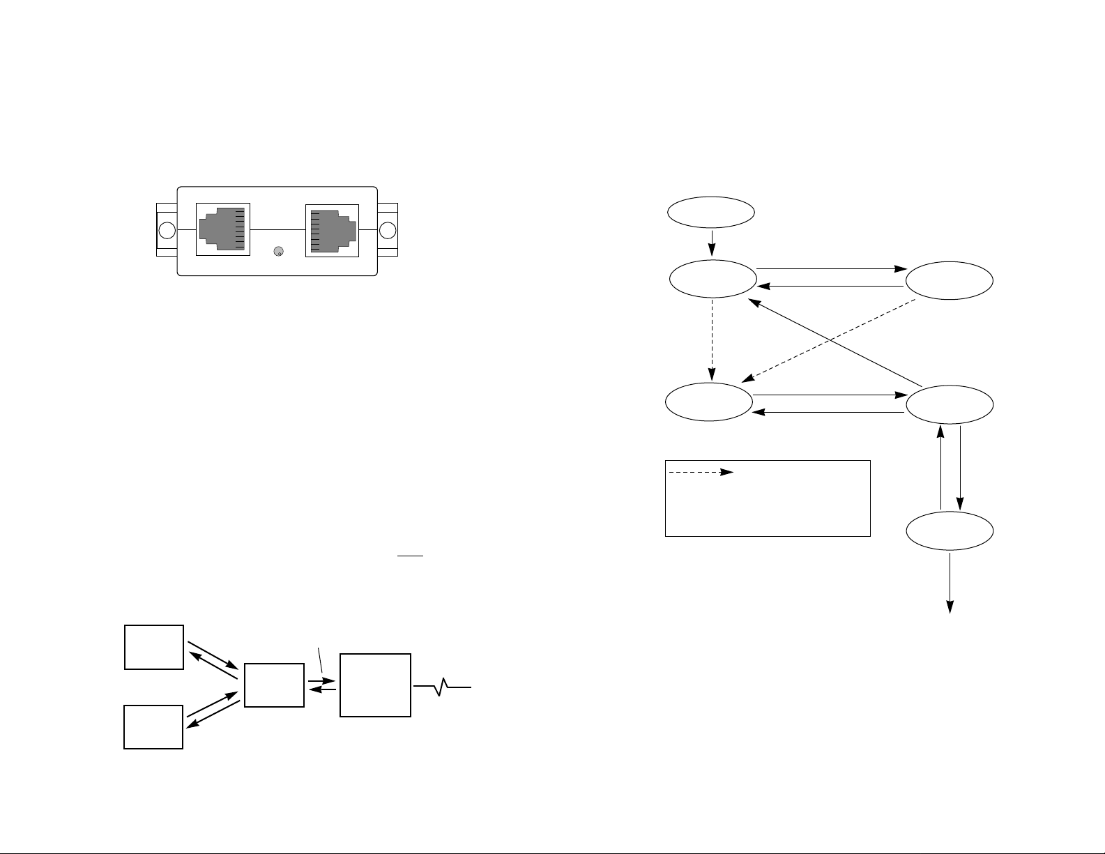
4.0 OPERATING MODES
This section gives descriptions of the five operating modes used by
the Model 3022. When reading these descriptions it may be helpful to
refer to the Navigation Chart shown in Figure 4 (below).
7 8
Figure 2. Model 3022 rear view showing LED indicator
Figure 3. Model 3022 flow control requirements.
Device A
Device B
Model
3022
Modem
Local Flow
Control
Local Flow
Control
Composite Flow
Control
Power Up
Local Offline
Command Mode
Online
Data Mode
Remote Online
Command Mode
Local Online
Command Mode
PassThru
Mode
“\\\”
AT[Y0
(hangup) AT[H
“\\\”
AT[O
AT[D1AT[D0
AT@
(send commands to
remote Model 3022)
Figure 4. Navigation Chart for the Model 3022 Operating Modes
Where you see the above arro w y ou ha ve three
methods of going to Online Data Mode: 1) by letting
the kill timer ( AT[Kn) expire; 2) by the local modem
raising CD (AT[Xn, where n=1); 3) by keying AT[O to
go directly into Online Data Mode.
The Model 3022 has one LED indicator, which is located at the rear
of the unit, between the two modular jacks (see Figure 2, below). This
LED glows to show that the local and remote Model 3022s are in Data
Mode, and are synchronized with each other.
Port 1
3.5 POWER REQUIREMENTS
LED Indicator
Port 2
The Model 3022 derives all necessary operating power from the
DB-25 interface, and requires no AC power or batteries for operation.
When the DCE device is turned on, the Model 3022 automatically
“powers up”. Note: If you do not use a modem (as in Section 3.3), or
your modem is interface powered, you will need to obtain a Patton
Model 3P-MF power supply adapter. This adapter plugs into a standard
AC wall outlet and supplies 100 milliwatts to pins 7 and 9 of the DB-25
interface.
3.6 FLOW CONTROL REQUIREMENTS
For each of the Model 3022 port connections, flow control may be
set for X-ON/X-OFF (software), RTS/CTS (hardware), both methods or
no flow control (see Figure 3, below). For
most
applications, the serial
devices connected to sub-channels 1 and 2 must support local
Page 6

4.1 LOCAL OFFLINE COMMAND MODE
Since the Model 3022 only accepts ASCII characters,
all command lines must start with the attention code "AT" Local
commands follow a [-directive, and are stored in the local command
buffer. Remote commands follow an @-directive, and are stored in the
remote command buffer. The remote commands can only be serviced
when both Model 3022s are synchronized (in Online Data Mode) and
the local Model 3022 is in Online Command Mode (i.e. after /// is
detected). Before a command or string of commands is executed, the
<ENTER> or <CR> must be pressed.
Rule #2. The user may string commands together in one
command line, and separate commands with spaces. However, the
AT[-directive or the AT@-directive may be followed by only
Each command line must end with an <ENTER/CR>.
The Model 3022 will not begin command execution until it receives a
carriage-return character.
Rule #4.
If you made an error while keying a command, you can
edit your entry before you press <ENTER/CR>. Pressing
<BACKSPACE> once deletes the last character entered. Pressing
<BACKSPACE> repeatedly deletes the entire command line, except the
AT command at the beginning of the line. Note: Not all modems
support the backspace edit function.
Rule #5.
Many commands require a numeric parameter. If you
omit this parameter, it will automatically be set at zero.
Rule #6. To store a new configuration in the Model 3022’s non-
volatile memory, the user must key an AT[W or AT@W command.
9 10
When first powered up, the Model 3022 automatically performs a
self-test, configures itself, and enters
this mode, AT[ commands may be entered to configure the local Model
3022. These commands can be entered through sub-channel 1 or 2 on
a “first come, first served” basis.
The Model 3022 will remain in local offline command mode for 2
minutes (or whatever timeout the user has selected). If the user does
not enter a command within this time period, the local Model 3022 will
connect with the remote Model 3022 and automatically enter Online
Data Mode.
4.2 ONLINE DATA MODE
In
Online Data Mode
into one data stream. This single data stream is transmitted through
the modems, and separated back into data channels 1 and 2 at the
remote end. The entire communication process is based upon the
parameters that were set in the command modes.
4.3 PASSTHRU MODE
In
PassThru Mode,
3022 is disabled so that the local modem may be configured or dialed
without disconnecting the Model 3022.
4.4 LOCAL ONLINE COMMAND MODE
In
Local Online Command Mode
to a command while remaining connected to the remote end. This
allows the user to 1) hangup/disconnect the local connection, or 2) go
into Remote Online Command Mode to send commands to the remote
Model 3022.
4.5 REMOTE ONLINE COMMAND MODE
In
Remote Online Command Mode,
entered to configure the remote Model 3022. These commands can be
entered through sub-channel 1 or 2 of the local Model 3022 on a “first
come, first served” basis.
, sub-channels 1 and 2 are merged together
the multiplexing function of the local Model
Local Offline Command Mode
, the local Model 3022 can listen
AT@ commands may be
. In
5.0 COMMAND ENTRY
Before attempting to configure or operate the Model 3022, it is
important to know how the unit handles command entry. This section
provides rules for command entry, describes result codes, and gives a
complete description of each valid AT command.
5.1 RULES FOR "AT” COMMAND ENTRY
Rule #1.
characters and spaces.
Model 3022 aborts execution of the command line and will display an
error reply code. This will occur before you press <ENTER/CR>.
Example:
AT[
30 character Model 3022 command
Rule #3.
If a command line exceeds 30 characters, the
<ENTER/CR>
30
Page 7

5.2 RESULT CODES
Code Word Code Meaning of Code
0 OK Command line executed without errors
4 ERROR Error in the command line
Note1: For screen display purposes, a carriage-return/line feed character sequence
will follow
word
result codes, while only a carriage-return character will follow
numeric
result codes.
Note2: If you do not have a remote Model 3022 connected to the communication
line, an "error" result code will show
before
you hit <ENTER/CR>.
5.3 COMPLETE "AT" COMMAND SET
The Model 3022 command set has two types of commands:
Mode
Setting Commands
, and
Channel Configuration Commands
. The Mode
Setting Commands select operating modes and parameter values for
the Model 3022. The Channel Configuration Commands change the
configuration of the channel that you have selected. Both will have an
immediate effect when you press the <ENTER/CR> key. In order to
store the commands in non-volatile memory, you must key AT[W or
AT@W after the command have been entered.
5.3.1 MODE SETTING COMMANDS
The Mode Setting Commands select operating modes and
parameter values for the Model 3022. The letter “n” that follows the
command letter represents a numeric value. The text describes valid
choices, where (*) is the initial selection after a software reset T
command.
Mode Setting Commands
________________________________________________________
Command Function
________________________________________________________
AT Command line prefix. The attention command precedes all
other commands listed below.
[ Directs the local Model 3022 to execute the following
commands. The Model 3022 discards all characters before
the “[“ character, unless it has a connection to a remote
Model 3022 or you have enabled modem commands.
Mode Setting Commands (continued)
________________________________________________________
Command Function
________________________________________________________
@ Directs the remote Model 3022 to execute the following
commands. The remote Model 3022 responds to all the
commands after the “@” character and returns the result
code. The local unit does not process those commands.
The local Model 3022 rejects the command line if: (a) the
@ command is not immediately following the AT prefix, (b)
the local Model 3022 does not have a connection to the
remote Model 3022, and (c) the remote Model 3022 is in
Local Online Command Mode.
\\\ This command has two functions:
1) If entered while in pass through mode (AT[Y0), local
mux will leave that mode and return to offline command
mode.
2) If received from online data mode, either from subchannel 1 or 2, local mux will enter online command mode
on that particular channel
Cn Selects channel number for subsequent channel
configuration commands. At the start of each command
line, selection reverts to “0 deselects any channel”.
*n = 0, deselects any channel
n = 2, channel 2
n = 1, channel 1
n = 3, communication link (modem)
Dn Tells the remote Model 3022 to enter Remote Online
Command Mode, so that it can be configured. Also tells
the remote Model 3022 to return to Online Data Mode
when configuration is finished. (Note: This command must
be preceded by the AT[ command, and can only be used
when the local Model 3022 is in Local Online Command
Mode).
n = 0, tells the remote Model 3022 to exit Remote
Online Command Mode and return to Online Data
Mode.
11 12
Besides echoing back AT commands, the Model 3022 returns its
own result codes to sub-channel 1 after executing a command. The
result codes indicate whether or not the execution was satisfactory. You
may define result codes as English words (Q0), or numeric digits (Q1),
or you may disable them entirely (Q2). The chart on the following page
describes these codes.
Digit
Page 8

Mode Setting Commands (continued)
________________________________________________________
Command Function
________________________________________________________
Mode Setting Commands (continued)
________________________________________________________
Command Function
________________________________________________________
n = 1, tells the remote Model 3022 to enter Remote
Online Command Mode. The following statements
apply:
• If this command was entered on local sub-channel
1, then it will request sub-channel 1 of the remote
Model 3022 to enter Remote Online Command
mode. Sub-channel 2 will remain in Online Data
Mode.
• After this command is entered, only AT commands
followed by @ will be sent to the remote Model 3022.
H Hangup/disconnect command. Enter when the local Model
3022 is in Local Online Command Mode. Upon receiving
this command, the local Model 3022 will drop DTR at the
composite port for approximately 250 msec, and return to
Local Offline Command Mode.
Jn Selects XON character “n”, where “n” is a single ASCII
character, either a control character or an upper or lower
case alpha character (A through Z, or a through z). NULL,
ETX, STX and Carriage Return characters are not allowed.
Kn Sets the "no activity kill timer" (times out of Local Offline
Command Mode or PassThru Mode and enters Online
Data Mode if no activity is detected) in one quarter minute
increments. Valid values are 0 thru 15. K8 is the default,
resulting an a 2 minute command mode time out. The
timer starts running when the "T" key of the "AT" command
is pressed. Note: this time limit should not be set too
short, or time outs will occur during the entry of AT
commands.
n = 0, disabled
n = 1, 1/4 minute
n = 2, 1/2 minute
n = 3, 3/4 minute
n = 4, 1 minute
n = 5, 75 seconds
n = x, x/4 minute
[Note: if K0 is selected, the local Model 3022 will stay in
Local Offline Command Mode indefinitely, until either CD of
the main channel becomes active (if this option is enabled)
or an AT[0 command is entered.]
Nn Selects XOFF character “n”, where “n” is a single ASCII
character, either a control character or an upper or lower
case alpha character (A through Z, or a through z). NULL,
ETX, STX and Carriage Return characters are not allowed.
O Return to online data mode. If you have enabled
multiplexer operation, the Model 3022 waits for a
connection to the remote Model 3022. You only issue this
to the local Model 3022.
Rn Enables or disables remote control of the Model 3022.
*n = 0, remote control disabled
n = 1, remote control enabled
T Causes a software reset with all Model 3022 modes and
channel configurations set to
Model 3022 will then enter offline command mode.
(Note: The user must wait approximately 5 seconds after
receiving the “OK” response before entering new
commands.)
Un Packet size selection. This configuration is applied to the
composite channel to determine the size (in data bytes) of
the data packet being transmitted to the modem.
n = 0, 8 bytes
*n = 1, 16 bytes
n = 2, 24 bytes
n = 3, 32 bytes
n = 4, 48 bytes
n = 5, 64 bytes
n = 6, 96 bytes
n = 7, 128 bytes
Vn View channel configuration or mode configuration
n = 0, view the configuration of the composite channel
n = 1, view the configuration of sub-channel 1
n = 2, view the configuration of sub-channel 2
n = 3, view the configuration of the composite channel
factory default
values. The
13 14
Page 9

Mode Setting Commands (continued)
________________________________________________________
Command Function
________________________________________________________
W Stores configuration into non-volatile memory
Xn Enables or disables entry into data mode based upon the
status of carrier detect (CD) at the composite port. If
enabled, the Model 3022 will enter data mode when CD is
raised, and exit data mode to go back to offline command
mode when CD goes off. If disabled, the status of CD will
not effect whether or not the Model 3022 enters data
mode.
*n = 0, CD activation of data mode disabled
n = 1, CD activation of data mode enabled
Yn This command has two concurrent functions: 1) Causes
local Model 3022 to enter PassThru Mode. 2) Enables or
disables multiplexer operation. If the AT command to
disable is issued through channel 1, the Model 3022
logically connects channel 1 to the communication link and
disables channel 2. If the AT command to disable is
issued through channel 2, the Model 3022 logically
connects channel 2 to the communication link and disables
channel 1. By disabling the multiplexer operation, you use
the attached modem or serial device for any single channel
purpose without physically disconnecting the Model 3022.
You only issue this to the local Model 3022.
n = 0, disable multiplexer
(Note: This option will not be stored in non-volatile
memory. Multiplexer operation will be enabled again if
AT[Z or \\\ is entered, or upon power up reset
5.3.2 CHANNEL CONFIGURATION COMMANDS
The following commands change the configuration of the channel
that you select with the Cn command. The Cn command must be in the
command line before a channel configuration command, or the Model
3022 rejects the configuration command. The letter “n” that follows the
command letter represents a numeric value. The text describes the
valid choices, where the first choice (*) is the initial selection after a
software reset T or Z command.
____________________________________________________
Command Function
________________________________________________________
Bn Selects baud rate for the selected channel.
*n = 0, auto select (applies only to sub-channels)
see note†
n = 1, 110 bps (applies only to sub-channels)
n = 2, 300 bps (applies only to sub-channels)
n = 3, reserved for future use
n = 4, 1200 bps
n = 5, 2400 bps
n = 6, 4800 bps
n = 7, 9600 bps
n = 8, 19,200 bps
n = 9, 38,400 bps
n = 10, reserved for future use
n = 11, reserved for future use
†
note: sub-channel 1 factory defaults to auto-select;
sub-channel 2 factory defaults to 19.2 Kbps.
En Determines whether the local Model 3022 echoes
the data received in the command mode back to its
sub-channel 1 or 2. (Note: Each sub-channel can have its
own echo option)
*n = 1, echo on
n = 0, echo off
Z Causes a software reset with all Model 3022 modes and
channel configurations set to
previously stored
values.
The Model 3022 will then enter offline command mode.
(Note: The user must wait approximately 5 seconds after
receiving the “OK” response before entering new
commands.)
15 16
Fn Selects the method of flow control used between the
selected Model 3022 port and the peripheral device.
n = 0, none
*n = 1, RTS/CTS
n = 2, XON / XOFF
n = 3, Both methods
Page 10

Channel Configuration Commands (continued)
Power Up
Local Offline
Command Mode
Online
Data Mode
Remote Online
Command Mode
Local Online
Command Mode
PassThru
Mode
“\\\”
AT[Y0
(hangup) AT[H
“\\\”
AT[O
Where you see the above arro w y ou ha ve three
methods of going to Online Data Mode: 1) by letting
the kill timer ( AT[Kn) expire; 2) by the local modem
raising CD (AT[Xn, where n=1); 3) by keying AT[O to
go directly into Online Data Mode.
AT[D1AT[D0
AT@
(send commands to
remote Model 3022)
Figure 5. Operating Overview for the Model 3022
1
2
3
4
5
________________________________________________________
Command Function
________________________________________________________
Gn Allows the user to select the behavior of Carrier Detect on
sub-channels 1 and 2.
*n = 0, CD always ON
n = 1, CD of sub-channel follows composite port CD
Ln Selects data length for the channel.
*n = 1, 8 bit data
n = 0, 7 bit data
Pn Selects parity for the channel.
*n = 0, no parity
n = 1, odd parity
n = 2, even parity
n = 3, mark
n = 4, space
Qn Determines format of result codes sent to sub-channels.
(Note: Each sub-channel can have its own result code
format.)
*n = 0, word codes
n = 2, result codes not sent
n = 1, digit codes
6.0 TUTORIAL
This section provides basic step-by-step instructions for use of the
Model 3022. Using these instructions, plus the AT command
descriptions in Section 5.0, you should be able to operate the Model
3022 in almost any application. If you have additional questions, do not
hesitate to contact Patton Technical Support at (301)975-1007.
When going through the step-by step instructions, use Figure 5
(below) as a guide to “walk” from mode to mode. This Tutorial assumes
a typical installation, where two Model 3022s are connected to each
other via modem link, and each Model 3022 sub-channel port is
connected to a PC or similar serial RS-232 device.
Sn Selects the number of stop bits for the channel.
*n = 1, 1 stop bit
n = 0, 2 stop bits
17 18
Page 11

Step #1 - Verifying Local Setup Parameters
Step #2 - Dialing the Local Modem (continued)
The first step in using the Model 3022 is checking to see that the
local Model 3022 is connected and configured properly. Follow
these instructions:
1) Power up the local modem. This should power up the local
Model 3022 and put the unit automatically in Local Offline
Command Mode. You will now have 2 minutes to key in the next
command before the Model 3022 times out and goes into Online
Data Mode. (If you do time out and go to Online Data Mode, you
will not be able to enter any commands. Simply Key \\\, then AT[H
to return to Local Offline Command Mode.)
2) Key AT[ from the terminal connected to port 1 or port 2. The
unit responds “OK” to let you know you are in a command mode.
3) Key AT[V3 to view the setup parameters of the local Model 3022
DB-25 port. Check to see that these parameters match those of
your local modem. If not, change the necessary parameters using
the AT[ commands listed in Section 5.0.
4) Key AT[V1 and repeat the above process for sub-channel 1.
5) Key AT[V2 and repeat the above process for sub-channel 2.
6) If all three sets of parameters match those of your system, move
to step #2.
3) Go to Online Data Mode. There are three ways you can do this:
The first way is to wait for the “no activity kill timer” to expire, after
which you will go automatically into Online Data Mode. In the
default setting, this should take about 20-30 seconds after you
have dialed the modem. Second, you can key AT[O to go directly
from PassThru Mode to Online Data Mode. Third, if you have set
the AT[Xn parameter to n=1 and the AT[Kn parameter to n=0, the
Model 3022 will go into Online Data Mode as soon as it sees CD
on the modem.
Step #3 - Verifying the Remote Setup Parameters
If you have performed steps 1 and 2 correctly, the Local Model
3022 should be in Online Data Mode, and you should have an active
connection between the local and remote modems. Check to see that
the activity LED on your local Model 3022 is ON. If not, consult Section
7.0 Troubleshooting.
Assuming that you have a good connection and are in Online Data
Mode, the next step is to verify the setup parameters of the remote
Model 3022. Follow these instructions:
1) Key \\\ to go to Local Online Command Mode. This will keep
your modem connection active, but will allow you to enter
commands as well (remember, you cannot enter commands in
Online Data Mode).
Step #2 - Dialing the Local Modem
After confirming the proper configuration of the local Model 3022,
the next step is to dial the local modem so you can make a connection
to the remote modem and Model 3022. Follow these instructions:
1) Key AT[Y0 to go from Local Offline Command Mode to
PassThru Mode. The unit responds “OK”. You are now connected
directly to your local modem, with the multiplexing function of the
local Model 3022 disabled. It is as if your terminal has a straight
through connection to the modem.
2) Dial the local modem as you normally would if directly
connected. (example: ATDT13019751000). After handshaking
procedures, the unit responds “Connect 9600”.
(continued)
19 20
2) Key AT[D1 to go to Remote Online Command Mode. This will
let you send commands to the
you are in Remote Online Command Mode, key AT@. The unit
should respond “OK”.
3) Key AT@V3 to view the setup parameters of the remote Model
3022 DB-25 port. Check to see that these parameters match
those of your local modem. If not, change the necessary
parameters using the AT@ commands listed in Section 5.0.
4) Key AT@V1 and repeat the above process for sub-channel 1.
5) Key AT@V2 and repeat the above process for sub-channel 2.
6) If all three sets of parameters match those of your system, move
to step #4.
remote
(continued)
Model 3022. To verify that
Page 12

Step #4 - Enabling End-to-End Data Transmission
7.0 TROUBLESHOOTING
SYMPTOM POSSIBLE PROBLEM SOLUTION
1. ERROR
response to AT[Y0
command
2. ERROR
response to AT[H
command
3. Model 3022
does not respond to
\\\ command
4. Keying
garbage/incorrect
characters
5. No responses to
keying appears on
screen; 3022
appears to be
'locked up'.
Model 3022 is in
PassThru Mode
Model 3022 is in Local
Online Command
Mode
Model 3022 is in Local
Offline Command
Mode
Model 3022 is in PassThru Mode
Model 3022 is already
in Local Online
Command Mode
Model 3022 is already
in Local Offline
Command Mode
Bit rate mismatch on
connected
channel
3022 has timed out
and is waiting to go
into Online Data Mode
Kill Time Out (Kn) may
be too short
Enter \\\ to return to
Local Offline
Command Mode
Key AT[H to enter
Local Offline
Command Mode, then
re-enter AT[Y0
Model 3022 is already
in default Mode. Reinitiate start-up
sequence.
Model 3022 does not
need disconnection
Issue AT[O to resume
Online Data Mode and
proceed with data
transfer. Then issue \\\
and AT[H to hang up.
Model 3022 is already
in default mode.
Change bit rate of
connected device and
key characters until
characters keyed are
the same as on-screen
characters.
Key \\\ to re-enter Local
Online Command
Mode. Then key AT[H
to re-enter Local
Offline Command
Mode.
Lengthen Kill Time Out
(Kn command)
If you have performed steps 1 thru 3 correctly, all four serial
devices (two at the local end and two at the remote end) should be set
up to communicate with each other as if they were connected back to
back. (Note: be certain that the remote devices are turned on and that
all physical connections are made properly.) To enable end-to-end data
transmission, follow these instructions:
1) Key AT[D0 to go from Remote Online Command Mode to Local
Online Command Mode. The unit responds “OK”.
2) Key AT[O to go from Local Online Command Mode to Online
Data Mode. The unit will not issue a response because it is no
longer in a command mode.
Step #5 - Ending the Connection
If you have performed steps 1 thru 4 successfully, your four serial
devices should be able to communicate across the modem link. If this
is not happening, consult Section 7.0 Troubleshooting. The only
remaining step is to end the connection. Follow these instructions:
1) Key \\\ to go from Online Data Mode to Local Online Command
Mode. The unit responds “OK”.
2) Key AT[H to hangup/disconnect the modem link and return to
Local Offline Command Mode. The unit responds “OK”.
3) When the local modem is powered down, the Model 3022 will
power down as well. Any configuration changes you have entered
will be stored in the Model 3022’s non-volatile memory if they have
been saved with the AT[W or AT@W command.
21 22
Page 13

6. ERROR
response to AT[
command
7. Unit appears to
be locked-up
Unit is in PassThru
Mode
Flow control
parameters set
incorrectly
Improper sub-channel
cable pinout
Model 3022 not
plugged into an RS232 port, or is plugged
into a DB-25 port that
cannot supply
sufficient operating
power (short haul
modem, laptop, etc.)
(continued)
Key \\\ to re-enter Local
Offline Command
Mode
Disconnect Model
3022, then set
Terminal Device Flow
Control (RTS/CTS or
XON/XOFF).
Reconnect Model
3022, then set Model
3022 flow control (Fn
Command) to be the
same Flow Control
Method as Terminal
Device.
Re-wire cable
according to pinout
diagrams in Section
3.2.
It needs power! Plug it
into an RS-232 port or
obtain Model 3P-MF
power supply adapter.
SYMPTOM POSSIBLE PROBLEM SOLUTION
8. Modem
connection has
been established,
but 3022 will not
pass data
Model 3022 is still in
PassThru Mode
Improper bit rate at
modem channel (C3)
Flow control
parameters set
incorrectly
Data format (data bits,
parity, stop bits) set
incorrectly
(continued)
Reset Kill Time Out
(Kn command) to be
shorter time period.
Reset 3022 to enter
Online Data Mode
based upon status of
CD (AT[X1 command)
Break the modem
connection and check
the channel 3
configurations on both
local and remote
Model 3022s (AT[V).
Then reset C3 for
proper throughput rate
(AT[C3Bn).
Verify proper flow
control on all three
channels of local and
remote 3022
Verify correct data
format on all three
channels of local and
remote 3022
SYMPTOM POSSIBLE PROBLEM SOLUTION
23 24
Page 14

9. ERROR
response to remote
configure AT@
command
10. Modem will not
respond to AT
commands
Remote Model 3022
has not been alerted to
respond to remote
commands
Remote Model 3022
has been disabled for
remote configuration
Remote Model 3022 is
not in Online Data
Mode
Model 3022 is not in
PassThru Mode
Modem is not in
command mode
Issue AT[D1 command
to local Model 3022
(this command will be
passed thru to remote
3022 and will cause it
to respond to remote
commands)
Issue AT[R1 command
to both local and
remote 3022 (avoid
changing the default
R1 setting so that the
unit may always be
configured remotely if
necessary)
Wait until remote 3022
times out or issue AT[O
to remote 3022.
Issue AT[Y0 to Model
3022
Consult modem
manual
SYMPTOM POSSIBLE PROBLEM SOLUTION
APPENDIX A
SPECIFICATIONS
Sub-Channels (Serial Devices)
Interface: RJ-45, V.24/RS-232-C
Configuration: DCE
Transmission: Asynchronous, full duplex
Baud Rate: 110, 300, 1200, 2400, 4800, 9600, 19200,
38400 bps, selectable or auto detected
Word Size: 7 or 8 data bits
Parity: Odd, even, mark, space, or none
Stop Bits: 1 or 2
Flow Control: Hardware (RTS/CTS), software (XON/XOFF)
Main Channel (Modem)
Interface: DB-25 male, DTE, V.24/RS-232-C
Transmission: Asynchronous, full duplex
Baud Rate: 1200, 2400, 4800, 9600, 19200, 38400 bps
selectable
Flow Control: RTS/CTS or no flow control
Environmental
Temp Range: 0 - 70ºC (32 - 158ºF)
Altitude: 0 - 15,000 Feet
Humidity: up to 95% (non-condensing)
Dimensions: 2.7” x 2.1” x 7.4” (69mm x 53mm x 19mm)
Weight: 0.10 lb (0.045 Kg)
25 26
Page 15

APPENDIX B
atton Part Number Cable Description (application)
3022-25M....................DB-25 Male, to RJ-45 Male, 6 ft.
(adapts to Serial Printer)
3022-25F ....................DB-25 Female, to RJ-45 Male, 6 ft.
(adapts to PC/XT
TM
serial port)
3022-9F ......................DB-9 Female, to RJ-45 Male, 6 ft.
(adapts to PC/AT
TM
serial port)
3022-45M....................RJ-45 Male, to RJ-45 Male, 6 ft.
(adapts to EIA/TIA-561 interface)
27
SUB-CHANNEL CABLES
No sub-channel cables are supplied with the Model 3022. You may
construct your own cables using the pin-out diagrams in Section 5.2, or
you may purchase one of the pre-made adapter cables listed below.
Custom lengths are available.
Note: The part numbers below are completely distinct from the
model number/suffix combinations shown on the previous page.
not combine these part numbers with the model number of the
standalone unit when ordering. These are separate items.
P
Do
 Loading...