

Page 1

B
MODEM SHARING DEVICE
Doc #: 137001UA
Part #: 07M3012-A
3012/V24 (CTS MSD-2C)
3014/V24 (CTS MSD-4C)
3018/V24 (CTS MSD-8C)
INSTALLATION AND OPERATIONS MANUAL
January 3, 2000
An ISO-9001
Certified Company
Copyright© 2000 Patton Electronics Co., All Rights Reserved
Page 2

B
MODEM SHARING DEVICE
Doc #: 137001UA
Part #: 07M3012-A
3012/V24 (CTS MSD-2C)
3014/V24 (CTS MSD-4C)
3018/V24 (CTS MSD-8C)
INSTALLATION AND OPERATIONS MANUAL
An ISO-9001
Certified Company
Copyright© 2000 Patton Electronics Co., All Rights Reserved
Page 3

PATTON ELECTRONICS CO.INSTALLATION AND OPERATIONS MANUAL
3012-14-18/V24
137001UA
COPYRIGHT NOTICE
Copyright© 2000 Patton Electronics Co., All Rights Reserved.
PROPRIETARY NOTICE
The information contained herein is proprietary and confidential to Patton Electronics
Co. Any reproduction or redistribution of this publication, in whole or in part, is
expressly prohibited unless written authorization is given by Patton Electronics Co.
WARRANTY NOTICE
WARRANTIES: Patton Electronics Co. (hereafter referred to as Patton) warrants
that its equipment is free from any defects in materials and workmanship. The
warranty period shall be two years from the date of shipment of equipment. Patton’s
sole obligation under its warranty is limited to the repair or replacement of the
defective equipment, provided it is returned to Patton, transportation prepaid, within
a reasonable period. This warranty will not extend to equipment subjected to
accident, misuse, alterations or repair not made by Patton or authorized by Patton in
writing.
PUBLICATION NOTICE
This manual has been compiled and checked for accuracy. The information in this
manual does not constitute a warranty of performance. Patton reserves the right to
revise this publication and make changes from time to time in the content thereof.
Patton assumes no liability for losses incurred as a result of out-of-date or incorrect
information contained in this manual.
i
Page 4

PATTON ELECTRONICS CO.INSTALLATION AND OPERATIONS MANUAL
3012-14-18/V24
137001UA
Table of Contents
CHAPTER 1 - OPERATON
Channel Selection Modes (4 and 8 port only) .................................................. 1-2
Anti-Streaming ............................................................................................ 1-2
Front Panel Indicators and Switches .............................................................. 1- 3
CHAPTER 2 - SETUP AND INSTALLATION
Power Connection .......................................................................................2-1
Factory Configuration Switch Settings ............................................................. 2- 1
Disassembly ............................................................................................... 2-2
Installation .................................................................................................. 2-3
Equipment Grounding (Switch Pos 6) .............................................................. 2-3
Anti-Streaming (Switch Pos 1,2,3,4) .............................................................. 2 -3
Switching Mode Selection (Switch Pos 5) MSD-4C & MSD-8C Only ..................... 2-4
CTS Delay on the MDS-2C (Switch Pos 5) ....................................................... 2-4
CTS Delay on the MSD-4C & MSD-8C (JP6).................................................... 2-4
Unregulated Power to Pins 9 & 10................................................................2- 4
Factory Test Jumpers (JP1,JP2,JP3) ............................................................ 2-4
APPENDIX
TECHNICAL SPECIFICATIONS......................................................................... A-1
Typical Application ....................................................................................... A-2
RS-232 Pin Out .......................................................................................... A-2
Strapping Guides ......................................................................................... A-3
iii
Page 5
PATTON ELECTRONICS CO.INSTALLATION AND OPERATIONS MANUAL
3012-14-18/V24
137001UA
CHAPTER 1 - OPERATON
The Patton MSDs are network enhancement accessories intended for DCE sharing
applications. The Patton MSDs allows up to eight terminals or DTE devices to share
a single point to point or multi-drop polled communication link.
The Patton MSDs allow for immediate expansion of a system without the
requirement of additional Modems or communication lines. All MSDs are protocol
transparent and operate in synchronous or asynchronous environments at rates up
to 38.4Kbps. Clocking is provided by the attached DCE device on the Master Port.
The Patton MSDs have Anti-Streaming capabilities that include selectable time-outs
depending on your system transmission speed, and a setting to disable antistreaming for large data block transfers. No special cables or adapters are required
for normal DTE-DCE operation. All interconnects are made via industry standard
female DB-25 connectors located on the rear panel of the units. A linear 110/
220V, UL, CSA and TÜV approved power supply is internal to the unit.
PW SD RD 1 2 3 4 1 2 3 4
PW SD RD 1
ACTIVE STREAM
PW SDRD 1212
ACTIVE STREAM
ACTIVE
2 3 4 5 6 7 8
SUB-CHANN EL STATU S
SUB-CHANNEL STATUS
STREAM
1
2 3 4 5 6 7 8
ENABLE/DISABLE
12
ENABLE/DISABLE
123
SUB-CHANNEL STATUS
1234567
1-1
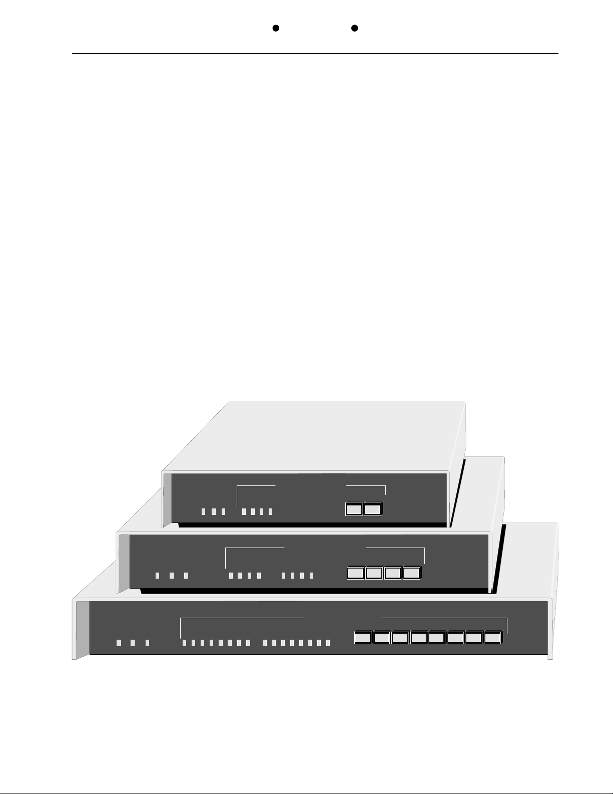
INTERNATIONAL
SERIES
MSD-2C
MSD-4C
4
ENABLE/DISABLE
MSD-8C
8
Operation
Page 6

PATTON ELECTRONICS CO.INSTALLATION AND OPERATIONS MANUAL
137001UA
3012-14-18/V24
Channel Selection Modes (4 and 8 port only)
The Patton MSD provides two selectable sub-channel service modes of operation:
Scanning Mode and Priority Mode. Depending on system requirements, either mode
may be selected by internal DIP switch settings. Both modes switch on activity from
the sub-channel. Activity is defined as raising RTS on a sub-channel.
In the Scanning Mode the Patton MSD scans each sub-channel in sequence,
beginning with channel 1. This rotational sequence is repeated continually with each
attached sub-channel having equal access to the communications link. When RTS
from a sub-channel becomes active, that sub-channel is given a CTS signal and
switched through to the master port by the MSD. All remaining sub-channels are
locked out until the first device becomes inactive. When the sub-channel device
becomes inactive, the MSD will resume scanning the sub-channels for another active
signal.
When configured for Priority Mode operation, the Patton MSD monitors all subchannels simultaneously with sub-channel 1 having the highest priority. When a subchannel becomes inactive, the MSD will automatically default to the highest priority
(lowest number) sub-channel with activity.
Port Enable/Disable front panel switches must be pushed in (GREEN indication) for
a sub-channel to access the main channel, regardless of the mode of operation
selected.
Anti-Streaming
A typical problem often encountered in DDS and leased-line, polled environments is a
“Streaming” remote terminal. The streaming problem can tie up an entire circuit until
the offending terminal has recovered or is powered down. A streaming condition
occurs when a sub-channel remains active, disrupting the polling sequence. The MSD
provides two user selectable modes of controlling a streaming condition: an
automatic Anti-Streaming Abort Timer, and a manual Operator Control mode (front
panel push button switch).
The streaming condition caused by one of the attached terminals can be quickly
bypassed by the Patton MSD via the associated front panel locking switches. A
switch is provided for each sub-channel and permits the rapid removal of a
streaming terminal without having to disconnect any cables or power down the
offending terminal. Terminals may be selectively removed for self-test and
maintenance without affecting the remaining sub-channels. Once the streaming
condition has been corrected, the front panel switch is simply depressed to the
locked (Enable) position (Green indicator ON) to re-establish normal operation.
Operation
1-2
Page 7

PATTON ELECTRONICS CO.INSTALLATION AND OPERATIONS MANUAL
3012-14-18/V24
137001UA
Front Panel Indicators and Switches
The front panel LED indicators associated with each sub-channel identify the active
port. A green POWER ON LED indicates when AC voltage is applied. Two adjacent
green LED indicators illuminate in union with individual port activity and identify
Transmit Data (TXD) and Receive Data (RXD) activity.
Positive latching type switches are provided for each DTE port. These switches allow
you to isolate or remove a streaming terminal. The switch is GREEN when the
channel is active. To disable a sub-channel, push in the switch and it will click to the
out position, and turn BLACK.
1-3
Operation
Page 8
PATTON ELECTRONICS CO.
3012-14-18/V24
INSTALLATION AND OPERATIONS MANUAL
137001UA
Caution, Disconnect the POWER Before Removing The Cover.
Vorsicht, Befor Deckung Abnehmen Mach Strom Zu.
CHAPTER 2 - SETUP AND INSTALLATION
Power Connection
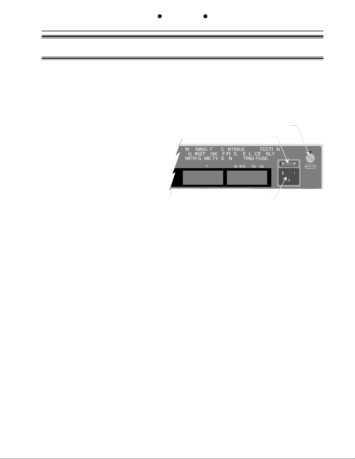
Before connecting the MSD to an AC power source the top cover must be installed
and secured with the supplied screws. The unit is supplied with a 110/220V voltage
switch. Turn the switch with a coin or
screw driver to the appropriate voltage
for your country. EXAMPLE: United
States of America, set to 110V. The
unit is supplied with an IEC power
connector next to the voltage select
switch. Plug the power cord into the
connector until it is firmly seated. You
may now connect the power cord
into your AC outlet.
IEC Power Connector
110 / 220VA Switch
Fuse Drawer
110
220
Factory Configuration Switch Settings
The MSDs are configured prior to shipment with the switches set to the following
default positions:
3012/V24 (CTS MSD-2C)
Switch 3 - positions 4, 5 and 6 to
OFF,OFF,
OFF, 1, 2 and 3 to
OFF,OFF,
Anti-Stream = 40sec. and Disabled
CTS Delay = No Delay
Signal Ground not connected to Chassis Ground
JP4 and JP5 to
ININ
IN
ININ
Provide Pin 9 and 10 Test Voltage
JP1, JP2, and JP3 to
ININ
IN
ININ
Factory Testing Straps Must be installed
ONON
ON
ONON
3014/V24 (CTS MSD-4C)
Switch 5 - positions 4 and 6 to
OFFOFF
OFF, 1, 2, 3 and 5 to
OFFOFF
Anti-Stream = 40sec. and Disabled
Switching Mode = Priority
Signal Ground not connected to Chassis Ground
2-1
ONON
ON
ONON
Setup & Installation
Page 9

137001UA
3012-14-18/V24
INSTALLATION AND OPERATIONS MANUALPATTON ELECTRONICS CO.
JP4 and JP5 to
ININ
IN
ININ
Provided Pin 9 and 10 Test Voltage
JP6 to
OUTOUT
OUT
OUTOUT
CTS delay = No Delay
JP1, JP2 and JP3 to
ININ
IN
ININ
Factory Test Jumpers must be installed
3018/V24 (CTS MSD-8C)
Switch 9 - positions 4 and 6 to
Anti-Stream = 40sec. and Disabled
Switching Mode = Priority
Signal Ground not connected to Chassis Ground
JP4 and JP5 to
ININ
IN
ININ
Provided Pin 9 and 10 Test Voltage
JP6 to
OUTOUT
OUT
OUTOUT
CTS delay = No Delay
OFFOFF
OFF, 1, 2, 3 and 5 to
OFFOFF
ONON
ON
ONON
JP1, JP2 and JP3 to
ININ
IN
ININ
Factory Test Jumpers must be installed
If the system application requires one or more of the default settings to be changed,
it will be necessary to remove the top cover of the enclosure to access and change
the DIP switches located on the printed circuit board.
Disassembly
Remove the top cover by unscrewing the phillips head screws located on the left and
right sides of the unit. The configuration switches and jumpers are located on the
PCB as indicated on the appropriate strapping guide in the Appendix of this manual.
After the switch selection activity is completed,
C
ONNECTING TO AN
AC P
OWER SOURCE
.
R
EINSTALL THE TOP COVER
BEFORE
Setup & Installation
2-2
Page 10
PATTON ELECTRONICS CO.
3012-14-18/V24
INSTALLATION AND OPERATIONS MANUAL
137001UA
Installation
Select an appropriate location accessible to and within six feet of an AC power
outlet. The outlet must have a ground pin receptacle for product warranty. The DCEto-DTE cabling between each attached device and the MSD should be “Straight
Through”, shielded and terminated with male DB-25 connectors. Sub-Channels are
marked “PORT 1” through “PORT 8”; the Master Port is marked “MASTER”. If any
terminal has a priority service mode, ensure it is connected to the port connector
designated “PORT 1” on the rear panel of the MSD. Secure other terminals to be
serviced to the remaining PORT connectors. Connect the MODEM to the connector
designated “MASTER”.
Equipment Grounding (Switch Pos 6)
Position 6 on the DIP switch provides for grounding interconnection in those systems
requiring a connection between (Frame Ground) and (Signal Ground). Connect ONLY
if required.
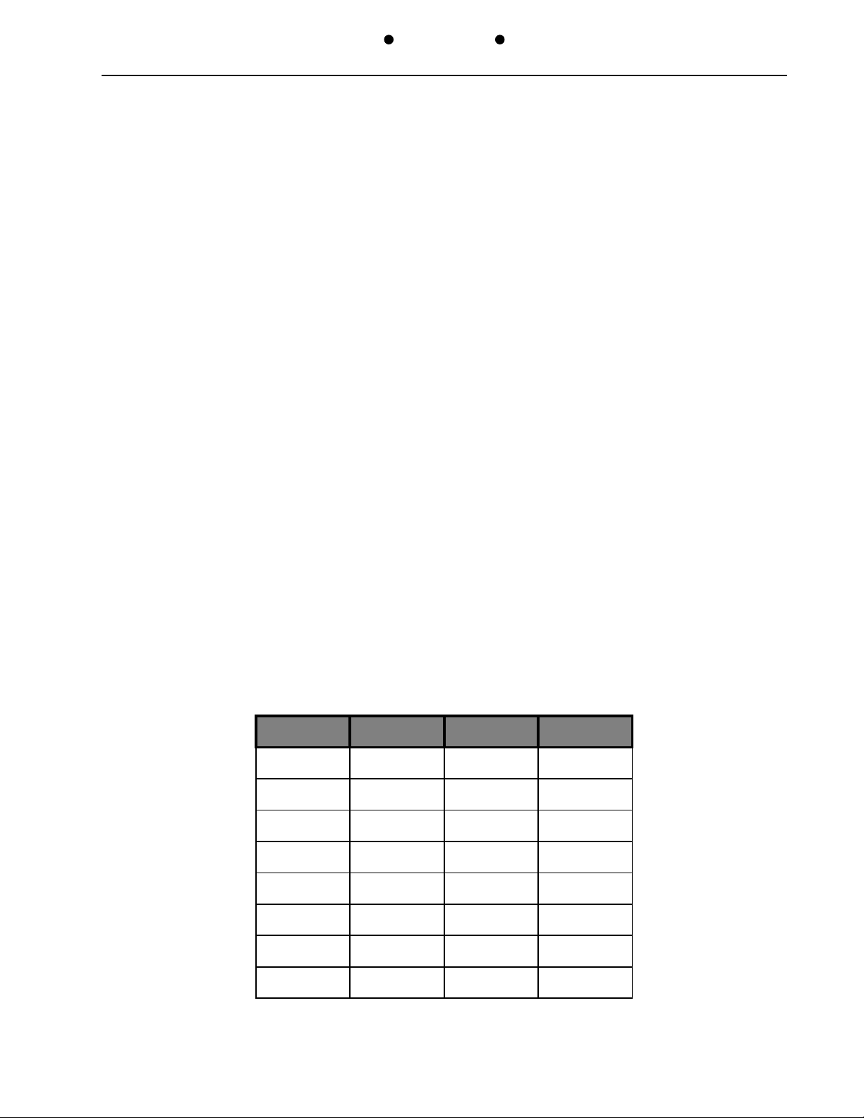
Anti-Streaming (Switch Pos 1,2,3,4)
The maximum data block size is user selectable via the internal DIP switch positions
1, 2, and 3. As shown below eight block sizes are provided to the user. To disable
anti-streaming set position 4 to
OFFOFF
OFF. The maximum block size is normally defined at
OFFOFF
the time of installation. The MSD will isolate the affected sub-channel until the
streaming condition has been corrected, then automatically re-establish
communications as before.
3 2 1 Time
OFF OFF OFF .02 sec
OFF OFF ON .04 sec
OFF ON OFF .08 sec
OFF ON ON .30 sec
ON OFF OFF 1.3 sec
ON OFF ON 5.0 sec
ON ON OFF 20.0 sec
ON ON ON 40.0 sec
2-3
Setup & Installation
Page 11

137001UA
3012-14-18/V24
INSTALLATION AND OPERATIONS MANUALPATTON ELECTRONICS CO.
Switching Mode Selection (Switch Pos 5)
3014/V24 (CTS MSD-4C) & 3018/
V24 (CTS MSD-8C) Only
To select Priority Mode, set switch position 5 to
switch position 5 to
OFFOFF
OFF. The Modem connected to the master port of the MSD
OFFOFF
ONON
ON. To select Scanning Mode, set
ONON
must toggle CTS in response to RTS for the MSD to operate correctly. In addition,
the terminals connected to the ports must toggle RTS to gain control of the unit. If
the terminal will not toggle RTS, it will not work with an MSD.
CTS Delay on the 3012/V24 (CTS MDS-2C) (Switch Pos 5)
If a 25 mS CTS delay is desired, set switch position 5 to
set switch position 5 to
OFFOFF
OFF.
OFFOFF
ONON
ON. If no delay is required
ONON
CTS Delay on the 3014/V24 (CTS MSD-4C) & 3018/V24 (CTS MSD-8C) (JP6)
If a 25 mS CTS delay is desired, install the CTS Delay Jumper.
Unregulated Power to Pins 9 & 10
Jumpers JP4 and JP5 must be installed to provide unregulated power on pins 9 &
10 on the port DB-25 connectors.
Factory Test Jumpers (JP1,JP2,JP3)
The three test jumpers JP1, 2 and 3, must be installed for the unit to properly
function. These jumpers are used in the manufacture and test of the product prior
to shipment.
Setup & Installation
2-4
Page 12

PATTON ELECTRONICS CO.INSTALLATION AND OPERATIONS MANUAL
3012-14-18/V24
APPENDIX
TECHNICAL SPECIFICATIONS
137001UA
Applications
Multiple Sync/Async devices operating in a polled
environment, sharing one RS-232 DCE interface
Capacity
One to Eight RS-232 Synch/Async Terminals;
Standard DB-25 V.24 (female) connectors for each
channel
Data Format
Data transparent at all data rates
Data Rates
Up to 38.4Kbps
Timing
External:.... From Modem or TX Clock provided on
Channel 1 (pin 24)
Anti-streaming
Automatic: Selectable timeout intervals or disable
Terminal Service Modes (4 & 8 Port Only)
Scanning Mode:..... Channels are continuously
scanned for “RTS” on a
sequential basis.
Priority Mode: ....... Channels are simultaneously
monitored for “RTS” channel
one has highest access.
Sub-Channel Interface
Modem Interface
EIA RS-232, V.24 female connector (DB-25)
Front Panel
Indicators: ... Power, Send/Receive Data, Channel
Active, Channel Stream
Switches: .... Enable/Disable each Sub-Channel
Power Source
100-120/200-240VAC, 50 to 60Hz,
0.16/0.08A, Switch Selectable
Environmental
Operating Temp: ..... 32° to 122°F (0° to 50°C)
Relative Humidity: ... 5 to 90% non-condensing
Altitude: ................ 0 to 10,000 feet
Dimensions
(MSD-2C)
Height: ......... 1.75 inches (4.44 cm)
Width: ......... 8.90 inches (22.60 cm)
Length: ......... 10.00 inches (25.40 cm)
(MSD-4C)
Height: ......... 2.05 inches (5.21 cm)
Width: ......... 13.35 inches (33.09 cm)
Length: ......... 9.00 inches (22.86 cm)
(MSD-8C)
Height: ......... 1.75 inches (4.44 cm)
Width: ......... 17.00 inches (43.18 cm)
Length: ......... 11.00 inches (18.93 cm)
Weight
EIA RS-232, V.24 female connectors (DB-25)
2.2 lbs (1.0 Kg) 3012/V24 (CTS MSD-2C)
4.5 lbs (2.1 Kg) 3014/V24 (CTS MSD-4C)
4.5 lbs (2.1 Kg) 3018/V24 (CTS MSD-8C)
A-1
Appendix
Page 13
137001UA
g
g
g
g
PATTON ELECTRONICS CO.INSTALLATION AND OPERATIONS MANUAL
3012-14-18/V24
Leased
or
Dial Line
V.24 MODEM
V.24
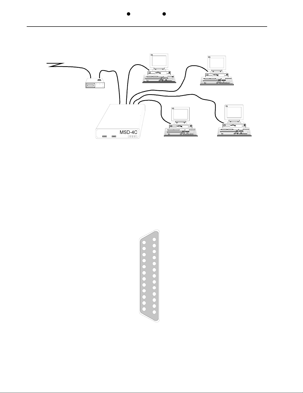
Typical Application
V.24
V.24
V.24
T ransm it Clock (fro m D C E )
Receive Clock (from DCE)
Da ta Termina l Re ad y (fr om DTE)
Indic ato r ( fr om DCE)
Rin
Ex te r nal T ra n s mit C lo c k (from DT E)
Appendix
14
15
16
17
18
19
20
21
22
23
24
25
1
2
3
4
5
6
7
8
9
10
11
12
13
RS-232 Pin Out
A-2
Sh ield (comm o n)
Transm it Data (from DTE)
Receive Data (from DCE)
Request to Send (from DTE)
Clear To Se n d (from D C E )
Data Set R e ady (fro m D C E )
n al G rou nd (comm on)
Si
Data Carrier De tect (from DC E )
P ositive Tes t Volta
Ne
ative Test Vo ltage (from DC E )
e (from DC E )
Page 14
PATTON ELECTRONICS CO.INSTALLATION AND OPERATIONS MANUAL
g
g
g
g
g
g
3012-14-18/V24
SW3
123456
Anti-Str eam Timer
Anti-Stream Enable=ON/ Disable=OFF
CTS Delay 25mS=ON/No Delay=OFF
Signal to Chassis Ground
ONOFF
JP1+5V
137001UA
Ne
Volta
Positive
Volta
Positive
Test
Volta
Ne
ative
Test
Volta
+8V
-8V
ative
Test
Test
e
e
-8V
+8V
JP2
JP3
JP4
e
JP5
e
JP5
JP4
3012/V24
(CTS MSD-2C)
CTS Delay
25mS Insta l led
No Delay Removed
JP6
SW5
123456
JP3
JP2
ONOFF
Anti-Str eam Timer
Anti-Stream Enable=ON/ Disable=OFF
Priority Mode=ON/Sc an Mode=OFF
Signal to Chassis Ground
+5V
JP1
3014/V24
(CT S MSD-4 C)
A-3
Appendix
Page 15

137001UA
g
g
g
Ne
Volta
PATTON ELECTRONICS CO.INSTALLATION AND OPERATIONS MANUAL
JP5
ative
Test
JP4
Positive
Test
e
Volta
25mS Insta l led
No Delay Removed
3012-14-18/V24
e
CTS Delay
JP6
SW9
-8V
+8V
+5V
JP3
JP2
JP1
123456
Anti-Str eam Timer
Anti-Stream Enable=ON/Disable=OFF
Priority Mode=ON/Scan Mode=OFF
Signal to Chassis Ground
ONOFF
3018/V24
MSD-8 C
Appendix
A-4
Page 16

B
7622 Rickenbacker Drive
Gaithersburg, MD 20879
Sales: 301 975-1000 Support: 301 975-1007
Web Address: www.patton.com
 Loading...