

Page 1

Access Server
Administrator’s Reference Guide
Sales Office: +1 (301) 975-1000
Technical Support: +1 (301) 975-1007
E-mail: support@patton.com
WWW: www.patton.com
Document Number: 107001U Rev. B
Part Number: O7MDAS-ARG-B
Revised: March 12, 2001
Page 2

Patton Electronics Company, Inc.
7622 Rickenbacker Drive
Gaithersburg, MD 20879 USA
Voice: +1 (301) 975-1000
Fax: +1 (301) 869-9293
Technical Support: +1 (301) 975-1007
Technical Support e-mail: support@patton.com
WWW: www.patton.com
Copyright © 2000, 2001, Patton Electronics Company. All rights reserved.
The information in this document is subject to change without notice. Patton Electronics assumes no liability
for errors that may appear in this document.
The software described in this document is furnished under a license and may be used or copied only in accordance with the terms of such license.
Page 3

Contents
About this guide ...................................................................................................................................................25
Audience............................................................................................................................................................... 25
Structure............................................................................................................................................................... 25
Typographical conventions used in this document................................................................................................ 26
General conventions .......................................................................................................................................26
Mouse conventions .........................................................................................................................................27
1 Introduction ................................................................................................................................................. 29
Introduction..........................................................................................................................................................30
Logging into the HTTP/HTML Administration Pages .........................................................................................30
HTTP/HTML and SNMP Object Format ...........................................................................................................30
Saving HTTP/HTML Object Changes .................................................................................................................31
2 Home............................................................................................................................................................. 33
Introduction..........................................................................................................................................................34
Operating Status Variables ....................................................................................................................................35
Active Calls (diActive) .....................................................................................................................................35
Peak Active Calls (diMaxActive) .....................................................................................................................35
Percentage CPU Idle (boxIdleTime) ...............................................................................................................35
DSPs Not Working (dspFailed) ......................................................................................................................35
Total DRAM Detected (boxDetectedMemory) ..............................................................................................35
Running Since Last Boot (sysUpTime) ...........................................................................................................35
Immediate Actions ................................................................................................................................................36
3 Import/Export............................................................................................................................................... 37
Introduction..........................................................................................................................................................38
Export Configuration ............................................................................................................................................38
Import Configuration............................................................................................................................................40
4 Alarms ........................................................................................................................................................... 41
Introduction..........................................................................................................................................................42
Displaying the Alarms window..............................................................................................................................42
Alarm Response Outputs ................................................................................................................................43
Minor Alarm Syslog Priority (minSyslogPriority) ......................................................................................44
Major Alarm Syslog Priority (majorSyslogPriority) ....................................................................................44
Minor Alarm Trap IP (minorTrapIp) ........................................................................................................44
Major Alarm Trap IP (majorTrapIp) .........................................................................................................44
Clear All Alarms ........................................................................................................................................44
Alarms ............................................................................................................................................................44
Alarm ID ...................................................................................................................................................44
Alarm Name .............................................................................................................................................44
Alarm Time ...............................................................................................................................................44
Alarm Count .............................................................................................................................................44
3
Page 4

Contents
Access Server Administrators’ Reference Guide
Generate Alarm .........................................................................................................................................44
Clear Alarm ...............................................................................................................................................44
Modify Response—Configuring the alarm response system...................................................................................45
Minor Alarm Syslog Priority (minSyslogPriority) ............................................................................................45
Major Alarm Syslog Priority (majorSyslogPriority) ..........................................................................................45
Minor Alarm Trap IP (minorTrapIp) .............................................................................................................45
Major Alarm Trap IP (majorTrapIp) ..............................................................................................................45
Modify Alarms—Configuring alarm severity levels................................................................................................46
5 Authentication............................................................................................................................................... 49
Introduction..........................................................................................................................................................50
Displaying the Authentication window..................................................................................................................50
The Statistics section .............................................................................................................................................51
Validated authentications (auAuthenticationsValidTotal) ...............................................................................51
Validated via primary server (auAuthenticationsValidPrimary) .......................................................................51
Validated via secondary server (auAuthenticationsValidSecondary) .................................................................51
Validated via static database (auAuthenticationsValidStatic) ...........................................................................51
Denied authentications (auAuthenticationsDenied) ........................................................................................51
Primary server retries (auPrimaryServerRetrys) ................................................................................................51
Secondary server retries (auSecondaryServerRetrys) .........................................................................................51
Accounting server retries (auAccountingServerRetrys) .....................................................................................51
Primary server timeouts (auPrimaryServerTimeouts) .......................................................................................51
Secondary server timeouts (auSecondaryServerTimeouts) ................................................................................51
Accounting server timeouts (auAccountingServerTimeouts) ...........................................................................51
Maximum Response Time ..............................................................................................................................51
Last Response Time ........................................................................................................................................52
Setting Up Authentication.....................................................................................................................................52
Validation (auValidation) ................................................................................................................................52
Host Address (auHostAddress) ........................................................................................................................53
Secondary Host Address (auSecondaryHostAddress) .......................................................................................53
Host Port (auHostPort) ..................................................................................................................................53
Timeout (auTimeout) .....................................................................................................................................53
Retries (auRetries) ...........................................................................................................................................53
Secret (auSecret) ..............................................................................................................................................53
NAS Identifier (auNASIdentifier) ...................................................................................................................54
Accounting Address (auAcctAddress) ..............................................................................................................54
Secondary Accounting Address (auSecondaryAcctAddress) .............................................................................54
Accounting Port (auAcctPort) .........................................................................................................................54
Accounting Enable (auAccountingEnable) ......................................................................................................54
Radius Packet Format (auRadiusPacketFormat) ..............................................................................................54
Static User Authentication.....................................................................................................................................55
ID (suID) .......................................................................................................................................................55
Username (suUsername) .................................................................................................................................55
Password (suPassword) ....................................................................................................................................55
4
Page 5

5
Access Server Administrators’ Reference Guide
Contents
Service (suService) ...........................................................................................................................................55
Service IP (suServiceIP) ...................................................................................................................................57
Service Port (suServicePort) ............................................................................................................................57
Filter ID (suFilterId) .......................................................................................................................................57
6 DAX .............................................................................................................................................................. 59
Introduction..........................................................................................................................................................60
Configuring the DAX............................................................................................................................................60
Circuit Type (daxClockMode) ........................................................................................................................60
Main Reference (daxClockMainRef) ...............................................................................................................61
Fallback Reference (daxClockFallbackRef) ......................................................................................................61
Clock Status (daxClockFailure) .......................................................................................................................62
7 Dial In........................................................................................................................................................... 63
Introduction..........................................................................................................................................................67
Dial In main window ............................................................................................................................................68
Active Calls (diActive) .....................................................................................................................................68
Peak Active Calls (diMaxActive) .....................................................................................................................68
Total Calls (diTotalCallAttempts) ...................................................................................................................68
Call ID (diactIndex) ........................................................................................................................................68
Call ID (diactIndex) ........................................................................................................................................68
ML ID (diactMultiIndex) ...............................................................................................................................68
User (diactusername) ......................................................................................................................................68
State (diactState) .............................................................................................................................................68
Duration (diactSessionTime) ..........................................................................................................................68
Disconnect Reason (diactTerminateReason) ...................................................................................................69
Modulation (diactModulation) .......................................................................................................................69
Connect Speed (diactSpeed) ............................................................................................................................69
Dial In Details.......................................................................................................................................................70
Dial In Modify window.........................................................................................................................................71
Modify Login ..................................................................................................................................................72
IP Address Pool (diIpPool) ........................................................................................................................72
Login Technique (diLoginTechnique) .......................................................................................................72
Username Prompt (diUsernamePrompt) ...................................................................................................73
Password Prompt (diPasswordPrompt) ......................................................................................................73
Initial Banner (diBanner) ..........................................................................................................................73
Modify Service ................................................................................................................................................73
Default Service (diService) .........................................................................................................................73
Default IP Service (diServiceIP) ................................................................................................................73
Default Service Port (diServicePort) ..........................................................................................................74
Force Next Hop (diForceNextHop) ..........................................................................................................74
Modify Domain Name Server .........................................................................................................................74
Primary Domain Name Server (diPrimaryDNS) .......................................................................................74
Secondary Domain Name Server (diSecondaryDNS) ................................................................................74
Primary WINS (diPrimaryWINS) .............................................................................................................74
Page 6

Contents
Access Server Administrators’ Reference Guide
Secondary WINS (diSecondaryWINS) ......................................................................................................74
Modify Attempts .............................................................................................................................................75
Failure Banner (diFailureBanner) ..............................................................................................................75
Login Attempts Allowed (diAllowAttempts) ..............................................................................................75
Modify Configuration .....................................................................................................................................75
Link Compression (diLinkCompression) ..................................................................................................76
Default Max Receive Unit (diConfigInitialMRU) .....................................................................................76
Allow Magic Number Negotiation (diConfigMagicNumber) ....................................................................76
Frame Check Sequence Size (diConfigFcsSize) ..........................................................................................76
Compression (diIpConfigCompression) ....................................................................................................76
MultiLink (diConfigMultilink) .................................................................................................................76
MultiBox (diConfigMMP) ........................................................................................................................76
Modify Maximum Time .................................................................................................................................77
Maximum Session Time (min) (diSessionTimeout) ..................................................................................77
Maximum Idle Time (min) (diIdleTimeout) .............................................................................................77
Time to login (sec) (diLoginTimeout) .......................................................................................................77
Call History Timeout (min) (diLingerTime) .............................................................................................77
Modify Modem Configuration .......................................................................................................................78
V34 (diModemV34Enable) .......................................................................................................................78
V32 (diModemV32Enable) .......................................................................................................................78
V22 (diModemV22Enable) .......................................................................................................................78
V21(diModemV21Enable) ........................................................................................................................79
MaxSpeed (diModemMaxSpeed) ..............................................................................................................79
MinSpeed (diModemMinSpeed) ...............................................................................................................79
Guard Tone (diModemGuardTone) .........................................................................................................79
CarrierLossDuration (diModemCarrierLossDuration) ..............................................................................79
Billing Delay (diBillingDelay) ...................................................................................................................79
Retrain (diModemRetrain) ........................................................................................................................79
TxLevel (diModemTxLevel) ......................................................................................................................79
Protocol (diModemProtocol) ....................................................................................................................80
Compression (diModemCompression) ......................................................................................................80
Dial In User Statistics window...............................................................................................................................81
Call Identification ...........................................................................................................................................82
Call ID: (diactIndex) .................................................................................................................................82
State (diactState) .......................................................................................................................................82
Username (diactUsername) .......................................................................................................................82
Password (diactPassword) ..........................................................................................................................82
Shared Unique ID (diactMultiIndex) ........................................................................................................82
Protocol (diactProtocol) ............................................................................................................................82
Security Level (diactAccessLevel) ...............................................................................................................83
DSP Link (diactDSPIndex) .......................................................................................................................83
Interface Link (diactIFIndex) ....................................................................................................................83
WAN Link (diactLinkIndex) .....................................................................................................................83
Time Slot (diactSlotIndex) ........................................................................................................................83
6
Page 7

7
Access Server Administrators’ Reference Guide
IP Address (diactIP) ..................................................................................................................................83
Port # on Remote Machine (diactPort) .....................................................................................................83
Session ............................................................................................................................................................83
Start time of call (diactSessionStartTime) ..................................................................................................83
Time Call Is/Was Active (diactSessionTime) .............................................................................................83
Minutes Until Timeout (diactRemainingIdle) ...........................................................................................83
Time Left In Session (diactRemainingSession) ..........................................................................................83
Termination Reason (diactTerminateReason) ...........................................................................................84
State at termination (diactTerminateState) ................................................................................................87
PPP Statistics ..................................................................................................................................................87
Bad Address (diStatBadAddresses) .............................................................................................................88
Bad Controls (diStatBadControls) .............................................................................................................88
Packets Too Long (diStatPacketTooLongs) ...............................................................................................88
Bad Frame Check Sequences (diStatBadFCSs) ..........................................................................................88
LCP Statistics ..................................................................................................................................................88
Local MRU (diStatLocalMRU) .................................................................................................................88
Remote MRU (diStatRemoteMRU) .........................................................................................................88
Local Multilink MRRU (diStatLcpLocalMRRU) ......................................................................................88
Remote Multilink MRRU (diStatLcpRemoteMRRU) ..............................................................................88
LCP Authentication (LCPAuthOptions) ...................................................................................................88
ACC Map (diStatLocalToPeerACCMap) ..................................................................................................89
Peer-Local ACC Map (diStatPeerToLocalACCMap) ................................................................................89
Local-Remote PPP Protocol Comprsn (diStatLocalToRemoteProtComp) ................................................89
Remote-Local PPP Protocol Comprsn (diStatRemoteToLocalProtComp) ................................................89
Local-Remote AC Comprsn (diStatLocalToRemoteACComp) .................................................................89
Remote-Local AC Comprsn (diStatRemoteToLocalACComp) .................................................................89
Transmit Frame Check Seq. Size (diStatTransmitFcsSize) .........................................................................90
Receive Frame Check Seq. Size (diStatReceiveFcsSize) ..............................................................................90
IP ....................................................................................................................................................................90
Operational Status (diIpOperStatus) .........................................................................................................90
Local-Remote VJ Protocol Comprsn (diIpLocalToRemoteCompProt) .....................................................90
Remote-Local VJ Protocol Comprsn (diIpRemoteToLocalCompProt) .....................................................90
Remote Max Slot ID (diIpRemoteMaxSlotId) ..........................................................................................90
Local Max Slot ID (diIpLocalMaxSlotId) ..................................................................................................91
Force Next Hop(diForceNextHop) ...........................................................................................................91
Filters (diStatIpFilterAtoJ) .........................................................................................................................91
Phone .............................................................................................................................................................91
Number Called (diactNumberDialed) .......................................................................................................92
Number Called From (diactCallingPhone) ................................................................................................92
Data ................................................................................................................................................................92
Octets Sent (diactSentOctets) ....................................................................................................................92
Octets Received (diActReceivedOctets) .....................................................................................................92
Packets Sent (diactSentDataFrames) ..........................................................................................................92
Packets Received (diactReceivedDataFrames) ............................................................................................92
Contents
Page 8

Contents
Access Server Administrators’ Reference Guide
Bad Packets (diactErrorFrames) .................................................................................................................92
Physical Layer .................................................................................................................................................92
Connection Modulation (diactModulation) ..............................................................................................92
Transmit Connection Speed (diactSpeed) .................................................................................................93
Receive Connection Speed (diactSpeed) ....................................................................................................93
Error Correction (diactErrorCorrection) ...................................................................................................93
Data Compression Protocol (diactCompression) .......................................................................................93
Modulation Symbol Rate (diactSymbolRate) ............................................................................................93
Locally Initiated Renegotiates (diactLocalRenegotiates) .............................................................................93
Locally Initiated Retrains (diactLocalRetrains) ..........................................................................................93
Remote Initated Renegotiates (diactRemoteRenegotiates) .........................................................................93
Remote Initated Retrains (diactRemoteRetrains) .......................................................................................93
8 Dial Out........................................................................................................................................................ 95
Introduction..........................................................................................................................................................97
Dial Out Main Window........................................................................................................................................97
Total Active Calls (doActive) ..........................................................................................................................97
User (doactUsername) .....................................................................................................................................97
State (doactState) ............................................................................................................................................98
Session Time (doactSessionTime) ...................................................................................................................98
Disconnect Reason (doactTerminateReason) ..................................................................................................98
Dial Out Details window ......................................................................................................................................99
Dial Out Modify window....................................................................................................................................100
Modify Login ................................................................................................................................................100
TCP Port (doTcpPort) ............................................................................................................................100
TCP Type (doServiceType) .....................................................................................................................100
Restrict to Lan (doRestrictToLan) ...........................................................................................................101
Login Technique (doLoginTechnique) ....................................................................................................101
Username Prompt (doUsernamePrompt) ................................................................................................101
Password Prompt (doPasswordPrompt) ...................................................................................................101
Initial Banner (doBanner) .......................................................................................................................101
Modify Attempts ...........................................................................................................................................101
Failure Banner (doFailureBanner) ...........................................................................................................101
Login Attempts Allowed (doAllowAttempts) ...........................................................................................101
Modify Maximum Time ...............................................................................................................................102
Maximum Session Time (doSessionTimeout) .........................................................................................102
Maximum Idle Time (doIdleTimeout) ....................................................................................................102
Time to Login (sec) (doLoginTimeout) ...................................................................................................103
Call History Timeout (min) (doLingerTime) ..........................................................................................103
Modify Modem Configuration .....................................................................................................................103
ISDN (doModemISDNEnable) ..............................................................................................................103
V34 (doModemV34Enable) ....................................................................................................................103
V32 (doModemV32Enable) ....................................................................................................................103
V22 (doModemV22Enable) ....................................................................................................................103
8
Page 9

9
Access Server Administrators’ Reference Guide
V21 (doModemV21Enable) ...................................................................................................................103
Maximum Speed (doModemMaxSpeed) .................................................................................................104
Minimum Speed (doModemMinSpeed) .................................................................................................104
Guard Tone (doModemGuardTone) ......................................................................................................104
Carrier Loss Duration (doModemCarrierLossDuration) .........................................................................104
Retrain (doModemRetrain) .....................................................................................................................104
Tx Level (doModemTxLevel) ..................................................................................................................104
Protocol (doModemProtocol) .................................................................................................................104
Compression (doModemCompression) ...................................................................................................105
Restrict Modification (doModemRestrictMods) ......................................................................................105
Dial Out User Statistics window..........................................................................................................................105
Unique ID ....................................................................................................................................................106
Current Progress (doactState) ..................................................................................................................106
DSP Link (doactDSPIndex) ....................................................................................................................106
WAN Link (doactLinkIndex) ..................................................................................................................106
Time Slot (doactSlotIndex) .....................................................................................................................107
Session ..........................................................................................................................................................107
Time Call Is/Was Active (doactSessionTime) ..........................................................................................107
Minutes Until Timeout (doactRemainingIdle) ........................................................................................107
Time Left In Session (doactRemainingSession) .......................................................................................107
Phone ...........................................................................................................................................................107
Number Called (doactNumberDialed) ....................................................................................................107
Data ..............................................................................................................................................................107
Octets Sent (doactSentOctets) .................................................................................................................108
Octets Received (doactReceivedOctets) ...................................................................................................108
Physical Layer ...............................................................................................................................................108
Connection Modulation (doactModulation) ...........................................................................................108
Connection Speed (doactSpeed) ..............................................................................................................108
Error Correction Protocol (doactErrorCorrection) ..................................................................................108
Data Compression Protocol (doactCompression) ....................................................................................109
Modulation Symbol Rate (doactSymbolRate) .........................................................................................109
Locally Initiated Renegotiates (doactLocalRenegotiates) ..........................................................................109
Locally Initiated Retrains (doactLocalRetrains) .......................................................................................109
Remote Initiated Renegotiates (doactRemoteRenegotiates) .....................................................................109
Remote Initiated Retrains (doactRemoteRetrains) ...................................................................................109
Contents
9 Drop and Insert........................................................................................................................................... 111
Introduction........................................................................................................................................................112
Drop and Insert main window.............................................................................................................................112
Session Timeout (drSessionTimeout) ............................................................................................................112
Call History Timeout (drLingerTime) ..........................................................................................................112
Active Calls (drActive) ..................................................................................................................................112
Session ID (dractIndex) ................................................................................................................................112
Originating Link (dractLinkIndex) ...............................................................................................................112
Page 10

Contents
Access Server Administrators’ Reference Guide
Originating Channel (dractChannel) ............................................................................................................113
Passed to Link (dractPassLinkIndex) .............................................................................................................113
Passed to Channel (dractPassChannel) ..........................................................................................................113
Number Dialed (dractNumberDialed) ..........................................................................................................113
Calling Number (dractCallingPhone) ...........................................................................................................113
Session Time (dractSessionTime) ..................................................................................................................113
Remaining Time (dractRemainingSession) ...................................................................................................113
State (dractState) ...........................................................................................................................................113
10 Digital Signal Processing (DSP).................................................................................................................. 115
Introduction........................................................................................................................................................117
DSP Settings main window .................................................................................................................................117
DSP Detected (dspDetected) ........................................................................................................................117
DSP Available (dspAvailable) ........................................................................................................................117
DSP Failed (dspFailed) .................................................................................................................................117
DSP Fail Mask (dspFailMask) .......................................................................................................................117
DSP Configuration (dspConfiguration) ........................................................................................................118
DSP Index (dspIndex) ...................................................................................................................................118
DSP State (dspState) .....................................................................................................................................118
Admin State (dspDesiredState) .....................................................................................................................118
DSP Use (dspUse) ........................................................................................................................................119
Connects (dspSuccessfullyConnects) .............................................................................................................119
Fails (dspFailedConnects) .............................................................................................................................119
DSP information window....................................................................................................................................120
Status ............................................................................................................................................................120
DSP State (dspState) ...............................................................................................................................120
Used By: (dspUse) ...................................................................................................................................121
Desired DSP State (dspDesiredState) ......................................................................................................121
Call Statistics ................................................................................................................................................121
Originating Calls (dspOriginatingCalls) ..................................................................................................121
Answering Calls (dspAnsweringCalls) ......................................................................................................121
Local Disconnects (dspLocalDisconnects) ...............................................................................................121
Successful Connects (dspSuccessfulConnects) .........................................................................................122
Failed Connects (dspFailedConnects) ......................................................................................................122
Local Halts (dspLocalHalts) ....................................................................................................................122
MFR2 Starts (dspMfr2Starts) ..................................................................................................................122
MFR2 Stops (dspMfr2Stops) ..................................................................................................................122
Local Retrain Shutdowns (dspLocalRetrainShutdown) ............................................................................122
Remote Retrains (dspRemoteRetrains) ....................................................................................................122
Remote Renegotiates (dspRemoteRenegotiates) ......................................................................................122
Local Renegotiates (dspLocalRenegotiates) ..............................................................................................122
Local Retrains (dspLocalRetrains) ...........................................................................................................122
Remote Offline (dspRemoteOffline) .......................................................................................................122
Small PPP (dspSmallPPP) .......................................................................................................................122
10
Page 11

11
Access Server Administrators’ Reference Guide
Non-7E Termination (dspNon7ETermination) ......................................................................................122
Bad Termination Bits (dspBadTerminationBits) .....................................................................................122
System Counts ..............................................................................................................................................123
Page Requests(dspPageRequests) .............................................................................................................123
Spurious Rx Interrupt (dspSpuriousRxInterrupt) ....................................................................................123
Spurious Tx Interrupt (dspSpuriousTxInterrupt) ....................................................................................123
Command Timeout (dspCommandTimeout) .........................................................................................123
Status Buffer Out Of Sync (dspStatusBufferOutOfSynch) ......................................................................123
Command Extended Wait (dspCommandExtendedWait) ......................................................................123
Bad Rx Pointers (dspBadRxPointers) ......................................................................................................124
Receive Buffer Overflow (dspReceiveBufferOverflow) .............................................................................124
Tx Interrupt When Not Online (dspTxInterruptWhenNotOnline) ........................................................124
Bad Tx Pointers (dspBadTxPointers) ......................................................................................................124
Debug Statistics ............................................................................................................................................124
Reserved A (dspReservedA) .....................................................................................................................124
Reserved B (dspReservedB) .....................................................................................................................124
Reserved C (dspReservedC) .....................................................................................................................124
Reserved D (dspReservedD) ....................................................................................................................124
Contents
11 Ethernet....................................................................................................................................................... 125
Introduction........................................................................................................................................................126
Ethernet statistics.................................................................................................................................................126
Alignment Errors (dot3StatsAlignmentErrors) ..............................................................................................126
FCS Errors (dot3StatsFCSErrors) .................................................................................................................126
Single Collision Frames (dot3StatsSingleCollision Frames) ...........................................................................126
Multiple Collision Frames (dot3StatsMultipleCollisionFrames) ....................................................................126
SQE Test Errors (dot3StatsSQETestErrors) ..................................................................................................126
Deferred Transmissions (dot3StatsDeferredTransmissions) ...........................................................................126
Late Collisions (dot3StatsLateCollisions) ......................................................................................................127
Excessive Collisions (dot3StatsExcessiveCollisions) .......................................................................................127
Other Errors (dot3StatsInternalMacTransmitErrors) ....................................................................................127
Carrier Sense Errors (dot3StatsCarrierSenseErrors) .......................................................................................127
Received Frames Too Long (dot3StatsFrameTooLongs) ...............................................................................127
Other Received Errors (dot3StatsInternalMacReceiveErrors) ........................................................................127
Chip Set ID (dot3StatsEtherChipSet) ...........................................................................................................127
12 Filter IP....................................................................................................................................................... 129
Introduction........................................................................................................................................................130
Defining a filter ...................................................................................................................................................130
Name (filterIpName) ....................................................................................................................................131
Direction (filterIpDirection) .........................................................................................................................131
Action (filterIpAction) ..................................................................................................................................132
Source IP (filterIpSourceIp) ..........................................................................................................................132
Source IP Mask (filterIpSourceMask) ............................................................................................................132
Destination IP (filterIpDestinationIp) ...........................................................................................................132
Page 12

Contents
Access Server Administrators’ Reference Guide
Destination Mask (filterIpDestinationMask) .................................................................................................132
Source Port (FilterIpSourcePort) ...................................................................................................................132
Action (filterIpSourcePortCmp) ....................................................................................................................132
Destination Port (filterIpDestinationPort) ....................................................................................................133
Action (filterIpDestinationPortCmp) ............................................................................................................133
Protocol (filterIpProtocol) .............................................................................................................................133
TCP Established (filterIpTcpEstablished) .....................................................................................................133
Default for dialin (filterIpDefaultDialin) ......................................................................................................133
13 Frame Relay................................................................................................................................................. 135
Introduction........................................................................................................................................................137
Configuring a Frame Relay link...........................................................................................................................137
Line Configuration .......................................................................................................................................137
WAN Channel Assignment main screen .......................................................................................................138
Configuring Frame Relay link parameters............................................................................................................139
The Frame Relay main window...........................................................................................................................139
Link: X Status (framerelStatus) .....................................................................................................................139
HDLC Statistics on Link ..............................................................................................................................140
Transmit (Bits/Sec) (framerelTxOctets) ..................................................................................................140
Receive (Bits/Sec) (framerelRxOctets) .....................................................................................................140
No Buffers Available (framerelRxNoBufferAvailable) ..............................................................................140
Data Overflow (framerelRxDataOverflow) ..............................................................................................140
Message Ends (framerelRxMessageEnds) .................................................................................................140
Packets Too Long (framerelRxPacketTooLong) ......................................................................................140
Overflow (framerelRxOverflow) ..............................................................................................................140
Aborts (FramerelRxAbort) .......................................................................................................................140
Bad CRC (framerelRxBadCrc) ................................................................................................................140
Invalid Frames (framerelRxInvalidFrame) ...............................................................................................140
Tx Underrruns (framerelTxUnderrun) ....................................................................................................140
LINK Resets (framerelResets) ..................................................................................................................140
Produce Status Change Trap (frTrapState) ..............................................................................................140
DLMI window ....................................................................................................................................................141
Data Link Protocol .......................................................................................................................................142
DLCI Length ................................................................................................................................................142
Polling Interval (T391) .................................................................................................................................142
Full Enquiry Interval (N391) ........................................................................................................................142
Error Threshold (N392) ...............................................................................................................................142
Monitored Events (N393) .............................................................................................................................142
Max Virtual Circuits .....................................................................................................................................142
LMI Interface ................................................................................................................................................142
Bidirectional Polling .....................................................................................................................................143
Polling Verification (T392) ...........................................................................................................................143
Configuring Permanent Virtual Circuits .......................................................................................................143
DLCI window.....................................................................................................................................................143
12
Page 13

13
Access Server Administrators’ Reference Guide
Contents
DLCI (frCircuitDlci) ....................................................................................................................................144
Interface # (FrameIPInterfaceNum) ..............................................................................................................144
State (frCircuitState) .....................................................................................................................................144
Committed Burst (bits) (frCircuitCommitedBurst) ......................................................................................145
Excess Burst (bits) (frCircuitExcessBurst) ......................................................................................................145
Throughput (bits) (frCircuitThroughput) .....................................................................................................145
IP Address (FrameIPAddr) ............................................................................................................................145
Congestion (frameEnableCongestion) ...........................................................................................................145
Adding DLCIs ..............................................................................................................................................145
Configuring IP routing with a Frame Relay Link.................................................................................................145
Adding a route ..............................................................................................................................................146
Link Status and the IP Forwarding ......................................................................................................................147
14 ICMP .......................................................................................................................................................... 149
Introduction........................................................................................................................................................150
Modify ICMP redirect action ..............................................................................................................................150
Block ICMP redirects (boxBLockIcmpRedirects) ..........................................................................................150
ICMP Receive/Send Messages window................................................................................................................150
Total Received/Sent (icmpInMsgs, imcpOutMsgs) .......................................................................................151
w/Errors (icmpInErrors, icmpOutErrors) ......................................................................................................151
Destinations Unreachable (IcmpInDestUnreachs, IcmpOutDestUnreachs) ..................................................151
Times Exceeded (icmpInTimeExcds, icmpOutTimeExcds) ..........................................................................151
Parameter Problems (icmpInParmProbs, icmpOutParmProbs) .....................................................................151
Source Quenchs (icmpInSrcQuenchs, icmpOutSrcQuenchs) .......................................................................151
Redirects (icmpInRedirects, icmpOutRedirects) ...........................................................................................152
Echos (icmpInEchos, icmpOutEchos) ...........................................................................................................152
Echo Replys (icmpInReps, icmpOutReps) ....................................................................................................152
Time Stamps (icmpInTimestamps, icmpInTimestamps) ...............................................................................152
Time Stamp Replys (icmpInTimestampsReps) (icmpOutTimestampsReps) .................................................152
Address Mask Requests (icmpInAddrMasks) (icmpOutAddrMasks) .............................................................152
Address Mask Replys (icmpInAddrMasksReps) (icmpOutAddrMasksReps) ..................................................152
15 Interfaces..................................................................................................................................................... 153
Introduction........................................................................................................................................................154
Interfaces main window.......................................................................................................................................154
Number (ifIndex) ..........................................................................................................................................154
Type (ifType) ................................................................................................................................................155
Admin Stat (ifAdminStatus) ..........................................................................................................................155
Operational Status) .......................................................................................................................................155
Interface Details ..................................................................................................................................................156
Description (ifDescr) ....................................................................................................................................156
Type (ifType) ................................................................................................................................................156
Max Transfer Unit (ifMTU) .........................................................................................................................157
Speed (ifSpeed) .............................................................................................................................................157
Physical Address (ifPhysAddress) ...................................................................................................................157
Page 14

Contents
Access Server Administrators’ Reference Guide
Admin Stat (ifAdminStatus) ..........................................................................................................................157
Operational Status (ifOperStatus) .................................................................................................................157
Last Change (ifLastChange) ..........................................................................................................................157
Received Octets (ifInOctets) .........................................................................................................................157
Received Unicast Packets (ifUcastPkts) .........................................................................................................157
Received Non-Unicast Packets (ifNUcastPkts) ..............................................................................................157
Received and Discarded w/No Errs (ifInDiscards) ........................................................................................158
Received Errored Packets (ifInErrors) ............................................................................................................158
Received w/Unknown Protocol (ifInUnknownProtos) ..................................................................................158
Transmitted Octets (ifOutOctets) .................................................................................................................158
Requested Unicast Packets (ifOutUcastPkts) .................................................................................................158
Requested Non-Unicast Packets (ifOutNUcastPkts) .....................................................................................158
Requested and Discarded w/No Errs (ifOutDiscards) ...................................................................................158
Requested Errored Packets (ifOutErrors) ......................................................................................................158
Output Packet Queue Length (ifOutQLen) ..................................................................................................158
16 IP................................................................................................................................................................. 159
Introduction........................................................................................................................................................161
IP main window ..................................................................................................................................................161
Forwarding (ipForwarding) ...........................................................................................................................162
Default Time-To-Live (ipDefaultTTL) .........................................................................................................162
Total Datagrams Received (ipInReceives) .....................................................................................................162
Discarded for Header Errors (ipInHdrErrors) ...............................................................................................162
Discarded for Address Errors (ipInAddrErrors) .............................................................................................162
Forwarded Datagrams (ipForwDatagrams) ...................................................................................................162
Discarded for Unknown Protos (ipInUnknownProtos) .................................................................................162
Discarded w/No Errors (ipInDiscards) ..........................................................................................................162
Total Deliveries (ipInDelivers) ......................................................................................................................163
Out Requests (ipOutRequests) ......................................................................................................................163
Out Discards (ipOutDiscards) ......................................................................................................................163
Discarded for No Routes (ipOutNoRoutes) ..................................................................................................163
Reassembly Timeout (ipReasmTimeout) ......................................................................................................163
# of Reassembled Fragments (ipReasmReqds) ...............................................................................................163
# Successfully Reassembled (ipReasmOKs) ...................................................................................................163
Reassembly Failures (ipReasmFails) ...............................................................................................................163
# Fragmented OK (ipFragOKs) ....................................................................................................................164
# Fragmented Failed (ipFragFails) .................................................................................................................164
# Fragments Created (ipFragCreates) ............................................................................................................164
# Valid but Discarded (ipRoutingDiscards) ..................................................................................................164
Modify ................................................................................................................................................................164
Forwarding (ipForwarding) ...........................................................................................................................164
Default Time-To-Live (ipDefaultTTL) .........................................................................................................164
Addressing Information.......................................................................................................................................165
IP addressing Information Details .................................................................................................................165
14
Page 15

15
Access Server Administrators’ Reference Guide
Entry Interface Index (ipAdEntIfIndex) ..................................................................................................165
Entry Subnet Mask (ipAdEntNetMask) ..................................................................................................165
Entry Broadcast Address (ipAdEntBcastAddr) .........................................................................................165
Entry Reassembly Maximum Size (ipAdEntReasmMaxSize) ...................................................................165
Routing Information ...........................................................................................................................................166
Destination (ipRouteDest) ............................................................................................................................166
Mask (ipRouteMask) ....................................................................................................................................167
Gateway (RouteGateway) ..............................................................................................................................167
Cost (RouteCost) ..........................................................................................................................................167
Interface (ipRouteIfIndex) ............................................................................................................................167
State (RouteState) .........................................................................................................................................167
Add a route: ..................................................................................................................................................167
Advanced… ..................................................................................................................................................167
O/S forwarding table window..............................................................................................................................168
Destination (ipRouteDest) ............................................................................................................................168
Mask (ipRouteMask) ....................................................................................................................................168
Next Hop (ipRouteNextHop) .......................................................................................................................168
Interface (ipRouteIfIndex) ............................................................................................................................168
Type (ipRouteType) .....................................................................................................................................168
Protocol (ipRouteProto) ................................................................................................................................169
Info (ipRouteInfo) ........................................................................................................................................169
IP Routing Destination window..........................................................................................................................170
Route Destination (ipRouteDest) .................................................................................................................170
Mask (ipRouteMask) ....................................................................................................................................170
Interface (ipRouteIfIndex) ............................................................................................................................170
Protocol (ipRouteProto) ................................................................................................................................170
Seconds Since Updated (ipRouteAge) ...........................................................................................................171
Tag (RouteTag) ............................................................................................................................................171
Gateway (RouteGateway) ..............................................................................................................................171
Cost (RouteCost) ..........................................................................................................................................171
State (RouteState) .........................................................................................................................................171
Address Translation Information.........................................................................................................................171
Interface (ipNetToMediaEntry) ....................................................................................................................171
Net Address (ipNetToMediaNetAddress) .....................................................................................................172
Physical (ipNetToMediaPhysAddress) ..........................................................................................................172
Type (ipNetToMediaType) ..........................................................................................................................172
Contents
17 MFR Version 2 ............................................................................................................................................ 173
Introduction........................................................................................................................................................175
MFR Version 2 main window .............................................................................................................................175
Line Signalling ..............................................................................................................................................175
Country (lineSigCountry) .......................................................................................................................175
Idle Code (lineSigIdleCode) ....................................................................................................................175
Forward Seize (lineSigForwardSeize) .......................................................................................................176
Page 16

Contents
Access Server Administrators’ Reference Guide
Back Acknowledge (lineSigBackAck) .......................................................................................................176
Back Answer (lineSigBackAnswer) ...........................................................................................................176
Minimum Transition Time (lineSigMinTransTime) ...............................................................................176
Minimum Detection Time (lineSigMinDetectTime) ..............................................................................176
Protocol Timeout (lineSigProtoTimeout) ...............................................................................................176
Interregister Signalling.........................................................................................................................................176
Called Number .......................................................................................................................................176
Total Digits (interRegCalledNumDig).............................................................................................. 176
First and Middle Response Code (interRegCalledNumFirst)............................................................. 176
Last Response Code (interRegCalledNumLast) ................................................................................. 176
Calling Number ......................................................................................................................................176
Total Digits (interRegCallingNumDig)............................................................................................. 176
First and Middle Response Code (interRegCallingNumFirst)............................................................ 176
Last Response Code (interRegCallingNumLast)................................................................................ 176
MFR Version 2—Modify....................................................................................................................................177
Line Signalling ..............................................................................................................................................177
Country (lineSigCountry) .......................................................................................................................178
Idle Code (lineSigIdleCode) ....................................................................................................................178
Forward Seize (lineSigForwardSeize) .......................................................................................................179
Back Acknowledge (lineSigBackAck) .......................................................................................................179
Back Answer (lineSigBackAnswer) ...........................................................................................................180
Minimum Transition Time (lineSigMinTransTime) ...............................................................................180
Minimum Detection Time (lineSigMinDetectTime) ..............................................................................180
Protocol Timeout (lineSigProtoTimeout) ...............................................................................................180
Interregister Signalling ..................................................................................................................................180
Called Number .......................................................................................................................................181
Total Digits (interRegCalledNumDig).............................................................................................. 181
First and Middle Response Code (interRegCalledNumFirst)............................................................. 181
Last Response Code (interRegCalledNumLast) ................................................................................. 181
Calling Number ......................................................................................................................................182
Total Digits (interRegCallingNumDig)............................................................................................. 182
First and Middle Response Code (interRegCallingNumFirst)............................................................ 182
Last Response Code (interRegCallingNumLast)................................................................................ 182
18 RIP Version 2.............................................................................................................................................. 185
Introduction........................................................................................................................................................186
RIP Version 2 main window................................................................................................................................186
Route Changes Made (rip2GlobalRouteChanges) .........................................................................................186
Responses Sent (rip2GlobalQueries) .............................................................................................................186
Adding a RIP address ....................................................................................................................................186
RIP Version 2—Configuration............................................................................................................................187
Address (rip2IfConfAddress) .........................................................................................................................187
Domain (rip2IfConfDomain) .......................................................................................................................187
Authentication Type (rip2IfConfAuthType) .................................................................................................188
16
Page 17

17
Access Server Administrators’ Reference Guide
Contents
Authentication Key (rip2IfConfAuthKey) .....................................................................................................188
Send (rip2IfConfSend) ..................................................................................................................................188
Receive (rip2IfConfReceive) .........................................................................................................................188
Metric (rip2IfConfDefaultMetric) ................................................................................................................188
Status (rip2IfConfStatus) ..............................................................................................................................189
RIP Version 2 (Statistics).....................................................................................................................................189
Subnet IP Address (rip2IfStatAddress) ..........................................................................................................189
Bad Packets (rip2IfStatRcvBadPackets) .........................................................................................................189
Bad Routes (rip2IfStatRcvBadRoutes) ..........................................................................................................189
Sent Updates (rip2IfStatSentUpdates) ...........................................................................................................189
Status (rip2IfStatStatus) ................................................................................................................................189
19 SNMP.......................................................................................................................................................... 191
Introduction........................................................................................................................................................192
SNMP window....................................................................................................................................................192
In ........................................................................................................................................................................192
Packets (snmpInPkts) ....................................................................................................................................192
Bad Version (snmpInBadVersions) ...............................................................................................................192
Bad Community Names (snmpInBadCommunityNames) ............................................................................193
Bad Community Uses (snmpInBadCommunity) ..........................................................................................193
ASN ParseErrors (snmpInASNParseErrs) ......................................................................................................193
Error Status “Too Big” (snmpInTooBigs) .....................................................................................................193
No Such Names (snmpInNoSuchNames) .....................................................................................................193
Bad Values (snmpInBadValues) ....................................................................................................................193
Error Status “Read Only” (snmpInReadOnlys) .............................................................................................193
Generated Errors (snmpInGenErrs) ..............................................................................................................193
Get/Get Next Variables (snmpInTotalReqVars) ...........................................................................................193
Set Variables (snmpInTotalSetVars) ..............................................................................................................193
Get Requests (snmpInGetRequests) ..............................................................................................................193
Get Next Requests (snmpInGetNexts) ..........................................................................................................194
Set Requests (snmpInSetRequests) ................................................................................................................194
Get Responses (snmpInGetResponses) ..........................................................................................................194
Traps (snmpInTraps) ....................................................................................................................................194
Out .....................................................................................................................................................................194
Out Packets (snmpOutPkts) .........................................................................................................................194
Error Status “Too Big” (snmpOutTooBigs) ..................................................................................................194
No Such Names (snmpOutNoSuchNames) ..................................................................................................194
Bad Values (snmpOutBadValues) .................................................................................................................194
Generated Errors (snmpOutGenErrs) ...........................................................................................................194
Get Requests (snmpOutGetRequests) ...........................................................................................................194
Get Next Requests (snmpOutGetNexts) .......................................................................................................194
Set Requests (snmpOutSetRequests) .............................................................................................................194
Get Responses (snmpOutGetResponses) .......................................................................................................195
Traps (snmpOutTraps) .................................................................................................................................195
Page 18

Contents
Access Server Administrators’ Reference Guide
Authentication Failure Traps (snmpEnableAuthenTraps) .............................................................................195
20 System ......................................................................................................................................................... 197
Introduction........................................................................................................................................................199
System main window...........................................................................................................................................199
CPU .............................................................................................................................................................200
Percentage CPU Idle (boxidletime) .........................................................................................................200
Time Slices Fully Utilized (boxCPUcritical) ............................................................................................200
Time Slices 90% Utilized (boxCPUWarning) .........................................................................................200
SNMP and HTTP ........................................................................................................................................200
Version (boxSnmpVersion) .....................................................................................................................200
Super User Password (boxSnmpMasterPassword) ....................................................................................200
User Password (boxSnmpMonitorPassword) ...........................................................................................200
LAN IP .........................................................................................................................................................200
How to Obtain Address (boxIPAddressTechnique) .................................................................................200
Address(boxIPAddress) ............................................................................................................................200
Mask(boxIPMask) ...................................................................................................................................200
Manufacturer ................................................................................................................................................201
Serial Number (boxManufactureDatecode) .............................................................................................201
PCB Revision (boxManufacturePcbRevision) ..........................................................................................201
General Information (boxManufactureGeneralInfo) ...............................................................................201
Message Blocks ........................................................................................................................................201
Packet Holding Message Blocks... ...........................................................................................................201
Total (boxMsgBlksConfigured) ...............................................................................................................201
Free (boxMsgBlksFree) ............................................................................................................................201
Total Time Waited (boxCountMsgBlkTaskWait) ...................................................................................201
Total Times Unavailable (boxCountMsgBlkUnavailable) ........................................................................201
Operating System Heap Memory ..................................................................................................................202
Total Size (boxHeapSize) ........................................................................................................................202
Free (boxHeapFreeSpace) ........................................................................................................................202
Largest (boxHeapLargestSpace) ...............................................................................................................202
Enclosure System ..........................................................................................................................................203
Internal Temperature (boxTemperature) .................................................................................................203
Highest Temperature (boxMaxTemperature) ..........................................................................................203
Payable features .............................................................................................................................................203
Enable Payable Features (boxFeatureEnableKey) .....................................................................................203
Installation ....................................................................................................................................................203
Country (installCountry) ........................................................................................................................203
Other ............................................................................................................................................................203
Total DRAM Detected (boxDetectedMemory) .......................................................................................203
SystemID (sysObjectID) .........................................................................................................................203
Running Since Last Boot (sysUpTime) ...................................................................................................203
System Manager (sysContact) ..................................................................................................................203
Box Name (sysName) ..............................................................................................................................204
18
Page 19

19
Access Server Administrators’ Reference Guide
Physical Location (sysLocation) ...............................................................................................................204
System Services (sysServices) ...................................................................................................................204
Web Settings (boxBackgroundFlag) ........................................................................................................204
Monitor Privilege (boxMonitorPrivilege) ................................................................................................204
System—Modify window....................................................................................................................................205
SNMP and HTTP ........................................................................................................................................205
Version (boxSnmpVersion) .....................................................................................................................205
Super User Password (boxSnmpMasterPassword) ....................................................................................206
User Password (boxSnmpMonitorPassword) ...........................................................................................206
LAN IP .........................................................................................................................................................206
Method to Obtain Address (boxIPAddressTechnique) ............................................................................206
Address (boxIPAddress) ...........................................................................................................................206
Mask (boxIPMask) ..................................................................................................................................206
Payable Features ............................................................................................................................................206
Enable Payable Features(boxFeatureEnableKey) ......................................................................................206
Installation ....................................................................................................................................................206
Country (installCountry) ........................................................................................................................207
Other ............................................................................................................................................................207
System Manager (sysContact) ..................................................................................................................207
Box Name (sysName) ..............................................................................................................................207
Physical Location (sysLocation) ...............................................................................................................207
System Services (sysServices) ...................................................................................................................207
System—Packet Holding Message Blocks............................................................................................................207
Buffer Size (boxbuffersize) .............................................................................................................................208
No. of Buffers (boxbuffercount) ....................................................................................................................208
No. Free (boxbuffersfree) ..............................................................................................................................208
No. of Tasks Waited (boxCountBufferTaskWait) .........................................................................................208
No. of Times Unavailable(boxCountBufferUnavailable) ...............................................................................208
Contents
21 System Log .................................................................................................................................................. 209
Introduction........................................................................................................................................................210
System Log Main Window..................................................................................................................................210
System Log—Modify ..........................................................................................................................................211
Daemons ......................................................................................................................................................211
SysLog Daemon IP Address(syslogDaemonIP) ........................................................................................211
SNMP Trap Daemon IP Address (syslogTrapIP) ....................................................................................211
Priority .........................................................................................................................................................211
Min Priority for SysLog Daemon (syslogDaemonPriority) ......................................................................212
Min Priority for Console RS-232 (syslogConsolePriority) .......................................................................212
Min Priority for Flash Storage (syslogFlashPriority) ................................................................................212
Min Priority for SNMP Trap Daemon (syslogTrapPriority) ...................................................................212
Min Priority for RAM (SyslogTablePriority) ...........................................................................................213
Unix Facility (syslogUnixFacility) ...........................................................................................................213
Call Trace (syslogCallTrace) ....................................................................................................................214
Page 20

Contents
Access Server Administrators’ Reference Guide
Maintenance .................................................................................................................................................214
Maintain Flash Storage (syslogFlashClear) ...............................................................................................214
System Log—Volatile Memory............................................................................................................................215
Time (slTick) ................................................................................................................................................215
Message (slMessage) ......................................................................................................................................215
System Log—Non-Volatile Memory ...................................................................................................................216
Time (slfTick) ...............................................................................................................................................216
Message (slfMessage) .....................................................................................................................................216
22 T1/E1 Link.................................................................................................................................................. 217
Introduction........................................................................................................................................................220
T1/E1 Link Activity main window......................................................................................................................221
Link (dsx1LineIndex) ....................................................................................................................................221
Type (dsx1LineType) ....................................................................................................................................221
Circuit ID (dsx1CircuitIdentifier) .................................................................................................................222
Line Status (dsx1LineStatus)................................................................................................................................222
Failure States .................................................................................................................................................222
Far End Alarm Failure .............................................................................................................................222
Alarm Indication Signal (AIS) Failure .....................................................................................................223
Loss Of Frame Failure .............................................................................................................................223
Loss Of Signal Failure .............................................................................................................................223
Loopback Pseudo-Failure ........................................................................................................................223
TS16 Alarm Indication Signal Failure .....................................................................................................223
Loss Of MultiFrame Failure ....................................................................................................................223
Far End Loss Of Multiframe Failure .......................................................................................................223
SNMP MIB definition ..................................................................................................................................224
Line Status—Configuration.................................................................................................................................225
Time Elapsed (dsx1TimeElapsed) .................................................................................................................226
Valid Intervals (dsx1ValidIntervals) ...............................................................................................................226
WAN Circuit Configuration—Modify................................................................................................................227
Line Interface Settings ...................................................................................................................................228
Circuit ID (dsx1CircuitIdentifier) ...........................................................................................................228
Line Type (dsx1LineType) Type (dsx1LineType) ....................................................................................228
Line Coding (dsx1LineCoding) ...............................................................................................................229
Transmit Clock Source (dsx1TransmitClockSource) ...............................................................................229
Receive Equalizer (linkRxEqualizer) ........................................................................................................229
Line Build Out (linkLineBuildOut) ........................................................................................................230
Yellow Alarm Format (linkYellowFormat) ...............................................................................................230
FDL (dsx1FDL) ......................................................................................................................................230
Signalling Settings .........................................................................................................................................230
Signal Mode (dsx1SignalMode) ...............................................................................................................230
Robbed-Bit Signalling Protocol (linkSignalling) ......................................................................................230
Message-Oriented Switch Type (linkIsdnSwitchType) ............................................................................231
Test Settings .................................................................................................................................................231
20
Page 21

21
Access Server Administrators’ Reference Guide
Force Yellow Alarm (linkYellowForce) ....................................................................................................231
Loopback Config (dsx1LoopbackConfig) ................................................................................................231
Send Code (dsx1SendCode) ....................................................................................................................232
Error Injection (linkInjectError) ..............................................................................................................232
Line Status—Channel Assignment ......................................................................................................................232
1 through 30(slotIndex) ................................................................................................................................232
(slotFunction) ...............................................................................................................................................232
Near End Line Statistics—Current......................................................................................................................233
Errored Seconds (dsx1CurrentESs) ...............................................................................................................233
Severely Errored Seconds (dsx1CurrentSESs) ................................................................................................233
Severely Errored Frame Seconds (dsx1CurrentSEFSs) ...................................................................................233
Unavailable Seconds (dsx1CurrentUASs) ......................................................................................................234
Controlled Slip Seconds (dsx1CurrentCSSs) .................................................................................................234
Path Code Violations (dsx1CurrentPCVs) ....................................................................................................234
Line Errored Seconds (dsx1CurrentLESs) .....................................................................................................234
Bursty ErroredSeconds (dsx1CurrentBESs) ...................................................................................................234
Degraded Minutes (dsx1CurrentDMs) .........................................................................................................234
Line Code Violations (dsx1CurrentLCVs) ....................................................................................................234
Near End Line Statistics—History.......................................................................................................................235
Interval (dsx1IntervalNumber) ......................................................................................................................235
Errored Seconds (dsx1intervaless) ..................................................................................................................235
Severely Errored Seconds (dsx1IntervalSESs) ................................................................................................235
Severely Errored Frame Seconds (dsx1IntervalSEFSs) ...................................................................................235
Unavailable Seconds (dsx1IntervalUASs) ......................................................................................................235
Controlled Slip Seconds (dsx1IntervalCSSs) .................................................................................................236
Path Code Violations (dsx1IntervalPCVs) ....................................................................................................236
Line Errored Seconds (dsx1IntervalLESs) ......................................................................................................236
Bursty ErroredSeconds (dsx1IntervalBESs) ...................................................................................................236
Degraded Minutes (dsx1IntervalDMs) ..........................................................................................................236
Line Code Violations (dsx1IntervalLCVs) .....................................................................................................236
Near End Line Statistics—Totals.........................................................................................................................236
Errored Seconds (dsx1TotalESs) ...................................................................................................................236
Severely Errored Seconds (dsx1TotalSESs) ....................................................................................................237
Severely Errored Frame Seconds (dsx1TotalSEFSs) .......................................................................................237
Unavailable Seconds (dsx1TotalUASs) ..........................................................................................................237
Controlled Slip Seconds (dsx1TotalCSSs) .....................................................................................................237
Path Code Violations (dsx1TotalPCVs) ........................................................................................................237
Line Errored Seconds (dsx1TotalLESs) .........................................................................................................237
Bursty ErroredSeconds (dsx1TotalBESs) .......................................................................................................237
Degraded Minutes (dsx1TotalDMs) .............................................................................................................237
Line Code Violations (dsx1TotalLCVs) ........................................................................................................237
Far End Line Statistics—Current.........................................................................................................................238
Time Elapsed (dsx1FarEndTimeElapsed) ......................................................................................................238
Errored Seconds (dsx1FarEndCurrentESs) ....................................................................................................238
Contents
Page 22

Contents
Access Server Administrators’ Reference Guide
Severely Errored Seconds (dsx1FarEnd CurrentSESs) ...................................................................................238
Severely Errored Frame Seconds (dsx1FarEndCurrentSEFSs) .......................................................................238
Unavailable Seconds (dsx1FarEndCurrentUASs) ..........................................................................................238
Controlled Slip Seconds (dsx1FarEndCurrentCSSs) .....................................................................................238
Line Errored Seconds (dsx1FarEndCurrentLESs) ..........................................................................................238
Path Code Violations (dsx1FarEndCurrentPCVs) ........................................................................................239
Bursty Errored Seconds (dsx1FarEndCurrentBESs) ......................................................................................239
Degraded Minutes (dsx1FarEndCurrentDMs) ..............................................................................................239
Far End Line Statistics—History .........................................................................................................................239
Far End Interval (dsx1FarEndIntervalNumber) ............................................................................................239
Errored Seconds (dsx1FarEndIntervalESs) ....................................................................................................239
Severely Errored Seconds (dsx1FarEndIntervalSESs) .....................................................................................240
Severely Errored Frame Seconds (dsx1FarEndIntervalSEFSs) ........................................................................240
Unavailable Seconds (dsx1FarEndIntervalUASs) ...........................................................................................240
Controlled Slip Seconds (dsx1FarEndIntervalCSSs) ......................................................................................240
Path Code Violations (dsx1FarEndIntervalPCVs) .........................................................................................240
Line Errored Seconds (dsx1FarEndIntervalLESs) ..........................................................................................240
Bursty Errored Seconds (dsx1FarEndIntervalBESs) .......................................................................................240
Degraded Minutes (dsx1FarEndIntervalDMs) ..............................................................................................240
Line Code Violations (dsx1FarEndIntervalLCVs) .........................................................................................240
Far End Line Statistics—Totals ...........................................................................................................................241
Errored Seconds (dsx1FarEndTotalESs) ........................................................................................................241
Severly Errored Seconds (dsx1FarEndTotalSESs) ..........................................................................................241
Severely Errored Frame Seconds (dsx1FarEndTotalSEFSs) ...........................................................................241
Unavailable Seconds (dsx1FarEndTotalUASs) ..............................................................................................241
Controlled Slip Seconds (dsx1FarEndTotalCSSs) .........................................................................................241
Line Errored Seconds (dsx1FarEndTotalLESs) ..............................................................................................241
Path Code Violations (dsx1FarEndTotalPCVs) ............................................................................................241
Bursty Errored Seconds (dsx1FarEndTotalBESs) ..........................................................................................242
Degraded Minutes (dsx1FarEndTotalDMs) ..................................................................................................242
23 TCP............................................................................................................................................................. 243
Introduction........................................................................................................................................................244
TCP main window..............................................................................................................................................244
Retransmit-Timeout Algorithm (tcpRtoAlgorithm) ......................................................................................244
Retransmit-Timeout Minimum (tcpRtoMin) ...............................................................................................244
Retransmit-Timeout Maximum (tcpRtoMax) ...............................................................................................244
Maximum Connections (tcpMaxConn) ........................................................................................................245
Active Opens (tcpActiveOpens) ....................................................................................................................245
Passive Opens (tcpPassiveOpens) ..................................................................................................................245
Attempt/Fails (tcpAttemptFails) ....................................................................................................................245
ESTABLISHED Resets (tcpEstabResets) ......................................................................................................245
Current ESTABLISHED (tcpCurrEstab) .....................................................................................................245
Total Received (tcpInSegs) ............................................................................................................................245
22
Page 23

23
Access Server Administrators’ Reference Guide
Contents
Total Sent (tcpOutSegs) ................................................................................................................................245
Total Retransmitted (tcpRetransSegs) ...........................................................................................................245
Total Received in Error (tcpInErrs) ...............................................................................................................245
Total Sent w/RST Flag (tcpOutRsts) ............................................................................................................245
TCP (Details)......................................................................................................................................................246
Local Port (tcpConnLocalPort) .....................................................................................................................246
Remote Address (tcpConnRemAddress) .......................................................................................................246
Remote Port (tcpConnRemPort) ..................................................................................................................246
State (tcpConnState) .....................................................................................................................................246
24 UDP ............................................................................................................................................................ 249
Introduction........................................................................................................................................................250
Handling of NETBIOS UDP Broadcasts (boxNetbiosUdpBridging) ............................................................250
Received (udpInDatagrams) ..........................................................................................................................250
Received With No Ports (udpNoPorts) .........................................................................................................250
Others Received with No Delivery (udpInErrors) .........................................................................................250
Sent (udpOutDatagrams) ..............................................................................................................................250
Listener Table (udpTable) .............................................................................................................................251
Local Address (udpLocalAddress) ..................................................................................................................251
Local Port (udpLocalPort) .............................................................................................................................251
25 About........................................................................................................................................................... 253
Introduction........................................................................................................................................................254
Patton Electronics Company contact information ...............................................................................................254
26 License......................................................................................................................................................... 255
Introduction........................................................................................................................................................256
End User License Agreement...............................................................................................................................256
1. Definitions: ...............................................................................................................................................256
2. Title: .........................................................................................................................................................257
3. Term: ........................................................................................................................................................257
4. Grant of License: .......................................................................................................................................257
5. Warranty: .................................................................................................................................................257
6. Termination: .............................................................................................................................................257
A Supported RADIUS Attributes................................................................................................................... 259
Access-Accept Attributes......................................................................................................................................260
Access-Request Attributes....................................................................................................................................260
Accounting-Start Attributes.................................................................................................................................261
Accounting-Stop Attributes .................................................................................................................................262
Page 24

24
Contents
Access Server Administrators’ Reference Guide
Page 25

About this guide
This guide describes configuring a Patton Electronics access server. This section describes the following:
• Who should use this guide (see “Audience”)
• How this document is organized (see “Structure”)
• Typographical conventions and terms used in this guide (see “Typographical conventions used in this docu-
ment” on page 26)
Audience
This guide is intended for the following users:
• System administrators
• Operators
• Installers
• Maintenance technicians
Structure
This guide contains the following chapters:
• Chapter 1 describes configuring the Administration Page window
• Chapter 2 describes configuring the Home window
• Chapter 3 describes configuring the Import/Export window
• Chapter 4 describes configuring the Alarms window
• Chapter 5 describes configuring the Authentication window
• Chapter 6 describes configuring the DAX window
• Chapter 7 describes configuring the Dial In window
• Chapter 8 describes configuring the Dial Out window
• Chapter 9 describes configuring the Drop and Insert window
• Chapter 10 describes configuring the DSP window
• Chapter 11 describes configuring the Ethernet window
• Chapter 12 describes configuring the Filter IP window
• Chapter 13 describes configuring the Frame Relay window
• Chapter 14 describes configuring the ICMP window
• Chapter 15 describes configuring the Interfaces window
• Chapter 16 describes configuring the IP window
25
Page 26

About this guide
Model 2960 RAS Getting Started Guide
• Chapter 17 describes configuring the MFR Version 2 window
• Chapter 18 describes configuring the RIP Version 2 window
• Chapter 19 describes configuring the SNMP window
• Chapter 20 describes configuring the System window
• Chapter 21 describes configuring the System Log window
• Chapter 22 describes configuring the T1/E1 Ling window
• Chapter 23 describes configuring the TCP window
• Chapter 24 describes configuring the UDP window
• Chapter 25 describes the contents of the About window
• Chapter 26 describes the contents of the License window
• Appendix A lists supported RADIUS attributes
Typographical conventions used in this document
This section describes the typographical conventions and terms used in this guide.
General conventions
The procedures described in this manual use the following text conventions:
Table 1. Text conventions
Convention Meaning
Futura bold type
Italicized Futura type
Futura type
Garamond bold type Indicates the names of command buttons that execute an action.
< >
Are you ready? All system messages and prompts appear in the
% dir *.*
Bold Courier font indicates where the operator must type a response or
Indicates the names of menu bar options.
Indicates the names of options on pull-down menus.
Indicates the names of fields or windows.
Angle brackets indicate function and keyboard keys, such as <SHIFT>,
<CTRL
>, <C>, and so on.
Courier
system would display them.
command
font as the
26
Page 27

Model 2960 RAS Getting Started Guide About this guide
Mouse conventions
The following conventions are used when describing mouse actions:
Table 2. Mouse conventions
Convention Meaning
Left mouse button This button refers to the primary or leftmost mouse button (unless you have
changed the default configuration).
Right mouse button This button refers the secondary or rightmost mouse button (unless you have
changed the default configuration)
Point This word means to move the mouse in such a way that the tip of the pointing
arrow on the screen ends up resting at the desired location.
Click Means to quickly press and release the left or right mouse button (as instructed in
the procedure). Make sure you do not move the mouse pointer while clicking a
mouse button. Double-click means to press and release the same mouse button two
times quickly
Drag This word means to point the arrow and then hold down the left or right mouse
button (as instructed in the procedure) as you move the mouse to a new location.
When you have moved the mouse pointer to the desired location, you can release
the mouse button.
27
Page 28

About this guide Model 2960 RAS Getting Started Guide
28
Page 29

Chapter 1 Introduction
Chapter contents
Introduction..........................................................................................................................................................30
Logging into the HTTP/HTML Administration Pages .........................................................................................30
HTTP/HTML and SNMP Object Format ...........................................................................................................30
Saving HTTP/HTML Object Changes .................................................................................................................31
29
Page 30
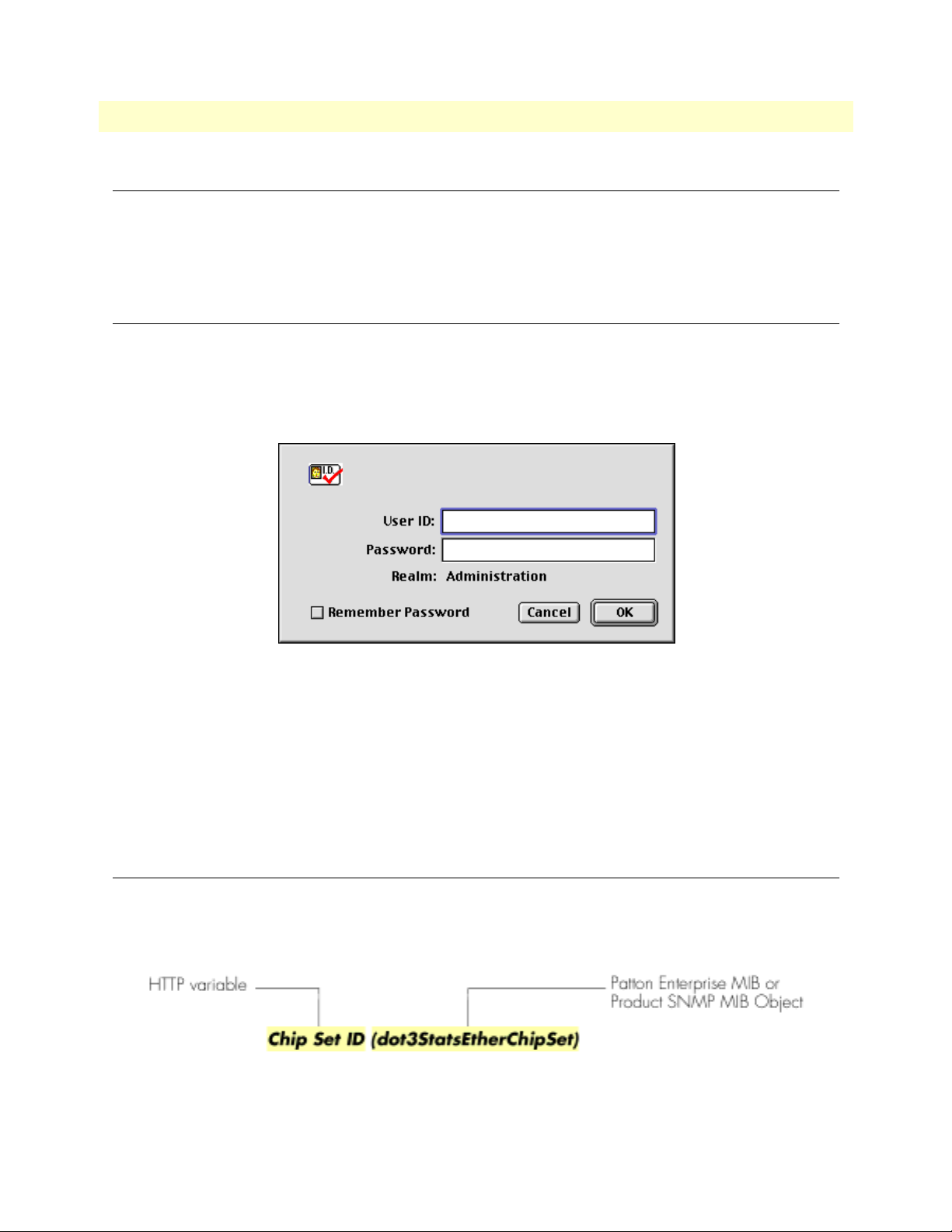
1 • Introduction Access Server Administrators’ Reference Guide
Introduction
You may configure the access server by using its internal HTTP/HTML Administration Pages. However, to
enter into the HTTP/HTML pages, you must first define the LAN Address Technique, LAN IP Address, and
LAN Subnet Mask for the access server. If you have not done so, please refer to the Getting Started Guide that
came with your access server.
Logging into the HTTP/HTML Administration Pages
To log into the HTTP/HTML Administration pages, you must enter the 4-octet Internet Protocol (IP) (for
example, http://your.server.ip.address) address as the Universal Resource Locator (URL) into a World-Wide Web
(WWW) browser. After you enter the IP address, the access server will ask for your user name and password as
shown in figure 1.
Figure 1. Access server login window
Your access server will accept the following default administrative passwords:
• superuser—this password carries full permission to change and view any parameters in the access server
• monitor—this password allows full viewing of any non-password oriented variables.
Note For security reasons, we recommend that you change these passwords
immediately after initial configuration.
HTTP/HTML and SNMP Object Format
In this document, we shall describe the variables found on each of the internal HTTP/HTML pages. This
description will include brief definitions of the Patton Enterprise MIB or SNMP MIB II object identifiers
wherever applicable. The format of the variables will resemble figure 2.
Figure 2. HTTP/HTML and SNMP object format
30 Introduction
Page 31

Access Server Administrators’ Reference Guide 1 • Introduction
Saving HTTP/HTML Object Changes
Sometimes you will need to save changes that you have made in the HTTP/HTML pages. Do the following to
make changes to read/write variables:
1. Select the appropriate
Modify screen.
2. Make changes to the desired parameter.
3. Click on the
4. Return to the
5. Click on the
Submit button.
HOME screen.
Record Current Configuration button.
Note Make sure you follow steps 1 through 5 when modifying the HTTP/
HTML pages. Otherwise, your changes will be lost when the access
server is power-cycled.
Saving HTTP/HTML Object Changes 31
Page 32

1 • Introduction Access Server Administrators’ Reference Guide
32 Saving HTTP/HTML Object Changes
Page 33

Chapter 2 Home
Chapter contents
Introduction..........................................................................................................................................................34
Operating Status Variables ....................................................................................................................................35
Active Calls (diActive) .....................................................................................................................................35
Peak Active Calls (diMaxActive) .....................................................................................................................35
Percentage CPU Idle (boxIdleTime) ...............................................................................................................35
DSPs Not Working (dspFailed) ......................................................................................................................35
Total DRAM Detected (boxDetectedMemory) ..............................................................................................35
Running Since Last Boot (sysUpTime) ...........................................................................................................35
Immediate Actions ................................................................................................................................................36
33
Page 34

2 • Home Access Server Administrators’ Reference Guide
Introduction
This chapter describes the HOME window—the first Administration Page that you see after logging into the
access server (see figure 3). From
base, save any system changes, or reset the system without power-cycling the server.
Note Clicking on the HOME link in the Configuration Menu pane will
return you to the
The
HOME window is divided into two panes: the Configuration Menu pane and the configuration/information
pane (see figure 3). The
Configuration Menu contains the links to the various access server subsystems, while
the configuration/information pane is where you can view status and other information, or make changes to
the system configuration. Unlike the Configuration Menu pane, which looks the same no matter which subsystem page you may move to, the configuration/information pane contents will change as you move from one
subsystem page to another.
HOME, you can monitor current system status, modify the Static User data-
HOME page from any other page.
Configuration Menu pane
Configuration/information pane
Figure 3. HOME page
34 Introduction
Page 35
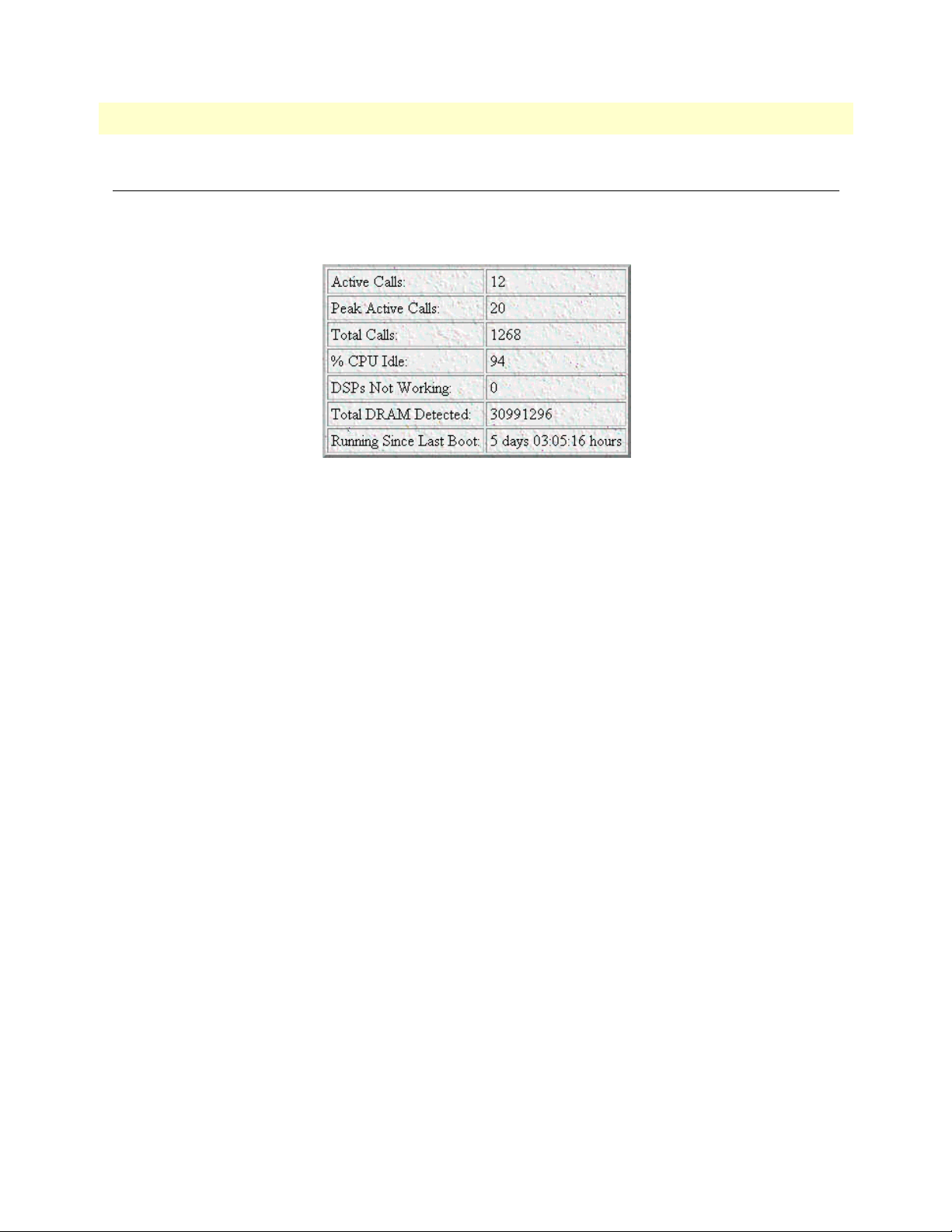
Access Server Administrators’ Reference Guide 2 • Home
Operating Status Variables
There are seven system variables which describe the immediate operating status access server. These variables
are shown in figure 4 and are described in the following sections.
Figure 4. STATUS menu
Active Calls (diActive)
This number, ranging from 0 to 60 displays the total number of calls being processed (connecting, dead,
authenticating, and so on) in the access server at the time the HOME page was displayed.
Peak Active Calls (diMaxActive)
The maximum number of active calls seen at one time since the access server was powered on.
Percentage CPU Idle (boxIdleTime)
This is an indication of the amount of system CPU power which is not being utilized by the access server. The
return value is a percentage of free CPU cycles since the last time the variable was read.
DSPs Not Working (dspFailed)
This number should always be zero. The DSP's in the access server are arranged as a resource pool and called
upon at ring-time. Therefore, if a DSP does not work, chances are you'll never know, as the access server will
automatically remove the faulty DSP from the resource pool. One symptom of a DSP failures is the access
server isn't handling as many calls as it should. A DSP may be taken out of service if it fails to respond to the
access server CPU. If a DSP isn’t available when a call comes in, the call will simply ring and not be answered.
Total DRAM Detected (boxDetectedMemory)
This number shows the total number of bits of installed and available DRAM.
Running Since Last Boot (sysUpTime)
This tells you how long the access server has been running since the it was last reset. It displays the number of
hours and rolls over after 1,193 hours (497 days).
Operating Status Variables 35
Page 36

2 • Home Access Server Administrators’ Reference Guide
Immediate Actions
There are several immediate actions (see figure 5) which, when in superuser mode, will cause the access server
to operate according to the descriptions in the following sections.
Figure 5. Immediate Actions buttons
• Record Current Configuration —clicking this button causes the current configuration to be stored in
FLASH memory. Any changes made to the access server configuration are stored in non-volatile RAM. This
allows the user to set the box up with a running configuration before commiting it to FLASH. Configuration changes become permanent when you select Record Current Configuration. You will lose all
changes not stored to FLASH the next time the access server is re-booted.
• Hard Reset—this button causes the access server to perform a cold restart. When you select Hard Reset,
the access server confirm that you want to execute this command. Then, the access server will disconnect all
current sessions, re-initialize the interfaces, and re-load configuration parameters from FLASH.
• Set Factory Default Configuration—this button clears out the configuration in FLASH and loads the
factory default parameters into FLASH memory. The factory default settings will not execute on the access
server until it is re-booted.
Note Set Factory Default Configuration will delete any routing infor-
mation, the access server’s Ethernet IP address, and any other site specific settings made for your particular installation. You will have to reenter the access server’s Ethernet IP address and netmask using the
front panel control port in order to use the HTTP/HTML Management pages.
36 Immediate Actions
Page 37

Chapter 3 Import/Export
Chapter contents
Introduction..........................................................................................................................................................38
Export Configuration ............................................................................................................................................38
Import Configuration............................................................................................................................................40
37
Page 38

3 • Import/Export Access Server Administrators’ Reference Guide
Introduction
The Import/Export function enables you to make a backup (or export) copy of your access server’s configuration parameters. By exporting the configurations, the saved files can quickly be loaded, or imported, into a
replacment access server—greatly speeding up the installation process should an access server need replacing.
Note All actions for Import/Export require superuser access privileges.
To import or export a configuration, click on
Import/Export main window (see figure 6).
Import/Export under the Configuration Menu to display the
Figure 6. Import/Export main window
Export Configuration
Note The exported configuration file is a text-format file. Do not try, how-
ever to edit the operating characteristics contained in the file.
Note The parameters that will be exported are the power-up settings as
they are stored in flash memory and may not be the current operating
parameters. To ensure that you export the most current parameters,
go to
HOME, then click on the Record Current Configuration button
under
Immediate Actions.
38 Introduction
Page 39

Access Server Administrators’ Reference Guide 3 • Import/Export
To export the flash configuration, click on the Export Flash link on the Import/Export main page. The access
server will display text configuration information resembling that shown in figure 7.
Figure 7. Typical access server flash memory configuration data
Export Configuration 39
Page 40
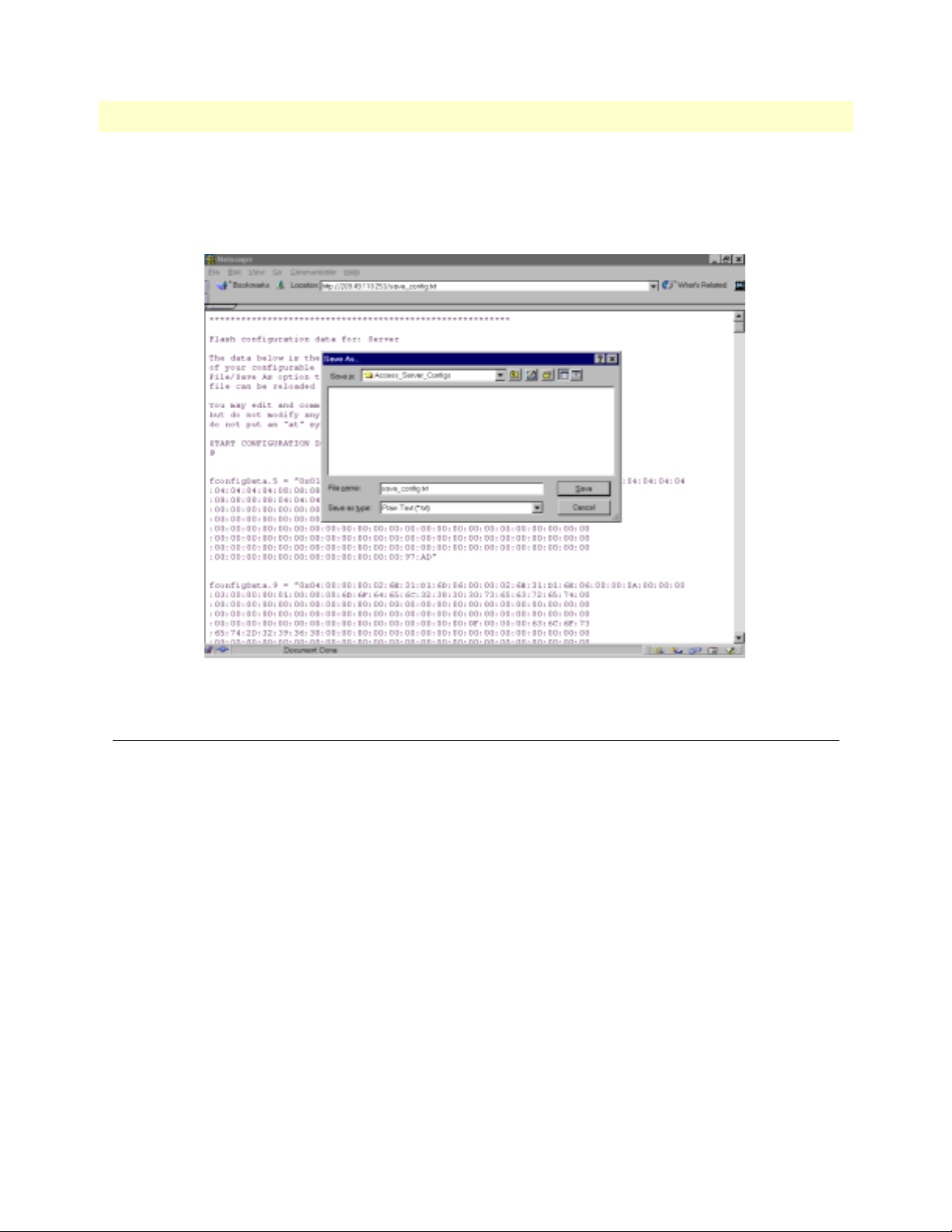
3 • Import/Export Access Server Administrators’ Reference Guide
To save the displayed data as a text file, select the Save option on your browser (see figure 8). For example,
under Netscape, select
parameters to a text file. Select the location where you want the file stored, type a file name, and click
File > Save As. A dialog box will display enabling you to save the contents of the export
Save.
Figure 8. Saving the access server flash memory configuration data as a text file
Import Configuration
To import a configuration file into the access server, type the complete path and filename for the configuration
file you wish to load or click on the
button (see figure 6 on page 38).
Upon successfully importing the file, the access server will display Configuration Load Complete, indicating that
the new operating parameters have been loaded into flash memory.
Click on
HOME under the Configuration Menu, then click on the Hard Reset button under Immediate Actions.
Note Do not select Record Current Configuration after importing configu-
ration parameters.
Browse… button to select the desired file, then click on the Submit Query
40 Import Configuration
Page 41

Chapter 4 Alarms
Chapter contents
Introduction..........................................................................................................................................................42
Displaying the Alarms window..............................................................................................................................42
Alarm Response Outputs ................................................................................................................................43
Minor Alarm Syslog Priority (minSyslogPriority) ......................................................................................44
Major Alarm Syslog Priority (majorSyslogPriority) ....................................................................................44
Minor Alarm Trap IP (minorTrapIp) ........................................................................................................44
Major Alarm Trap IP (majorTrapIp) .........................................................................................................44
Clear All Alarms ........................................................................................................................................44
Alarms ............................................................................................................................................................44
Alarm ID ...................................................................................................................................................44
Alarm Name .............................................................................................................................................44
Alarm Time ...............................................................................................................................................44
Alarm Count .............................................................................................................................................44
Generate Alarm .........................................................................................................................................44
Clear Alarm ...............................................................................................................................................44
Modify Response—Configuring the alarm response system...................................................................................45
Minor Alarm Syslog Priority (minSyslogPriority) ............................................................................................45
Major Alarm Syslog Priority (majorSyslogPriority) ..........................................................................................45
Minor Alarm Trap IP (minorTrapIp) .............................................................................................................45
Major Alarm Trap IP (majorTrapIp) ..............................................................................................................45
Modify Alarms—Configuring alarm severity levels................................................................................................46
41
Page 42
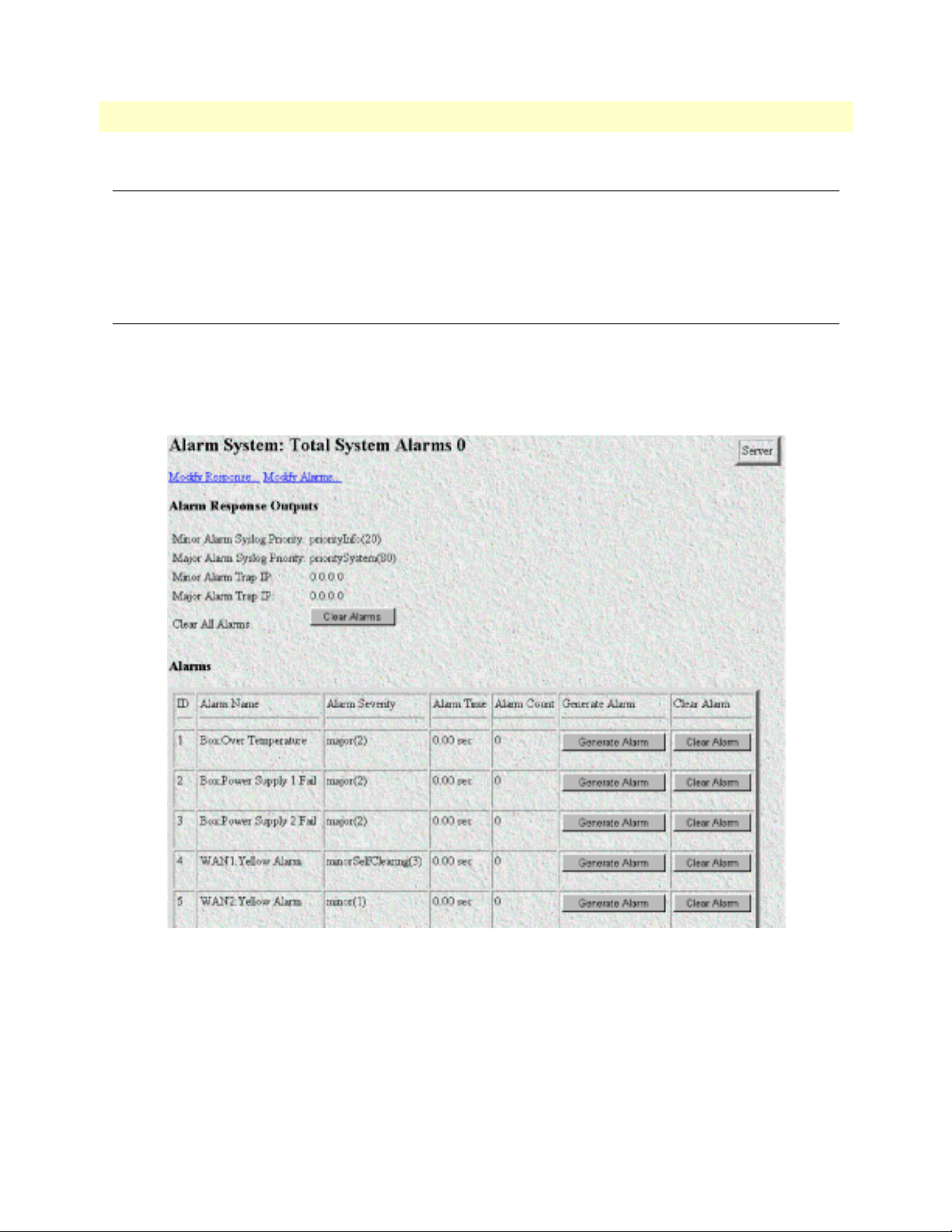
4 • Alarms Access Server Administrators’ Reference Guide
Introduction
The access server has an extensive alarm reporting system which enables users to configure, monitor, and test
major and minor alarms. The alarm system can be set to notify if equipment fails (for example, a power supply
failure) or if a T1/E1/PRI port malfunctions. There are 11 access server items that can be configured by the
user to generate alerts based on the condition of the access server.
Displaying the Alarms window
Click on Alarms under the Configuration Menu to to display the Alarm System main window (figure 9).
Note The system administrator can manually generate a specific alarm for
testing purposes or clear the alarm counters from the main window.
Figure 9. Alarms main window
42 Introduction
Page 43

Access Server Administrators’ Reference Guide 4 • Alarms
The access server has three methods to notify of an alarm condition:
• Front panel LED—The front panel ALARM LED has three states that indicate the presence and severity of
an alarm. The states are:
- Off—No alarm present
- Solid—Minor alarm
- Flashing—Major alarm.
Note The POWER LED will flash if a power supply failure alarm is
present.
• Administration web page indication—The Alarms window of the administration page uses red highlighting
to indicate which items are in an alarm state (see figure 10).
Figure 10. Sample alarm indication
• SYSLOG/SNMP—For external notification, the access server can be configured to send a SYSLOG mes-
sage or an SNMP TRAP to an external management host. To configure the alarm response for either SNMP
Traps or SYSLOG messages, click on the
Alarm Response link (go to “Modify Response—Configuring the
alarm response system” on page 45).
Besides enabling a user to view current alarm status, manually generate an alarm as a test, and clear the alarm
time and alarm count variables, the Alarms main window also contains links to the following:
• Modify Response—Clicking on this link takes you to a window where you can change how the SYSLOG/
SNMP function notifies remote users of an alarm (see “Modify Response—Configuring the alarm response
system” on page 45)
• Modify Alarms—Clicking on this link takes you to a window where you can change how the access server
perceives the severity of each alarm (“Modify Alarms—Configuring alarm severity levels” on page 46)
Alarm Response Outputs
Alarm Response Outputs display the current settings for handling alarm notification via SYSLOG/SNMP
messages. To change how the SYSLOG/SNMP function notifies remote users of an alarm, refer to “Modify
Response—Configuring the alarm response system” on page 45.
Displaying the Alarms window 43
Page 44

4 • Alarms Access Server Administrators’ Reference Guide
Minor Alarm Syslog Priority (minSyslogPriority)
Displays the SYSLOG priority of the minor alarm SYSLOG message, SYSLOG outputs that have a priority
less than this value will receive the minor alarm SYSLOG message.
Major Alarm Syslog Priority (majorSyslogPriority)
Displays the SYSLOG priority of the major alarm SYSLOG message, SYSLOG outputs that have a priority
less than this value will receive the minor alarm SYSLOG message.
Minor Alarm Trap IP (minorTrapIp)
Displays the IP address of a host system which is running a SNMP trap deamon. Minor alarm messages will be
sent to the system. If set to 0.0.0.0 then no trap message will be sent in response to a minor alarm
Major Alarm Trap IP (majorTrapIp)
Displays the IP address of a host system which is running a SNMP trap deamon. Major alarm messages will be
sent to the system. If set to 0.0.0.0 then no trap message will be sent in response to a minor alarm
Clear All Alarms
Clicking on this button resets all alarms to a non-alarm condition.
Alarms
This portion of the Alarms main window displays the alarm status table, where you can view current alarm status, manually generate an alarm as a test, and clear the alarm time and alarm count variables.
Alarm ID
This number identifies the alarm item.
Alarm Name
The alarm items are grouped into two categories: system and WAN trunk alarms. The system group category
lists access server temperature and power supply status. The WAN category monitors the T1/E1/PRI ports for
yellow and red alarms.
Alarm Time
The Alarm Time column displays the number of seconds the alarm has been activated.
Alarm Count
The Alarm Count column indicates how many times the alarm has occurred and is useful for monitoring selfclearing alarms.
Generate Alarm
For testing purposes, clicking the Generate Alarm button next to each alarm name will cause that alarm condition to be activated.
Clear Alarm
Clicking the Clear Alarm button resets the alarm to a non-alarm condition.
44 Displaying the Alarms window
Page 45
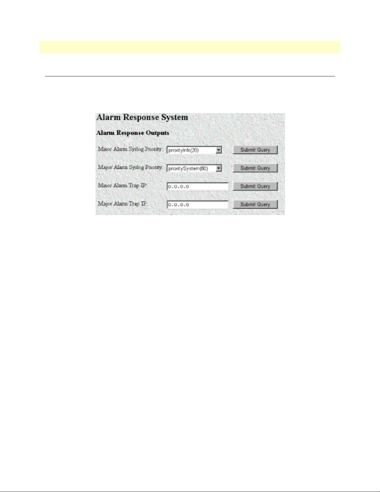
Access Server Administrators’ Reference Guide 4 • Alarms
Modify Response—Configuring the alarm response system
The alarm response outputs only effect external notification via SYSLOG/SNMP as the front panel ALARM
LED and the web administration pages will always indicate an alarm condition. The following user configuration items can be set to permit external notification of access server alarm conditions:
Figure 11. Alarm Response System window
Minor Alarm Syslog Priority (minSyslogPriority)
Sets the SYSLOG priority of the minor alarm SYSLOG message, SYSLOG outputs that have a priority less
than this value will receive the minor alarm SYSLOG message.
Major Alarm Syslog Priority (majorSyslogPriority)
Sets the SYSLOG priority of the major alarm SYSLOG message, SYSLOG outputs that have a priority less
than this value will receive the minor alarm SYSLOG message.
Minor Alarm Trap IP (minorTrapIp)
The IP address of a host system which is running a SNMP trap deamon. Minor Alarm messages will be sent to
the system. If set to 0.0.0.0 then no trap message will be sent in response to a minor alarm
Major Alarm Trap IP (majorTrapIp)
The IP address of a host system which is running a SNMP trap deamon. Minor Alarm messages will be sent to
the system. If set to 0.0.0.0 then no trap message will be sent in response to a minor alarm
Modify Response—Configuring the alarm response system 45
Page 46
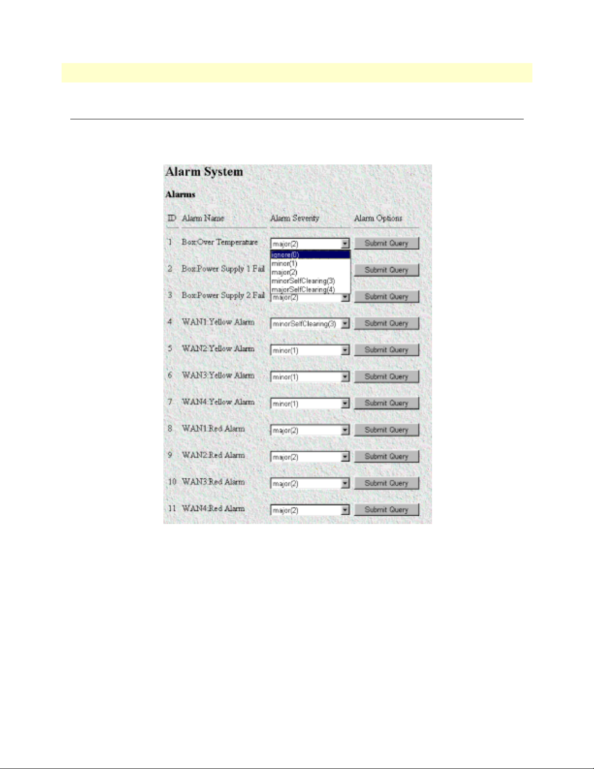
4 • Alarms Access Server Administrators’ Reference Guide
Modify Alarms—Configuring alarm severity levels
The Modify Alarms window (see figure 12) is where you can set the severity level each alarm condition generates and whether it can be a self-clearing condition.
Figure 12. Modify Alarms settings window
There are eleven alarms items that can be configured to generate alarm conditions. Each alarm item can be set
for one of the following severity levels:
• Ignore(0)—Do not generate an alarm
• Minor(1)—Generate a minor alarm that will not reset until the administrator manually clears it
• Major(2)—Generate a major alarm that will not reset until the administrator manually clears it
• MinorSelfClearing(3)—Generate a minor alarm that automatically clears if the alarm condition ceases
• MajorSelfClearing(4)—Generate a major alarm that automatically clears if the alarm condition ceases
46 Modify Alarms—Configuring alarm severity levels
Page 47

Access Server Administrators’ Reference Guide 4 • Alarms
Note For maximum flexibility, defining what constitues a major or minor
alarm is left up the administrator. Some examples of typical major
and minor include:
• Box Over-temperature—Major Alarm
• Power Supply Failure—Minor Alarm
• WAN Port Yellow Alarm—MajorSelfClearing
• WAN Port Red Alarm—MajorSelfClearing
To set an alarm, click on the drop-down menu for the desired alarm item, choose the new setting, then click on
Submit Query.
Modify Alarms—Configuring alarm severity levels 47
Page 48

4 • Alarms Access Server Administrators’ Reference Guide
48 Modify Alarms—Configuring alarm severity levels
Page 49

Chapter 5 Authentication
Chapter contents
Introduction..........................................................................................................................................................50
Displaying the Authentication window..................................................................................................................50
The Statistics section .............................................................................................................................................51
Validated authentications (auAuthenticationsValidTotal) ...............................................................................51
Validated via primary server (auAuthenticationsValidPrimary) .......................................................................51
Validated via secondary server (auAuthenticationsValidSecondary) .................................................................51
Validated via static database (auAuthenticationsValidStatic) ...........................................................................51
Denied authentications (auAuthenticationsDenied) ........................................................................................51
Primary server retries (auPrimaryServerRetrys) ................................................................................................51
Secondary server retries (auSecondaryServerRetrys) .........................................................................................51
Accounting server retries (auAccountingServerRetrys) .....................................................................................51
Primary server timeouts (auPrimaryServerTimeouts) .......................................................................................51
Secondary server timeouts (auSecondaryServerTimeouts) ................................................................................51
Accounting server timeouts (auAccountingServerTimeouts) ...........................................................................51
Maximum Response Time ..............................................................................................................................51
Last Response Time ........................................................................................................................................52
Setting Up Authentication.....................................................................................................................................52
Validation (auValidation) ................................................................................................................................52
Host Address (auHostAddress) ........................................................................................................................53
Secondary Host Address (auSecondaryHostAddress) .......................................................................................53
Host Port (auHostPort) ..................................................................................................................................53
Timeout (auTimeout) .....................................................................................................................................53
Retries (auRetries) ...........................................................................................................................................53
Secret (auSecret) ..............................................................................................................................................53
NAS Identifier (auNASIdentifier) ...................................................................................................................54
Accounting Address (auAcctAddress) ..............................................................................................................54
Secondary Accounting Address (auSecondaryAcctAddress) .............................................................................54
Accounting Port (auAcctPort) .........................................................................................................................54
Accounting Enable (auAccountingEnable) ......................................................................................................54
Radius Packet Format (auRadiusPacketFormat) ..............................................................................................54
Static User Authentication.....................................................................................................................................55
ID (suID) .......................................................................................................................................................55
Username (suUsername) .................................................................................................................................55
Password (suPassword) ....................................................................................................................................55
Service (suService) ...........................................................................................................................................55
Service IP (suServiceIP) ...................................................................................................................................57
Service Port (suServicePort) ............................................................................................................................57
Filter ID (suFilterId) .......................................................................................................................................57
49
Page 50

5 • Authentication Access Server Administrators’ Reference Guide
Introduction
Use the Authentication pages to set up system security and to provide specific users with access to appropriate
network services. This section describes the authentication parameters. The access server uses static and/or
RADIUS authentication to decide which dial-in users can access the system (refer to Appendix A, “Supported
RADIUS Attributes” for a full list of RADIUS attributes).
Displaying the Authentication window
Do the following:
1. Click on
Authentication under the Configuration Menu (see figure 13).
Authentication
Modify
Figure 13. Authentication main screen
50 Introduction
Page 51

Access Server Administrators’ Reference Guide 5 • Authentication
2. Select Modify to set up or change access server Authentication parameters.
The Statistics section
The Statistics section of the main Authentication screen lists running totals of statistics for RADIUS and Static
User logins gathered since the last access server reset.
Validated authentications (auAuthenticationsValidTotal)
The total number of validated authentications since the last access server reset.
Validated via primary server (auAuthenticationsValidPrimary)
The number of authentications validated by the primary RADIUS authentication server since the last access
server reset.
Validated via secondary server (auAuthenticationsValidSecondary)
The number of authentications validated by the secondary RADIUS authentication server since the last access
server reset.
Validated via static database (auAuthenticationsValidStatic)
The number of authentications validated by the Static User database since the last access server reset.
Denied authentications (auAuthenticationsDenied)
The total number of authentication attempts requested but denied since the last access server reset.
Primary server retries (auPrimaryServerRetrys)
The number of times the access server needed to make subsequent requests for a call to the primary RADIUS
authentication server.
Secondary server retries (auSecondaryServerRetrys)
The number of times the access server needed to make subsequent requests for a call to the secondary RADIUS
authentication server.
Accounting server retries (auAccountingServerRetrys)
The number of times the access server needed to make subsequent accounting requests for a call.
Primary server timeouts (auPrimaryServerTimeouts)
The total number of authentication timeouts by the primary RADIUS authentication server.
Secondary server timeouts (auSecondaryServerTimeouts)
The total number of authentication timeouts by the secondary RADIUS authentication server.
Accounting server timeouts (auAccountingServerTimeouts)
The total number of accounting timeouts by the primary RADIUS accounting server.
Maximum Response Time
The maximum time it has taken for authentication to be completed since the server rebooted.
The Statistics section 51
Page 52
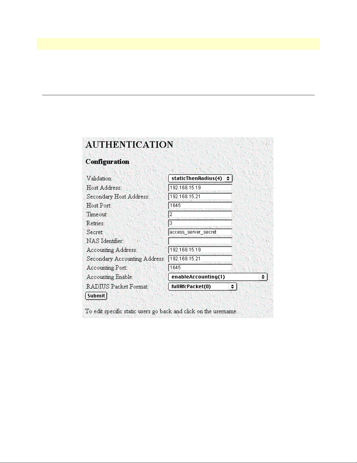
5 • Authentication Access Server Administrators’ Reference Guide
Last Response Time
The time taken for the last authentication to be completed.
Setting Up Authentication
After selecting Modify from the main Authentication screen, you may set up or change authentication parameters for both RADIUS users and Static users. After configuring the Validation method (see “Validation (auValidation)” below), configure the additional parameters as shown in figure 14 to configure RADIUS parameters.
See “Static User Authentication” on page 55 to set up Static users.
Figure 14. Authentication Configuration screen
Validation (auValidation)
Selects how the access server will authenticate an incoming call. Select from:
• No Validation(0)—Select this to allow un-authenticated calls into the access server, and on to your LAN,
using the default service.
• static Users(1)—Use the access server internal user database only to authenticate. Static users are simply
users and passwords entered into the access server’s internal users database.
• radius Users(2)—Use RADIUS to authenticate and provision user services. RADIUS is a client-server sys-
tem developed to manage the flexible requirements of remote dial-in users. The RADIUS protocol is specified under RFC 2138 for authentication and RFC 2139 for accounting. RADIUS servers are available
52 Setting Up Authentication
Page 53

Access Server Administrators’ Reference Guide 5 • Authentication
as freeware for most computer platforms and is an excellent method for managing user dial-in security.
Any RADIUS entries will require an associated server to process authentication requests from the access
server or the access server will reject users access. For more information about RADIUS, see RADIUS User
Authentication, below.
• tacacs Users(3)—This feature is not currently available
• static Then RADIUS(4)—Check the internal user database first, if no match is found, then use RADIUS
to authenticate and provision user services.
• static Then Tacacs(5)— Check the internal user database first, if no match is found, then use TACACS to
authenticate and provision user services. Not currently implemented.
Note The following options apply only when using an external authentica-
tion server.
Host Address (auHostAddress)
Tells the access server the IP address of the primary external authentication server. This must be the IP address
as the access server will not resolve a Fully Qualified Domain Name.
Secondary Host Address (auSecondaryHostAddress)
When using a remote authentication server (RADIUS) this variable provides an alternative server IP address.
Host Port (auHostPort)
This variable tells the access server which UDP port to use when connecting to the host specified in the Host
Address variable. The RADIUS standard, as per RFC 2138, specifies port 1812 for RADIUS authentication.
Some older installations of RADIUS use port 1645.
Timeout (auTimeout)
This option specifies the time, in seconds, before the access server will retransmit an authentication request to
an external authentication server.
Retries (auRetries)
This option specifies the number of times the access server will resend an authentication request to a RADIUS
server after a TIMEOUT occurs. If this number is exceeded then the secondary host will be tried. If this number is exceeded by the secondary host, the user will be rejected.
Secret (auSecret)
The Secret variable sets the shared secret between the authentication client (access server) and the authentication server (RADIUS). It is used to encrypt an authentication request and to decrypt an incoming reply from
the server. The secret on the access server and the RADIUS server must match and must be 15 or fewer printable, non space, ASCII characters.
Note The same secret word must used on the access server and in the
RADIUS clients file.
Setting Up Authentication 53
Page 54

5 • Authentication Access Server Administrators’ Reference Guide
NAS Identifier (auNASIdentifier)
This variable is used to identify the access server to the remote authentication server. If this option is blank,
then the access server will use the it’s IP address to identify itself to the remote server.
Accounting Address (auAcctAddress)
This is the IP address of the accounting server. RADIUS also allows for the recording of accounting information.
Secondary Accounting Address (auSecondaryAcctAddress)
When using a remote accounting server (such as RADIUS Accounting) this variable provides the IP address of
the accounting server.
Accounting Port (auAcctPort)
This is the UDP port on the accounting server specified in Acct Address that the access server should use to
transfer accounting information. RFC 2139 calls out the port of 1813 as the standard RADIUS accounting
port. Some older implementations of RADIUS use port 1646 as the accounting port.
Accounting Enable (auAccountingEnable)
This is a switch that allows the enabling or disabling the reporting of accounting information on the access
server. The following options are available:
• enableAccounting—Begin accounting of RADIUS authenticated users.
• disableAccounting—Disable the accounting feature.
• enableAccounting-no validation—When a response is received from either the authentication or the
accounting server it is validated using the defined secret. If the secret does not match, the reply packet is
dropped just as if it never existed.
Early versions of the Livingston RADIUS server used a method for encoding the accounting reply packet
that was incorrect. Accounting replies from these servers would therefore be dropped because they could
not be authenticated, eventually resulting in timeouts and shutting the call down with the reason authenAc-
countingTimeout. As a workaround for this issue, the state enableAccountingNoValidation—which does not
check for valid encoding on the accounting reply packet—was added as an option.
Radius Packet Format (auRadiusPacketFormat)
The following options are available:
• fullrfcPacket—The accept request packet includes Calling-Station-Id and Service-Type RADIUS attributes.
• minimumrfcPacket—This setting does not include Calling-Station-Id and Service-Type RADIUS
attributes.
54 Setting Up Authentication
Page 55

Access Server Administrators’ Reference Guide 5 • Authentication
Static User Authentication
To view or modify the static users in the internal user database, click on Authentication in the Configuration
Menu. The Authentication window displays. Scroll down until Static User Identification is displayed (see
figure 15).
Static users consist of usernames and passwords entered into the access server’s internal users database. You can
have up to 111 static users in the access server database.
You must have superuser-level access to make changes to the static users database.
The following sections describe each of the variables found in the
Figure 15. Static User Identification setup
Static User Identification section.
ID (suID)
Identifies the entry in the table of users. For the next user, select the next unused number. If you select a number that is already displayed in the Static User Identification table, you will overwrite a current entry in user
database.
Username (suUsername)
This is a unique name, to be provided at login time.
Note There is a 19-character limit on the username length.
Password (suPassword)
This is the password that corresponds to the ID being edited.
Service (suService)
This option instructs the access server on how to service the incoming call. Select from:
• default—This is the default service as specified under Dial-In (see Chapter 7, “Dial In”). We recommend
that you select default.
• admin—Not currently implemented.
• monitor—Not currently implemented.
Static User Authentication 55
Page 56

5 • Authentication Access Server Administrators’ Reference Guide
• rlogin—Causes the access server to rlogin into another host. See “Service IP (suServiceIP)” on page 57 for
information on configuring the remote host IP addresss.
• telnet—Causes the access server to telnet into another host.
• tcpraw—All 8 bits are passed unchecked and unaltered.
• ppp—Access server will try to negotiate a PPP session.
• cppp—Access server will try to negotiage a Compressed-PPP session.
Note If a user attempts to login in using a different service than the one he
or she has been provided, the access server will reject the user. The
exception to this is CPPP which will revert to PPP if CPPP is not
available on the client.
• slip—Access server will negotiate a SLIP connection.
• cslip—Access server will negotiate a Compressed-SLIP connection.
• dialout—Access server will give a dialout connection. The dialout connection is an AT command set
driven connection into one of the access server modems. On line help is provided by typing at help <cr>.
• vpn—This option is currently not supported.
Note If a user attempts to login in using a different service than the one he
or she has been provided, the access server will reject the user. The
exception to this is CPPP which will revert to PPP if CPPP is not
available on the client.
Note All changes made to the running configuration must be saved to
FLASH by selecting Record Current Configuration under
diate Actions on the HOME page of the access server. Failure to do so
will cause all configuration information to be lost the next time the
access server is re-booted.
After the user information has been entered, click Submit.
Imme-
56 Static User Authentication
Page 57

Access Server Administrators’ Reference Guide 5 • Authentication
To modify or further configure the user, click the username you just created to display the Static User window
(see figure 16). Refer to the following sections while modifying the Static User settings. When you are finished,
click Submit to store the changes.
Figure 16. Static User settings window
Service IP (suServiceIP)
This is the IP of the RLogin or Telnet host, or the static IP address assigned to the user. This is determined by
the option selected in
Service
(see “Service (suService)” on page 55).
Service Port (suServicePort)
This is the port number to connect to the service host. If the number is 0, the access server will use the default
values for Telnet (port number 23) and RLogin (port number 513).
Note After you have submitted all changes, click on the HOME link in the
Configuration Menu. Once there, click on the Record Current Con-
figuration button (located under
Immediate Actions) to save the
changes to FLASH memory on the access server.
All changes made to the running configuration must be saved to
FLASH memory. Failure to do so will cause all configuration information to be lost the next time the access server is re-booted.
Filter ID (suFilterId)
This is the ID of the filter assigned to the static user. A filter controls packets that can be sent or received by the
dial-in user to which it is applied. Only one filter can be assigned to a user defined in the static user authentication database.
Note Explicitly assigning a filter to a static user will keep default dial-in
filters from being applied.
Static User Authentication 57
Page 58

5 • Authentication Access Server Administrators’ Reference Guide
58 Static User Authentication
Page 59

Chapter 6 DAX
Chapter contents
Introduction..........................................................................................................................................................60
Configuring the DAX............................................................................................................................................60
Circuit Type (daxClockMode) ........................................................................................................................60
Main Reference (daxClockMainRef) ...............................................................................................................61
Fallback Reference (daxClockFallbackRef) ......................................................................................................61
Clock Status (daxClockFailure) .......................................................................................................................62
59
Page 60

6 • DAX Access Server Administrators’ Reference Guide
Introduction
The digital cross-connect (DAX) link allows configuration of the access servers’ digital cross-connect that manages the time slots and clocking between the WAN ports.
The access server uses a single clock source for all WAN ports. Therefore, to avoid data loss caused by variations
in network timing, each access server should terminate WAN connections from a single timing provider. WAN
connections from multiple timing providers can be terminated in the access server if all the providers source
their timing from the same stratum clock or if the access server provides the network clock.
Click on
DAX under the Configuration Menu to display the DAX main window (see figure 17).
Figure 17. DAX main window
Configuring the DAX
There are three variables to select when configuring the DAX circuit:
• Circuit Type—Defines the overall clocking scheme for the entire access server (refer to “Circuit Type (dax-
ClockMode)”
• Main Reference—Determines which WAN link supplies the clock for the system (refer to “Main Reference
(daxClockMainRef)” on page 61)
• Fallback Reference—Enables the configuration of a back-up clock reference should the Main Reference fail
(refer to “Fallback Reference (daxClockFallbackRef)” on page 61)
Circuit Type (daxClockMode)
Defines the overall clocking scheme for the entire access server. For each circuit a selection must be made as to
the overall clocking scheme of the entire system. If your system has only one circuit displayed, then that circuit
must be set to Master.
The following settings are available:
• master(1)—The master device is responsible for providing the master system clock in synchronization with
one of its references. If your access server has only one circuit, then this setting must be Master.
• secondary(2)—The secondary circuit provides the master system clock if the master circuit fails.
• slave(3)—Slave devices provide the system clock references for use by the master or secondary.
60 Introduction
Page 61

Access Server Administrators’ Reference Guide 6 • DAX
Main Reference (daxClockMainRef)
The main reference parameter determines which WAN link will supply the clock for the system.
The following settings are available:
• none(0)—No clock selection. This would be used in conjunction with either a secondary or slave circuit.
• local-ref-1(1)—Use WAN Port 1 for primary timing. Generally the first WAN connection will be used as
the main reference.
• local-ref-2(2)—Use WAN Port 2 for primary timing. Generally the second WAN connection will be used as
the fallback reference (see “Fallback Reference (daxClockFallbackRef)”).
• local-ref-3(3)—Use WAN Port 3 for primary timing.
• local-ref-4(4)—Use WAN Port 4 for primary timing.
• local-ref-5(5)—Use WAN Port 5 for primary timing.
• local-ref-6(6)—Use WAN Port 6 for primary timing.
• local-ref-7(7)—Use WAN Port 7 for primary timing.
• local-ref-8(8)—Use WAN Port 8 for primary timing.
• netref-1(101)—Use to obtain system timing from a slave circuit.
• netref-2(102)—Use to obtain system timing from a slave circuit.
• oscillator(200)—Use internal free-run oscillator for the system clock
Fallback Reference (daxClockFallbackRef)
The fallback reference enables the configuration of a back-up clock reference should the main reference fail.
The following settings are available:
• none(0)—No clock selection. This would be used in conjunction with either a secondary or slave circuit.
• local-ref-1(1)—Use WAN Port 1 for secondary timing. Generally the first WAN connection will be used as
the main reference.
• local-ref-2(2)—Use WAN Port 2 for secondary timing. Generally the second WAN connection will be used
as the fallback reference. If there is only one WAN connection, then the fallback reference should be set to
oscillator.
• local-ref-3(3)—Use WAN Port 3 for secondary timing.
• local-ref-4(4)—Use WAN Port 4 for secondary timing.
• local-ref-5(5)—Use WAN Port 5 for secondary timing.
• local-ref-6(6)—Use WAN Port 6 for secondary timing.
• local-ref-7(7)—Use WAN Port 7 for secondary timing.
• local-ref-8(8)—Use WAN Port 8 for secondary timing.
• netref-1(101)—Use to obtain system timing from a slave circuit.
Configuring the DAX 61
Page 62

6 • DAX Access Server Administrators’ Reference Guide
• netref-2(102)—Use to obtain system timing from a slave circuit.
• oscillator(200)—Use internal free-run oscillator for the system clock
Clock Status (daxClockFailure)
The clock status indicates alarm conditions relating to the system clock. If there are no alarms, the DAX page
will indicate No Alarms (see figure 17 on page 60). Should one or more alarms be present, an Alarms Present
message will be displayed with the following list of potention clock failures (figure 18).
• no-failures(0)—No alarms present
• main-ref-fail(1)—The main clock reference has failed
• fallback-ref-fail(2)—The fall back clock reference has failed
• master-system-clock-fail(4)—The Master System clock has failed
• secondary-system-clock-fail(8)—The Secondary System clock has failed.
Figure 18. DAX Clock Status alarm condition
62 Configuring the DAX
Page 63

Chapter 7 Dial In
Chapter contents
Introduction..........................................................................................................................................................67
Dial In main window ............................................................................................................................................68
Active Calls (diActive) .....................................................................................................................................68
Peak Active Calls (diMaxActive) .....................................................................................................................68
Total Calls (diTotalCallAttempts) ...................................................................................................................68
Call ID (diactIndex) ........................................................................................................................................68
Call ID (diactIndex) ........................................................................................................................................68
ML ID (diactMultiIndex) ...............................................................................................................................68
User (diactusername) ......................................................................................................................................68
State (diactState) .............................................................................................................................................68
Duration (diactSessionTime) ..........................................................................................................................68
Disconnect Reason (diactTerminateReason) ...................................................................................................69
Modulation (diactModulation) .......................................................................................................................69
Connect Speed (diactTxSpeed) .......................................................................................................................69
Dial In Details.......................................................................................................................................................70
Dial In Modify window.........................................................................................................................................71
Modify Login ..................................................................................................................................................72
IP Address Pool (diIpPool) ........................................................................................................................72
Login Technique (diLoginTechnique) .......................................................................................................72
Username Prompt (diUsernamePrompt) ...................................................................................................73
Password Prompt (diPasswordPrompt) ......................................................................................................73
Initial Banner (diBanner) ..........................................................................................................................73
Modify Service ................................................................................................................................................73
Default Service (diService) .........................................................................................................................73
Default IP Service (diServiceIP) ................................................................................................................73
Default Service Port (diServicePort) ..........................................................................................................74
Force Next Hop (diForceNextHop) ..........................................................................................................74
Modify Domain Name Server .........................................................................................................................74
Primary Domain Name Server (diPrimaryDNS) .......................................................................................74
Secondary Domain Name Server (diSecondaryDNS) ................................................................................74
Primary WINS (diPrimaryWINS) .............................................................................................................74
Secondary WINS (diSecondaryWINS) ......................................................................................................74
Modify Attempts .............................................................................................................................................75
Failure Banner (diFailureBanner) ..............................................................................................................75
Login Attempts Allowed (diAllowAttempts) ..............................................................................................75
Modify Configuration .....................................................................................................................................75
Link Compression (diLinkCompression) ..................................................................................................76
Default Max Receive Unit (diConfigInitialMRU) .....................................................................................76
Allow Magic Number Negotiation (diConfigMagicNumber) ....................................................................76
63
Page 64

7 • Dial In Access Server Administrators’ Reference Guide
Frame Check Sequence Size (diConfigFcsSize) ..........................................................................................76
Compression (diIpConfigCompression) ....................................................................................................76
MultiLink (diConfigMultilink) .................................................................................................................76
MultiBox (diConfigMMP) ........................................................................................................................76
Modify Maximum Time .................................................................................................................................77
Maximum Session Time (min) (diSessionTimeout) ..................................................................................77
Maximum Idle Time (min) (diIdleTimeout) .............................................................................................77
Time to login (sec) (diLoginTimeout) .......................................................................................................77
Call History Timeout (min) (diLingerTime) .............................................................................................77
Modify Modem Configuration .......................................................................................................................78
V34 (diModemV34Enable) .......................................................................................................................78
V32 (diModemV32Enable) .......................................................................................................................78
V22 (diModemV22Enable) .......................................................................................................................78
V21(diModemV21Enable) ........................................................................................................................79
MaxSpeed (diModemMaxSpeed) ..............................................................................................................79
MinSpeed (diModemMinSpeed) ...............................................................................................................79
Guard Tone (diModemGuardTone) .........................................................................................................79
CarrierLossDuration (diModemCarrierLossDuration) ..............................................................................79
Billing Delay (diBillingDelay) ...................................................................................................................79
Retrain (diModemRetrain) ........................................................................................................................79
TxLevel (diModemTxLevel) ......................................................................................................................79
Protocol (diModemProtocol) ....................................................................................................................80
Compression (diModemCompression) ......................................................................................................80
Dial In User Statistics window...............................................................................................................................81
Call Identification ...........................................................................................................................................82
Call ID: (diactIndex) .................................................................................................................................82
State (diactState) .......................................................................................................................................82
Username (diactUsername) .......................................................................................................................82
Password (diactPassword) ..........................................................................................................................82
Shared Unique ID (diactMultiIndex) ........................................................................................................82
Protocol (diactProtocol) ............................................................................................................................82
Security Level (diactAccessLevel) ...............................................................................................................83
DSP Link (diactDSPIndex) .......................................................................................................................83
Interface Link (diactIFIndex) ....................................................................................................................83
WAN Link (diactLinkIndex) .....................................................................................................................83
Time Slot (diactSlotIndex) ........................................................................................................................83
IP Address (diactIP) ..................................................................................................................................83
Port # on Remote Machine (diactPort) .....................................................................................................83
Session ............................................................................................................................................................83
Start time of call (diactSessionStartTime) ..................................................................................................83
Time Call Is/Was Active (diactSessionTime) .............................................................................................83
Minutes Until Timeout (diactRemainingIdle) ...........................................................................................83
Time Left In Session (diactRemainingSession) ..........................................................................................83
Termination Reason (diactTerminateReason) ...........................................................................................84
64
Page 65

Access Server Administrators’ Reference Guide 7 • Dial In
State at termination (diactTerminateState) ................................................................................................87
PPP Statistics ..................................................................................................................................................87
Bad Address (diStatBadAddresses) .............................................................................................................88
Bad Controls (diStatBadControls) .............................................................................................................88
Packets Too Long (diStatPacketTooLongs) ...............................................................................................88
Bad Frame Check Sequences (diStatBadFCSs) ..........................................................................................88
LCP Statistics ..................................................................................................................................................88
Local MRU (diStatLocalMRU) .................................................................................................................88
Remote MRU (diStatRemoteMRU) .........................................................................................................88
Local Multilink MRRU (diStatLcpLocalMRRU) ......................................................................................88
Remote Multilink MRRU (diStatLcpRemoteMRRU) ..............................................................................88
LCP Authentication (LCPAuthOptions) ...................................................................................................88
ACC Map (diStatLocalToPeerACCMap) ..................................................................................................89
Peer-Local ACC Map (diStatPeerToLocalACCMap) ................................................................................89
Local-Remote PPP Protocol Comprsn (diStatLocalToRemoteProtComp) ................................................89
Remote-Local PPP Protocol Comprsn (diStatRemoteToLocalProtComp) ................................................89
Local-Remote AC Comprsn (diStatLocalToRemoteACComp) .................................................................89
Remote-Local AC Comprsn (diStatRemoteToLocalACComp) .................................................................89
Transmit Frame Check Seq. Size (diStatTransmitFcsSize) .........................................................................90
Receive Frame Check Seq. Size (diStatReceiveFcsSize) ..............................................................................90
IP ....................................................................................................................................................................90
Operational Status (diIpOperStatus) .........................................................................................................90
Local-Remote VJ Protocol Comprsn (diIpLocalToRemoteCompProt) .....................................................90
Remote-Local VJ Protocol Comprsn (diIpRemoteToLocalCompProt) .....................................................90
Remote Max Slot ID (diIpRemoteMaxSlotId) ..........................................................................................90
Local Max Slot ID (diIpLocalMaxSlotId) ..................................................................................................91
Force Next Hop(diForceNextHop) ...........................................................................................................91
Filters (diStatIpFilterAtoJ) .........................................................................................................................91
Phone .............................................................................................................................................................91
Number Called (diactNumberDialed) .......................................................................................................92
Number Called From (diactCallingPhone) ................................................................................................92
Data ................................................................................................................................................................92
Octets Sent (diactSentOctets) ....................................................................................................................92
Octets Received (diActReceivedOctets) .....................................................................................................92
Packets Sent (diactSentDataFrames) ..........................................................................................................92
Packets Received (diactReceivedDataFrames) ............................................................................................92
Bad Packets (diactErrorFrames) .................................................................................................................92
Physical Layer .................................................................................................................................................92
Connection Modulation (diactModulation) ..............................................................................................92
Transmit Connection Speed (diactTxSpeed) .............................................................................................93
Receive Connection Speed (diactRxSpeed) ................................................................................................93
Error Correction (diactErrorCorrection) ...................................................................................................93
Data Compression Protocol (diactCompression) .......................................................................................93
Modulation Symbol Rate (diactSymbolRate) ............................................................................................93
65
Page 66

7 • Dial In Access Server Administrators’ Reference Guide
Locally Initiated Renegotiates (diactLocalRenegotiates) .............................................................................93
Locally Initiated Retrains (diactLocalRetrains) ..........................................................................................93
Remote Initated Renegotiates (diactRemoteRenegotiates) .........................................................................93
Remote Initated Retrains (diactRemoteRetrains) .......................................................................................93
66
Page 67

Access Server Administrators’ Reference Guide 7 • Dial In
Introduction
The Dial In main window (see figure 19) is where you can change or view items that are associated with the
user dialing in—including call statistics, type of service used, modem specific statistics, as well as configuration
parameters for login, service, domain name service, login attempts, configuration of link, maximum time, and
modem configuration.
Click on
Dial In under the Configuration Menu to display the Dial In main window.
The Dial In window contains the following items:
• Statistics for individual users (for example, users jill
, jeff, and jay, as shown in figure 19). For more informa-
tion about the statistics displayed on the Dial In main window, refer to “Dial In main window” below.
To view or modify individual user settings, select an active user in the
wanted to modify user jill, you would click on the
online(6) link next to jill’s username.) For more informa-
State column (for example, if you
tion about modifying individual user settings, refer to “Dial In User Statistics window” on page 81.
Details link—clicking on the Details… link takes you to the page where you can see how the system is cur-
•
rently set up to handle dial in users. For more information about the
Details page, refer to “Dial In Details”
on page 70.
Modify link—clicking on the Modify… link takes you to the page where you can make global changes to
•
items that are associated with the user dialing in—including type of service used, configuration parameters
for login, service, domain name service, login attempts, configuration of link, maximum timeouts, and
modem configuration. For more information about the
Modify page, refer to “Dial In Modify window” on
page 71.
Figure 19. Dial In main window
Introduction 67
Page 68

7 • Dial In Access Server Administrators’ Reference Guide
Dial In main window
The Dial In window displays statistics for individual users. This window shows currently attached users, the
users state, and time that the user has been on access server. This window can also display recently disconnected
sessions. The following sections explain the meaning of each statistic.
Active Calls (diActive)
The total number of active calls and calls that are initiating. If no calls are active then you will not see any User
State Session Time access server parameters.
Peak Active Calls (diMaxActive)
The maximum number of active calls seen at one time since the unit was powered up.
Total Calls (diTotalCallAttempts)
The total number of calls attempted since the last boot of the box.
Call ID (diactIndex)
Unique identification of this active call for internal use.
Call ID (diactIndex)
Subsequent calls in a multilink PPP/ISDN call refer to this ID as a pointer to the bundlehead or originating
call.
ML ID (diactMultiIndex)
Subsequent calls in a multilink PPP/ISDN call have a pointer to the bundlehead or originating call.
User (diactusername)
The user name that the caller entered. This can be a static user or a radius user’s login name.
State (diactState)
As the call comes into the access server it can be in one of five states.
• Ringing—The call has been recognized by the access server and is in process of going off hook.
• Connecting—The unit has assigned a DSP to the incoming call and is now in the process of negotiation of
the type of modulation—V.34, V.32, ISDN, or 56K.
• Authenticating—The access server is in the process of verifying the users passwords by using static or
RADIUS authentication.
• Online—The access server has completed authentication and we are ready to access the Internet.
• Dead—The user has been disconnected and this message will go away after the linger time has esxpired.
• Bury—Kill the call and remove it from the dial-in main window.
Duration (diactSessionTime)
The number of seconds this call was/is active. Time in seconds the user has been connected.
68 Dial In main window
Page 69

Access Server Administrators’ Reference Guide 7 • Dial In
Disconnect Reason (diactTerminateReason)
The reason a call was disconnected.
Modulation (diactModulation)
The modulation of the link:
• unknown(0)
• v21(1)—V.21 modulation
• v22(2)—V.22 modulation
• v32(3)—V.32 modulation
• v34(4)—V.34 modulation
• k56(5)—K56 Flex modulation
• x2(6)—X.2 modulation
• v90(7)—V.90 modulation
• v110(8)—V.110 modulation (not currently implemented)
• isdn64(9)—ISDN 64 modulation
• isdn56(10)—ISDN 56 modulation (not currently implemented)
• 12tp(11)—12tp tunnelled multilink call
Connect Speed (diactTxSpeed)
The connected speed of the link.
Dial In main window 69
Page 70

7 • Dial In Access Server Administrators’ Reference Guide
Dial In Details
The Dial In Details window (see figure 20) shows how the system is currently set up to handle dial in users. To
view this page, select
access server parameters. To modify the Dial In access server parameters, click on the Modify… link. For more
information about modifying Dial In settings, refer to “Dial In Modify window” on page 71.
Details from the main Dial In window. Scroll down the window to view additional Dial In
Figure 20. Dial In Details window
70 Dial In Details
Page 71
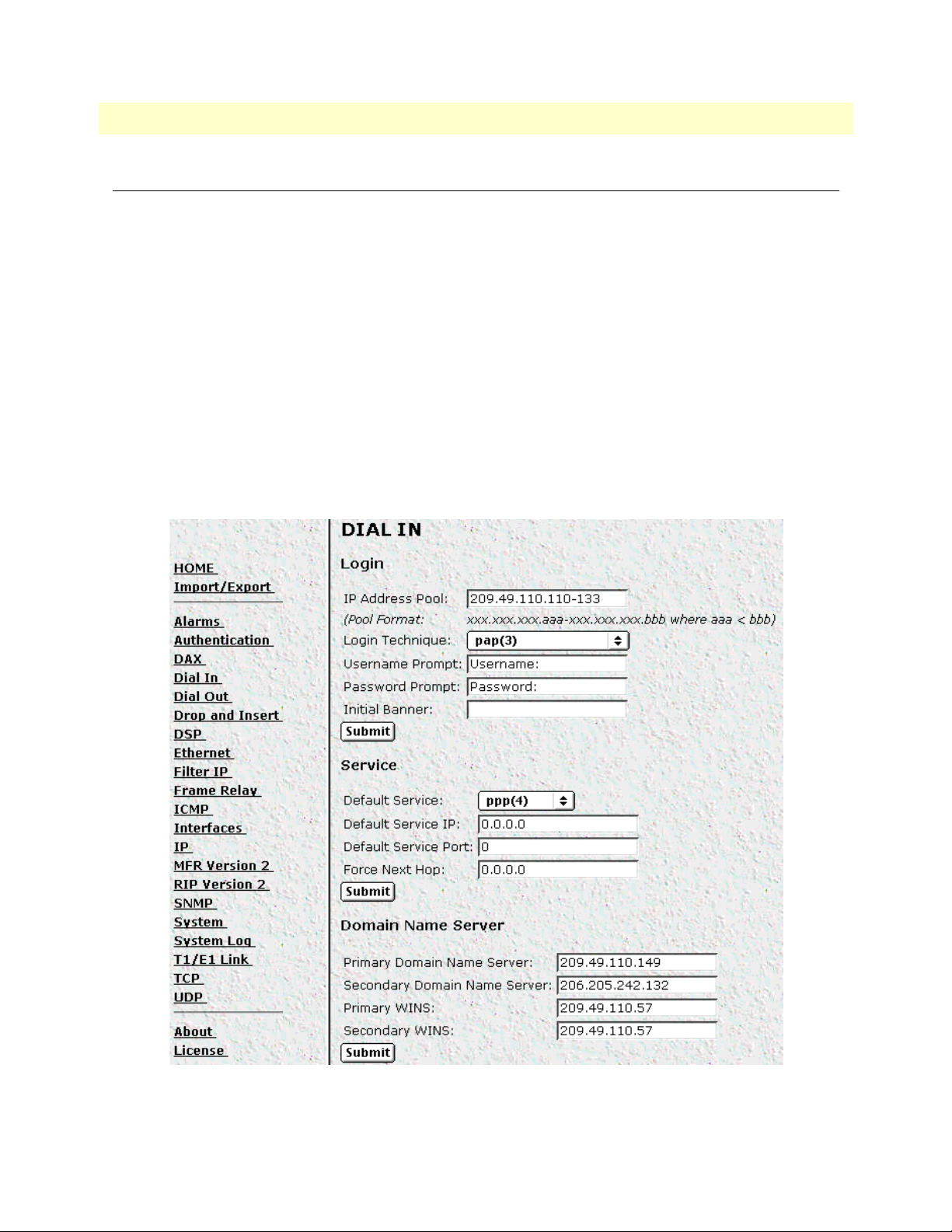
Access Server Administrators’ Reference Guide 7 • Dial In
Dial In Modify window
The Dial In Modify window (see figure 21) is where you can make changes to the following:
• Login access server parameters (see “Modify Login”)
• User login services (see “Modify Service” on page 73)
• Primary and secondary domain name servers (see “Modify Domain Name Server” on page 74)
• Dial-in attempts access server parameters (see “Modify Attempts” on page 75)
• Link compression, MRUs, MultiLink, and MultiBox access server parameters (see “Modify Configuration”
on page 75)
• Time-out access server parameters for the session idle time to login and the MIB data linger time (see
“Modify Maximum Time” on page 77)
• Modem configuration objects for dial in users (see “Modify Modem Configuration” on page 78)
To reach this window, select
Modify from the Dial In Details window or the Dial In main window.
Figure 21. Dial In Modify window (modify Login, Service, and DNS objects)
Dial In Modify window 71
Page 72

7 • Dial In Access Server Administrators’ Reference Guide
Modify Login
This portion of the Dial In Modify window (see figure 21 on page 71) describes configuring the IP address
pool, login technique and general login information.
IP Address Pool (diIpPool)
The IP address pool contains the IP addresses that are assigned dynamically to the dial-in connections. Type the
IP address pool in the space provided. The IP addresses can be noncontiguous addresses configured as follows:
– Blocks of IP addresses are designated with a dash (-) separating the first and last host in the block (for
example, 209.49.110.151-155)
– You can create a range of several individual addresses by using commas (,) (for example,
209.49.110.3,10,13)
– The addresses can be from a subnet other than the local network the RAS is on
– The IP address pool can have IP addresses from multiple subnets (for example, 192.155.155.1-6;
192.155.160.41-46)
Note The IP address pool is limited to 39 characters.
Login Technique (diLoginTechnique)
This variable defines the login sequence that a dial-up user will see. The various options are defined below:
• none(0)—no login sequence is enabled
• textORpap(1)—This setting enables clear text logins or PPP calls using PAP authentication.
• text(2)—A username prompt is displayed and a username must be entered. If the received username is a
static user with no password defined, then the connection completes and no password prompt is issued. If a
password is required then a password prompt is displayed and a password must be entered.
• pap(3)—This setting assumes that all calls will be PPP users. No username or password prompt will be dis-
played. The system will go directly to PPP processing. The dial-up user must be configured for PAP authentication.
Note If the user trying to connect to the access server is not configured for
PAP he will be disconnected.
• chap(4)—This setting assumes that all calls will be PPP users. No username or password prompt will be dis-
played. The system will go directly to PPP processing. The dial-up user must be configured on his computer
for CHAP authentication.
Note If the user trying to connect to the access server is not configured for
CHAP he will be disconnected.
• chapORpap(5)—This setting assumes that all calls will be PPP users. No username or password prompt
will be displayed. The system will go directly to PPP processing. The dial-up user must be configured for
PAP or CHAP authentication. The access server will always request CHAP authentication first. Therefore,
if a user can negotiate either CHAP or PAP, CHAP authentication will be performed.
72 Dial In Modify window
Page 73

Access Server Administrators’ Reference Guide 7 • Dial In
• textORchapORpap(6)—This setting enables clear text logins or PPP calls using PAP or CHAP
authentication.
Username Prompt (diUsernamePrompt)
This is what will be displayed when the user first connects after the Initial Banner is displayed. The string can
be up to 39 characters. This should be a ASCII printable string and can include carriage returns and line feeds.
This applies only for text users not PPP. (See also Initial Banner.) For example the prompt could be:
Enter your username:
Password Prompt (diPasswordPrompt)
This defines the character string that will be displayed at user authentication time to request the users password. The string can be up to 39 characters. This should be a ASCII printable string and can include carriage
returns and line feeds. This applies only for text users not PPP. For example, the prompt could be:
Enter your password:
Initial Banner (diBanner)
This is usually a message welcoming the user. The message can be up to 39 characters and should be an ASCII
printable string. It can include carriage returns and line feeds. The username prompt immediately follows the
initial banner. This banner only appears for text login users.
Modify Service
This portion of the Dial In Modify window (see figure 21 on page 71) describes changing user login services.
Default Service (diService)
This object defines the default service that will be provided if the authentication technique does not specifically
name a service type, and if no service is specified on the static users list under Authentication. For information
about the static users list, see Chapter 5, “Authentication”.
The options are:
• rlogin(1)—User will be automatically given a rlogin prompt.
• telnet(2)—User will be automatically given a telnet prompt.
• tcpraw(3)—All 8 bits are passed unchecked and analtered.
• ppp(4)—Only a PPP connection will be allowed.
• slip(5)—Only a SLIP connection will be allowed.
• vpn(6)—Not currently implemented.
Default IP Service (diServiceIP)
This object defines the IP address that will be used for login connections (telnet or rlogin) when the authentication technique has not provided an IP address to connect to.
Dial In Modify window 73
Page 74

7 • Dial In Access Server Administrators’ Reference Guide
Default Service Port (diServicePort)
This object defines the IP port number that will be used for login connections (telnet or rlogin) when the
authentication technique has not provided a port number to connect to. If no TCP port number is provided
then the following UNIX defaults will be used:
• telnet port 23
• rlogin port 513
Force Next Hop (diForceNextHop)
All packets received on the specified dial-up link will be forwarded to the specified gateway. The gateway must
be on the same network at the remote access server. This is the default setting that will be used if the setting is
not overridden by the RADIUS response for that particular user. A setting of 0.0.0.0 indicates that this option
is not in effect.
The RADIUS attribute used to set the Force Next Hop is attribute 209, a Patton vendor extension. For a full
list of RADIUS attributes, see Appendix A, “Supported RADIUS Attributes”.
Modify Domain Name Server
This portion of the Dial In Modify window (see figure 21 on page 71) describes modifying the primary and
secondary domain name servers for IP and Microsoft Windows.
Primary Domain Name Server (diPrimaryDNS)
The primary domain name server address to pass to the caller (Win95 PPP). The first place to try to resolve
host names. i.e. IP address 204.91.99.128
Secondary Domain Name Server (diSecondaryDNS)
The secondary domain name server address to pass to the caller (Win95 PPP). The next place to try to resolve
the host name.
Primary WINS (diPrimaryWINS)
The primary Windows name server address to pass to the caller (Win95 PPP). The Windows Internet Naming
Service (WINS).
Secondary WINS (diSecondaryWINS)
The secondary Windows name server address to pass to the caller (Win95 PPP). The Windows Internet Naming Service (WINS).
74 Dial In Modify window
Page 75

Access Server Administrators’ Reference Guide 7 • Dial In
Modify Attempts
This portion of the Dial In Modify window (see figure 22) describes modifying the login attempts parameters
for dial in users.
Figure 22. Dial In Modify window (modify Attempts, Configuration, and Maximum Time objects)
Failure Banner (diFailureBanner)
This defines a message of up to 254 characters in length that will be displayed to a user if authentication fails.
This message only appears when the authentication technique is Text.
Login Attempts Allowed (diAllowAttempts)
The maximum number of attempts a user will be given to login before being disconnected. This applies to Text
authentication only. PAP and CHAP authentication are only allowed a single attempt.
Modify Configuration
This portion of the Dial In Modify window (see figure 22 on page 75) describes modifying the link compression, MRUs, and MultiLink, and MultiBox parameters.
Dial In Modify window 75
Page 76

7 • Dial In Access Server Administrators’ Reference Guide
Link Compression (diLinkCompression)
This object enables the PPP link layer address and protocol field compression. The following options are available:
• enable(1)—PPP negotiations will perform link compression unless the other end of the link is unable to
work with compression
• disable(2)—No compression will be used on the PPP link. This is the default setting
Default Max Receive Unit (diConfigInitialMRU)
This is the default setting for Maximum Receive Unit (MRU). This value can be changed by authentication or PPP.
Allow Magic Number Negotiation (diConfigMagicNumber)
Determines if magic number negotiation should be done. This access server parameter is used to check
whether a link is in a looped-back state. The following options are available:
• enable(1)—The local node will attempt to perform Magic Number negotiation with the remote node.
• disable(2)—Magic Number negotiation will not be performed.
In any event, the local node will comply with any magic number negotiations attempted by the remote node,
per the PPP specification. Changes to this object take effect when the link is restarted.
For more information, see Section 7.6, "Magic Number," of RFC1331.
Frame Check Sequence Size (diConfigFcsSize)
The size (in bits) of the frame check sequence (FCS) that the local node will generate when sending packets to
the remote node. This setting becomes active when the link is in the up—able to pass packets—operational
state (for more information, refer to “Operational Status (diIpOperStatus)” on page 90).
Compression (diIpConfigCompression)
Determines whether the local node will attempt to negotiate IP compression. The following options are available:
• none(1)—The local node will not attempt to negotiate IP compression
• vj-tcp(2)—The local node will attempt to negotiate compression mode indicated by the enumerated value
Changes to this object take effect when the link is restarted.
For more information, see Section 4.0, "Van Jacobson TCP/IP Header Compression" of RFC1332.
MultiLink (diConfigMultilink)
MultiLink enables a user to connect using multiple channels. This enables dial-up users whose equipment supports MultiLink PPP or multi-channel ISDN to use multiple channels to get higher data transfer rates.
Set the MultiLink - Max # of Calls per User parameter to the maximum number of channels a user can take for
a single connection. Setting the parameter to 0 disables the MultiLink option.
MultiBox (diConfigMMP)
MultiBox enables a user to have multiple connections even if the subsequent call for an additional channel is
on a different access server from the originating channel (bundlehead). MultiBox is useful when a single number called by a user accesses multiple T1/E1s and subsequently different access servers.
76 Dial In Modify window
Page 77

Access Server Administrators’ Reference Guide 7 • Dial In
Setting the MultiBox - Query timeout parameter to enable(1) activates the MultiBox option. Setting the parameter to disable(0) disables the MultiBox option. If MultiBox is disabled, then acquiring an additional channel
will fail if the bundlehead is not on the same access server.
Modify Maximum Time
This portion of the Dial In Modify window (see figure 22 on page 75) describes modifying the time-out values
for the session idle time, time to login, and the MIB data linger time.
Maximum Session Time (min) (diSessionTimeout)
This is the maximum time (in minutes) that a connection is allowed to be maintained. After this time the connection will be terminated, even if there is active traffic on the connection. This is a default setting, and it can
be overridden by the authentication settings of a specific user. Setting the parameter to 0 means the connection
will never be terminated.
Maximum Idle Time (min) (diIdleTimeout)
This is the maximum time (in minutes) that a connection is allowed to be idle with no traffic. After this time,
the connection will be terminated. This is a default setting, and it can be overridden by the authentication settings of a specific user.
Time to login (sec) (diLoginTimeout)
This is the maximum time (in seconds) that a user is given to log in. This only applies to the time before the
user is authenticated. This setting should take into account any time delays incurred when querying a remote
authentication server (such as a RADIUS).
Call History Timeout (min) (diLingerTime)
Number of minutes a MIB entry will remain in the Active table after the call it pertains to is disconnected. Up
to 15 dead calls can be displayed. Setting the parameter to 0 disables the timeout feature.
Dial In Modify window 77
Page 78

7 • Dial In Access Server Administrators’ Reference Guide
Modify Modem Configuration
This portion of the Dial In Modify window (see figure 23) describes modifying modem configuration access
server parameters for dial in users.
Figure 23. Dial In Modify window (modify Modem Configuration objects)
V34 (diModemV34Enable)
Allow V.34, K56 Flex, and V.90 options up to 56 kbps. The following options are available:
• disable(0)—None of the options are enabled
• v34Only(1)—Support V.34 operation only
• v34andK56(2)—Support V.34 and K56 Flex operation only
• v34andV90(3)—Support V.34 and V.90 operation only
• v34 and k56 and v90(4)—Support V.34, K56 Flex, and V.90 operation
V32 (diModemV32Enable)
Allow V.32 and V.32bis modulations up to 14.4 kbps. The following options are available:
• disable(0)—Neither option is enabled
• enable(1)—Support V.32 and V.32bis modulations
V22 (diModemV22Enable)
Allow V.22 or Bell 212 modulations. The following options are available:
• disable(0)—Neither option is enabled
• enableV22(1)—Enable V.22 modulation
78 Dial In Modify window
Page 79

Access Server Administrators’ Reference Guide 7 • Dial In
• enableBell212(2)—Enable Bell 212 modulation
V21(diModemV21Enable)
Allow V.21 or Bell 103 modulations. The following options are available:
• disable(0)—Neither option is enabled
• enableV21(1)—Enable V.21 modulation
• enableBell103(2)—Enable Bell 103 modulation
MaxSpeed (diModemMaxSpeed)
This variable assigns the fastest data rate that will be negotiated. The range is 300–64000.
MinSpeed (diModemMinSpeed)
This variable assigns the slowest data rate that will be negotiated. The range is 300–33600.
Note Increasing this number may prevent users with slower modems from
successfully connecting.
Guard Tone (diModemGuardTone)
Normally a guard tone is not required, but one can be inserted. This setting works for Phase Shift Key (PSK)
modulations only, not for V.32 or V.34.
• tone None(1)—Guard tone is not used
• tone1800(3)—Guard tone is enabled
CarrierLossDuration (diModemCarrierLossDuration)
The number of 100ms intervals that the carrier signal must be missing before the connection is considered lost.
Choosing a setting of 255 indicates forever. The range is 1 to 255.
Billing Delay (diBillingDelay)
The number of seconds after answering the call during which the modem should remain silent.
Retrain (diModemRetrain)
Enables the modem to monitor line quality and request a fallback or retrain for poor quality and a fall forward
for good quality.
• none (0)—Do not allow modem to retrain, fallback, or fall forward.
• retrain(1)—Allow the modem to retrain if the line quality is poor.
• FallForwardFallBack(2)—Allow the modem to fallback to a slower speed if the line quality is poor, or fall
forward to a faster speed if the line quality is good.
TxLevel (diModemTxLevel)
This variable should be set with caution; and normally only after talking to a factory representative. This sets
the transmit level power level of the modem. The scale is 12 (-12 dB) to 20 (-20 dB) in 1 db increments.
Dial In Modify window 79
Page 80

7 • Dial In Access Server Administrators’ Reference Guide
Note Larger numbers mean less transmit power is being output (in other
words, a setting of 20 will result in less power than a setting of 12).
Protocol (diModemProtocol)
Assigns the error correction protocol to use with the modem. The following options are available:
• Direct(0)—No error correction will be used.
• requestV42(1)—Enables V.42 error correction. If this is selected, the modem will either negotiate for V.42
error correction or—if V.42 correction is not available—will use no error correction.
• requireV42(2)—V.42 error correction is mandatory, otherwise disconnect.
Compression (diModemCompression)
Assigns the data compression protocol to use with the modem. This setting is in effect only when V.42bis error
correction (see “Protocol (diModemProtocol)”) is active.
• Direct(0)—No compression will be used.
• requestV42bis(1)—Enable V.42bis compression. If this is selected, the modem will either negotiate for
V.42bis data compression or—if V.42bis compression is not available—will use no data compression.
• requireV42bis(2)—V.42bis data compression is mandatory, otherwise disconnect.
80 Dial In Modify window
Page 81

Access Server Administrators’ Reference Guide 7 • Dial In
Dial In User Statistics window
This window shows statistics for individual dial-in users. The headings DSP Link, Interface Link, and WAN
Link, shown in figure 24, pertain to the unique time slot defined for each of these links. For specific details on
the function of access server parameters defined under these sections, refer to each under the access server Configuration Menu.
Figure 24. User Statistics (Call Identification, Session)
The Dial In User Statistics window (see figure 21) is where you can view the following:
• Call Identification information (see “Call Identification” on page 82)
• Session information (see “Session” on page 83)
• PPP statistics (see “PPP Statistics” on page 87)
• IP statistics (see “IP” on page 90)
• Phone information (see “Phone” on page 91)
• Data transfer statistics (see “Data” on page 92)
• Physical layer configuration information (see “Physical Layer” on page 92)
Dial In User Statistics window 81
Page 82

7 • Dial In Access Server Administrators’ Reference Guide
To view individual user statistics, select an active user in the State column on the Dial In main window (see
“Dial In main window” on page 67). For example, if you wanted to modify user jill, you would click on the
online(6) link next to jill’s username.
Call Identification
This portion of the Dial In User Statistics window (see figure 24 on page 81) shows user information for a
unique user ID.
Call ID: (diactIndex)
Unique identification of this active call (for internal use).
State (diactState)
Indicates current progress of the selected call.
• Ringing—The call has been recognized by the access server and is in the process of going off hook
• Connecting—The access server has assigned a DSP to the incoming call and is now in the process of nego-
tiating the type of modulation (V.34, V.32, ISDN, or 56K).
• Authenticating—The access server is in the process of verifying the user’s password by using static or
RADIUS authentication.
• Online—The access server has completed authentication and the user is now able to access the Internet.
• Kill—The administrator can manually disconnect the user by activating this parameter.
• Dead—The user’s call has been disconnected. This message disappears when the linger time expires.
• Bury—The call has been killed and removed from the dial-in main window.
Username (diactUsername)
The caller’s username.
Password (diactPassword)
The caller’s password.
Shared Unique ID (diactMultiIndex)
Used for multi-link PPP, this is the unique identification shared between multi-link active calls.
Protocol (diactProtocol)
Indicates the type of service or link being provided for this call.
• PPP—The user has a PPP link running.
• Slip—The user has a Slip link running
• Telnet—The user has a telnet session running
• Rlogin —The user has an rlogin session running
82 Dial In User Statistics window
Page 83

Access Server Administrators’ Reference Guide 7 • Dial In
Security Level (diactAccessLevel)
This is the security level assigned to the selected call. Passthru is the default security level. Monitor and Change
security levels are used by the access server administrator.
• Passthru(1)—Allows no access to the configuration screens.
• Monitor(2)—Allows read-only access to the configuration screens.
• Admin(4)—Allows full read and write access to the configuration screens.
• None(0)—Validation failed.
DSP Link (diactDSPIndex)
The physical DSP chip that the user’s call is on. This is a number from 0 to 59.
Interface Link (diactIFIndex)
Virtual interface in the PPP multiplexer inside the access server that accepts packets from the Ethernet port for
the connected dial-in user.
WAN Link (diactLinkIndex)
The T1/E1 WAN port number that the call is on.
Time Slot (diactSlotIndex)
Shows which T1/E1 channel the call is on. This is a number from 1-30.
IP Address (diactIP)
The currently assigned IP address from the IP address pool or the RADIUS server. The remote users’ PC is
assigned to this address. The address appears in the IP address (0.0.0.0) format.
Port # on Remote Machine (diactPort)
The TCP port number being used by this connection. The range is from 0 to 65,535. Ports in the range of 0 to
1023 are well-known ports used to access standard services. Telnet uses port 23 and rlogin uses port 513.
Session
This portion of the Dial In User Statistics window (see figure 24 on page 81) shows session information for a
unique user ID.
Start time of call (diactSessionStartTime)
The amount of time the access server had been up when the call was initiated.
Time Call Is/Was Active (diactSessionTime)
The amount of time the call was/is active.
Minutes Until Timeout (diactRemainingIdle)
Number of minutes remaining until idle timeout.
Time Left In Session (diactRemainingSession)
Number of seconds remaining in this session. This value is only displayed if session timeout has been activated.
Dial In User Statistics window 83
Page 84

7 • Dial In Access Server Administrators’ Reference Guide
Termination Reason (diactTerminateReason)
The reason a call was disconnected.
• stillActive(0)—Call is currently connected
• idleTimeout(2)—Call exceeded idle timeout parameter
• killed(3)—Call terminated by administrator
• userHangup (5)—DSP discovered remote modem was hung up abruptly. Examples could be that the phone
line was pulled out of the wall jack or the user terminated the communications without closing the connection down. If the modems are unable to bring up the physical line by successfully negotiating the modulation, userHangup will be registered if the remote modem gave up trying to complete the call.
• modemCanNotConnect(6)—The modems are not able to bring up the physical line by successfully negoti-
ating the modulation. The 2800 has given up trying further to complete the physical connection.
• pppClose(8)—This termination reason will be given after PPP is initated and the connection is discon-
nected. An example would be if LCP negotiations failed. Another cause could be if the bundlehead in a
multilink call is terminated before the tunneled call is termination.
• lcpClose(9)—Close initiated by LCP. normal shutdown of call
• loginTimeOut(10)—Exceeded login timeout parameter
• userTerminated(11)—A problem is discovered initiating the dial-in users telnet, rlogin or tcpclear session.
• maxNumCalls(21)—Exceeds maximum number of channels that can be allocated to the same call.
• notPapReq(24)—The access server is waiting for a PAP request packet containing the username/password
for a call but the packet received was not a PAP request packet.
• noIpPoolAddr(30)—Authentication server did not assign an IP address and access had no IP address pool
defined to assign an IP address
• noIpAddr(31)—Authenticator did not return an IP address for the service (eg telnet or rlogin) and the
default service defined does not specify the service IP address
• maxLoginAttempts(32)—Exceeded maximum login attempts as defined under the Dial-in link.
• invalidDefaults(44)—Default service is set to a value other than rlogin, telnet, tcpraw, ppp, slip or vpn
when using a login technique of None. No IP address is defined when using rlogin or telnet. Invalid telnet
or rlogin services ports have been defined in the default service.
• noDspAvailable(45)—When the 2800 attempted to connect the incoming call to an available DSP, no DSP
could be found. Some examples why a DSP could not be found are:
– DSPs are no longer available to the resource pool because they are in reboot or hardware failure states.
– DSPs are in an unavailable administrative state although they are functional.
– The DSP resource pool is split between link A and link B and a call has been routed to a link over and
above the number of DSPs allocated to that link.
• papAuthenticationFailure(49)—Invalid username/password combination
• papInvalidPacket(50)—Non-printable characters in username or password received from remote end dur-
ing authentication
84 Dial In User Statistics window
Page 85

Access Server Administrators’ Reference Guide 7 • Dial In
• authenServerTimeout(51)—Authentication request timed out. The RADIUS server did not send a
response to the authentication request before the timer expired.
• authenAccountingTimeout(52)—Accounting request timed out. The RADIUS server did not send a
response to the accounting request before the timer expired.
• unknownProtocol(53)—The user initates a PPP connection but the RADIUS replies to the 2800 that the
user is not allowed to connect using PPP.
• mfr2DisWaitCalled(54)—Call disconnected while we were waiting for the next expected called number
digit. The number of called number digits expected is more than the digits actually being sent or the Last
response code is configured incorrectly so the 2800 and switch can not continue on with the interregister
signalling.
• mfr2DisAckCalled(55)—Call disconnected while we were in the process of sending back the ack tone for a
called number digit or while we were waiting for the termination of the far end tone in response to our ack.
• mfr2DisAckLastCalled(56)—Call disconnected while we were in the process of sending back the ack tone
for the last expected called digit or while we were waiting for the termination of the far end tone in response
to our ack.
• mfr2DisWaitCalling(57)—Call disconnected while we were waiting for the next expected calling number
digit. The number of calling number digits expected is more than the digits actually being sent or the Last
response code is configured incorrectly so the 2800 and switch can not continue on with the interregister
signalling.
• mfr2DisAckCalling(58)—Call disconnected while we were in the process of sending back the ack tone for a
calling number digit or while we were waiting for the termination of the far end tone in response to our ack.
• mfr2DisAckLastCalling(59)—Call disconnected while we were in the process of sending back the ack tone
for the last expected calliing digit or while we were waiting for the termination of the far end tone in
response to our ack.
• mfr2DisWhileComplete(60)—Call disconnected after the last expected digit was sent and acked. The num-
ber of calling digits expected may be less than the number of digits sent or the last response code for the
calling number is incorrect.
• exceedsMultiLinkLimit(64)—Exceeds multilink channel limit set either on the remote access server or in
the user entry on the RADIUS server
• sessionTimeout(66)—The length of the connection exceeds the session time limit allowed
• l2tpCallDisconnected—l2tp tunnel disconnected. The tunnel will be disconnected at the normal termina-
tion of the call.
The following error messages are as a result of problems with connecting to the IP address/port specified for
the connection:
• tcpSideClosure(61)
• telnetError(62)
• rloginError(63)
• tcpConnAborted(67)—Connection to the remote service has been disconnected abruptly. For example, the
administrator of the remote machine killed the process.
Dial In User Statistics window 85
Page 86

7 • Dial In Access Server Administrators’ Reference Guide
• tcpConnRefused(69)—Connection to specified service on the remote machine was refused
• tcpConnReset(70)—Connection was reset
• tcpTimedOut(71)—Request to initiate connection to the remote service timed out. Connection timed out
because the remote side did not respond on the connection in a timely manner.
The following are internal access server errors. Please contact technical support if you see these termination
reasons:
• noPoll(12)
• ipcPutMsdErr(13)
• pollErr(15)
• ioctlErr(16)
• pppPutMsgErr(17)
• dspIoctlErr(18)
• timerErr(19)
• pppOpenErr(22)
• ipLinkErr(23)
• pppLinkErr(25)
• tcpOpenErr(26)
• tcpPushErr(27)
• tcpPutMsgErr(28)
• invalidPrim(29)
• noTimers(33)
• tcpLinkErr(34)
• dspLinkErr(35)
• dspPutMsgErr(36)
• noDsp(37)
• lisIpcErr(38)
• dspOpenErr(39)
• invalidCode(40)
• callContention(41)
• dspCommErr(42)
• unknownBearerContent(43)
• dspOutOfState(46)
• dspRequestUnsupported(47)
86 Dial In User Statistics window
Page 87

Access Server Administrators’ Reference Guide 7 • Dial In
• dspBadPrimitive(48)
• tcpNoBuffers(68)
• udpOpenErr(75)
• udpBindErr(76)
• l2tpOpenErr(77)
• l2tpLinkErr(78)
• reLinkErr(79)
State at termination (diactTerminateState)
Indicates the value of diactState when the call was terminated.
PPP Statistics
This portion of the Dial In User Statistics window (see figure 25) shows PPP statistics (as 32-bit variables) of
the current user selected.
Figure 25. User Statistics (PPP Statistics, LCP Statistics, IP)
Dial In User Statistics window 87
Page 88

7 • Dial In Access Server Administrators’ Reference Guide
Bad Address (diStatBadAddresses)
The number of packets received with an incorrect address field.
Bad Controls (diStatBadControls)
The number of packets received on this link with an incorrect control field.
Packets Too Long (diStatPacketTooLongs)
The number of received packets that have been discarded because their length exceeded the maximum receive
unit (MRU).
Note Packets that exceed the MRU but are successfully received and pro-
cessed anyway are not included in this count.
Bad Frame Check Sequences (diStatBadFCSs)
The number of packets received on this link with an incorrect control field.
LCP Statistics
This portion of the Dial In User Statistics window (see figure 25 on page 87) shows LCP statistics of the current user selected.
Local MRU (diStatLocalMRU)
The current value of the MRU for the local PPP entity. This value is the MRU that the remote entity is using
when sending packets to the local PPP entity. This setting becomes active when the link is in the up—able to
pass packets—operational state (for more information, refer to “Operational Status (diIpOperStatus)” on
page 90).
Remote MRU (diStatRemoteMRU)
The current value of the MRU for the remote PPP entity. This value is the MRU that the local entity is using
when sending packets to the remote PPP entity. This setting becomes active when the link is in the up—able to
pass packets—operational state (for more information, refer to “Operational Status (diIpOperStatus)” on
page 90).
Local Multilink MRRU (diStatLcpLocalMRRU)
Multilink maximum receive reconstruction unit for the local device.
Remote Multilink MRRU (diStatLcpRemoteMRRU)
Multilink maximum receive reconstruction unit for the remote device.
LCP Authentication (LCPAuthOptions)
Authentication type used by the dial-in user. The following options are available:
• none(1)
• pap(2)
• chap(3)
• MSChap(4)
88 Dial In User Statistics window
Page 89

Access Server Administrators’ Reference Guide 7 • Dial In
• tacacs(5)—not currently implemented
• edp(6)
• ShivaPap(7)—not currently implemented
ACC Map (diStatLocalToPeerACCMap)
The current value of the ACC Map used for sending packets from the local modem to the remote modem. The
local modem sends this character map to the remote peer modem to ensure that the data being transferred is
interpreted correctly. This setting becomes active when the link is in the up—able to pass packets—operational
state (for more information, refer to “Operational Status (diIpOperStatus)” on page 90).
Peer-Local ACC Map (diStatPeerToLocalACCMap)
The current value of the ACC Map used by the remote peer modem when transmitting packets to the local
modem. The local modem sends this character map to the remote peer modem to ensure that the data being
transferred is interpreted correctly. The remote peer modem combines its ACC Map with the map received
from the local modem. This setting becomes active when the link is in the up—able to pass packets—operational state (for more information, refer to “Operational Status (diIpOperStatus)” on page 90).
Local-Remote PPP Protocol Comprsn (diStatLocalToRemoteProtComp)
Indicates whether the local PPP entity will use protocol compression when transmitting packets to the remote
PPP entity. This setting becomes active when the link is in the up—able to pass packets—operational state (for
more information, refer to “Operational Status (diIpOperStatus)” on page 90). These are the available options:
• disabled(0)—PPP compression is disabled
• enabled(1)—PPP compression is enabled
Remote-Local PPP Protocol Comprsn (diStatRemoteToLocalProtComp)
Indicates whether the remote PPP entity will use protocol compression when transmitting packets to the local
PPP entity. This setting becomes active when the link is in the up—able to pass packets—operational state (for
more information, refer to “Operational Status (diIpOperStatus)” on page 90). These are the available options:
• disabled(0)—PPP compression is disabled
• enabled(1)—PPP compression is enabled
Local-Remote AC Comprsn (diStatLocalToRemoteACComp)
Indicates whether the local PPP entity will use address and control compression (ACC) when transmitting
packets to the remote PPP entity. This setting becomes active when the link is in the up—able to pass packets—operational state (for more information, refer to “Operational Status (diIpOperStatus)” on page 90).
These are the available options:
• disabled(0)—ACC is disabled
• enabled(1)—ACC is enabled
Remote-Local AC Comprsn (diStatRemoteToLocalACComp)
Indicates whether the remote PPP entity will use address and control compression (ACC) when transmitting
packets to the local PPP entity. This setting becomes active when the link is in the up—able to pass packets—
Dial In User Statistics window 89
Page 90

7 • Dial In Access Server Administrators’ Reference Guide
operational state (for more information, refer to “Operational Status (diIpOperStatus)” on page 90). These are
the available options:
• disabled(0)—ACC is disabled
• enabled(1)—ACC is enabled
Transmit Frame Check Seq. Size (diStatTransmitFcsSize)
The size of the Frame Check Sequence (FCS) in bits that the local node will generate when sending packets to
the remote node. This setting becomes active when the link is in the up—able to pass packets—operational
state (for more information, refer to “Operational Status (diIpOperStatus)” on page 90). The values are from
0 to 128.
Receive Frame Check Seq. Size (diStatReceiveFcsSize)
The size (in bits) of the frame check sequence (FCS) that the remote node will generate when sending packets
to the local node. This setting becomes active when the link is in the up—able to pass packets—operational
state (for more information, refer to “Operational Status (diIpOperStatus)” on page 90). The values are from
0 to 128.
IP
This portion of the Dial In User Statistics window (see figure 25 on page 87) shows operational status and the
type of IP compression used.
Operational Status (diIpOperStatus)
The current operational state of the interface. These are the available options:
• up(1)—able to pass packets
• down(2)—unable to pass packets
• testing(3)—in test mode and unable to pass packets
Local-Remote VJ Protocol Comprsn (diIpLocalToRemoteCompProt)
The IP compression protocol that the local IP entity uses when sending packets to the remote IP entity. The
available settings are:
• none(1)—no compression
• vjTCP(2)—compression is enabled
Remote-Local VJ Protocol Comprsn (diIpRemoteToLocalCompProt)
The IP compression protocol that the remote IP entity uses when sending packets to the local IP entity. The
available settings are:
• none(1)—no compression
• vjTCP(2)—enabled
Remote Max Slot ID (diIpRemoteMaxSlotId)
The Max-Slot-Id access server parameter that the remote node has announced and that is in use on the link. If
vjTCP header compression is not in use on the link, the value of this object will be 0. The range is from 0 to 255.
90 Dial In User Statistics window
Page 91

Access Server Administrators’ Reference Guide 7 • Dial In
Local Max Slot ID (diIpLocalMaxSlotId)
The Max-Slot-Id access server parameter that the local node has announced and that is in use on the link. If
vjTCP header compression is not in use on the link, the value of this object will be 0. The range is from 0 to 255.
Force Next Hop(diForceNextHop)
All packets received on the dial-up link are forwarded to this gateway. A setting of 0.0.0.0 indicates that this
option is not in effect.
Filters (diStatIpFilterAtoJ)
The filters applied to the user’s connection.
Phone
This portion of the Dial In User Statistics window (see figure 26) shows the phone numbers that were used by
this caller.
Figure 26. User Statistics (Phone, Data, Physical Layer)
Dial In User Statistics window 91
Page 92

7 • Dial In Access Server Administrators’ Reference Guide
Number Called (diactNumberDialed)
The phone number that was used to dial into the access server.
Number Called From (diactCallingPhone)
The user’s phone number—this is a caller ID feature.
Data
This portion of the Dial In User Statistics window (see figure 26 on page 91) describes the amount of PPP data
sent and received by this user.
Octets Sent (diactSentOctets)
The number of octets (bytes) sent during this call.
Octets Received (diActReceivedOctets)
The number of octets (bytes) received during this call.
Packets Sent (diactSentDataFrames)
The number of packets sent to the user during this call. Version 6 nomenclature for a packet is Ipv6 header
plus payload.
Packets Received (diactReceivedDataFrames)
The number of packets received by the user during this call. Version 6 nomenclature for a packet is Ipv6 header
plus payload.
Bad Packets (diactErrorFrames)
Number of bad received packets received during this call. Bad packets are those that failed CRC error checks.
Physical Layer
This portion of the Dial In User Statistics window (see figure 26 on page 91) contains statistics about the
modem connection. It includes modulation, levels, and other modem-related statistics that are helpful when
troubleshooting modem problems. This section covers only modem-type statistics, not ISDN connections.
Connection Modulation (diactModulation)
The modulation type of the modem link (for example, V.34). The modem link can have three modulation or
data types:
• unknown(0)
• v21(1)—V.21 modulation
• v22(2)—V.22 modulation
• v32(3)—V.32 modulation
• v34(4)—V.34 modulation
• k56(5)—K56 Flex modulation
• x2(6)—X.2 modulation
92 Dial In User Statistics window
Page 93

Access Server Administrators’ Reference Guide 7 • Dial In
• v90(7)—V.90 modulation
• v110(8)—V.110 modulation (not currently implemented)
• isdn64(9)—ISDN 64 modulation
• isdn56(10)—ISDN 56 modulation (not currently implemented)
• 12tp(11)—12tp tunnelled multilink call
Transmit Connection Speed (diactTxSpeed)
The connected speed of the modem link (for example, 28.8 bps). These values, in bits per second, range from
300–33,600.
Receive Connection Speed (diactRxSpeed)
The connected speed of the modem link (for example, 28.8 bps). These values, in bits per second, range from
300–53,000.
Error Correction (diactErrorCorrection)
The modem error correction scheme used during this call.
• None—No error correction on the call.
• V42—Error correction mode
• V120—Mode for ISDN B
Data Compression Protocol (diactCompression)
The modem data compression technique used during this call.
• None—No compression.
• V42bis—Compression is running.
• Stac—Compression is running.
Modulation Symbol Rate (diactSymbolRate)
The modulation symbol rate during the call. This is used only when in V.34 and above modulations.
Locally Initiated Renegotiates (diactLocalRenegotiates)
The number of times the local modem has initiated a modem speed renogotiate.
Locally Initiated Retrains (diactLocalRetrains)
The number of times the local modem has initiated a modem carrier retrain.
Remote Initated Renegotiates (diactRemoteRenegotiates)
The number of times the remote modem has initiated a modem speed renogotiate.
Remote Initated Retrains (diactRemoteRetrains)
The number of times the remote modem has initiated a modem carrier retrain.
Dial In User Statistics window 93
Page 94

7 • Dial In Access Server Administrators’ Reference Guide
94 Dial In User Statistics window
Page 95

Chapter 8 Dial Out
Chapter contents
Introduction..........................................................................................................................................................97
Dial Out Main Window........................................................................................................................................97
Total Active Calls (doActive) ..........................................................................................................................97
User (doactUsername) .....................................................................................................................................97
State (doactState) ............................................................................................................................................98
Session Time (doactSessionTime) ...................................................................................................................98
Disconnect Reason (doactTerminateReason) ..................................................................................................98
Dial Out Details window ......................................................................................................................................99
Dial Out Modify window....................................................................................................................................100
Modify Login ................................................................................................................................................100
TCP Port (doTcpPort) ............................................................................................................................100
TCP Type (doServiceType) .....................................................................................................................100
Restrict to Lan (doRestrictToLan) ...........................................................................................................101
Login Technique (doLoginTechnique) ....................................................................................................101
Username Prompt (doUsernamePrompt) ................................................................................................101
Password Prompt (doPasswordPrompt) ...................................................................................................101
Initial Banner (doBanner) .......................................................................................................................101
Modify Attempts ...........................................................................................................................................101
Failure Banner (doFailureBanner) ...........................................................................................................101
Login Attempts Allowed (doAllowAttempts) ...........................................................................................101
Modify Maximum Time ...............................................................................................................................102
Maximum Session Time (doSessionTimeout) .........................................................................................102
Maximum Idle Time (doIdleTimeout) ....................................................................................................102
Time to Login (sec) (doLoginTimeout) ...................................................................................................103
Call History Timeout (min) (doLingerTime) ..........................................................................................103
Modify Modem Configuration .....................................................................................................................103
ISDN (doModemISDNEnable) ..............................................................................................................103
V34 (doModemV34Enable) ....................................................................................................................103
V32 (doModemV32Enable) ....................................................................................................................103
V22 (doModemV22Enable) ....................................................................................................................103
V21 (doModemV21Enable) ...................................................................................................................103
Maximum Speed (doModemMaxSpeed) .................................................................................................104
Minimum Speed (doModemMinSpeed) .................................................................................................104
Guard Tone (doModemGuardTone) ......................................................................................................104
Carrier Loss Duration (doModemCarrierLossDuration) .........................................................................104
Retrain (doModemRetrain) .....................................................................................................................104
Tx Level (doModemTxLevel) ..................................................................................................................104
Protocol (doModemProtocol) .................................................................................................................104
Compression (doModemCompression) ...................................................................................................105
95
Page 96

8 • Dial Out Access Server Administrators’ Reference Guide
Restrict Modification (doModemRestrictMods) ......................................................................................105
Dial Out User Statistics window..........................................................................................................................105
Unique ID ....................................................................................................................................................106
Current Progress (doactState) ..................................................................................................................106
DSP Link (doactDSPIndex) ....................................................................................................................106
WAN Link (doactLinkIndex) ..................................................................................................................106
Time Slot (doactSlotIndex) .....................................................................................................................107
Session ..........................................................................................................................................................107
Time Call Is/Was Active (doactSessionTime) ..........................................................................................107
Minutes Until Timeout (doactRemainingIdle) ........................................................................................107
Time Left In Session (doactRemainingSession) .......................................................................................107
Phone ...........................................................................................................................................................107
Number Called (doactNumberDialed) ....................................................................................................107
Data ..............................................................................................................................................................107
Octets Sent (doactSentOctets) .................................................................................................................108
Octets Received (doactReceivedOctets) ...................................................................................................108
Physical Layer ...............................................................................................................................................108
Connection Modulation (doactModulation) ...........................................................................................108
Connection Speed (doactSpeed) ..............................................................................................................108
Error Correction Protocol (doactErrorCorrection) ..................................................................................108
Data Compression Protocol (doactCompression) ....................................................................................109
Modulation Symbol Rate (doactSymbolRate) .........................................................................................109
Locally Initiated Renegotiates (doactLocalRenegotiates) ..........................................................................109
Locally Initiated Retrains (doactLocalRetrains) .......................................................................................109
Remote Initiated Renegotiates (doactRemoteRenegotiates) .....................................................................109
Remote Initiated Retrains (doactRemoteRetrains) ...................................................................................109
96
Page 97

Access Server Administrators’ Reference Guide 8 • Dial Out
Introduction
This Dial Out main window (see figure 27) is where you can change items that are associated with making dial
out connections from the access server to remote locations—including login, maximum time, session, physical
layer, and outgoing modem configuration information.
Click on
Dial Out under the Configuration Menu to display the Dial Out main window.
The Dial Out window contains the following items:
• Statistics for individual users (for example, user test
, as shown in figure 27). For more information about
the statistics displayed on the Dial In main window, refer to “Dial Out Main Window” below.
To view or modify individual user settings, select an active user in the
wanted to modify user test, you would click on the
online(3) link next to test’s username. For more informa-
State column (for example, if you
tion about modifying individual user settings, refer to “Dial Out User Statistics window” on page 105.
Details link—clicking on the Details… link takes you to the page where you can view current dial out
•
parameters. For more information about the
Modify link—clicking on the Modify… link takes you to the page where you can make global changes to
•
Details page, refer to “Dial Out Details window” on page 99.
items that are associated with dial-out operations—including modifying login settings, attempts, maximum
time, modem configuration settings. For more information about the
Modify page, refer to “Dial Out
Modify window” on page 100.
Figure 27. Dial Out main window
Dial Out Main Window
The Dial Out window displays statistics for individual users. The following sections explain the meaning of
each statistics.
Total Active Calls (doActive)
The total number of active calls.
User (doactUsername)
The username that the caller entered.
Introduction 97
Page 98

8 • Dial Out Access Server Administrators’ Reference Guide
State (doactState)
Indicates current call progress as follows:
• authenticating(0)
• commandmode(1)
• connecting(2)
• online(3)
• dead(4)
• kill(5)
Session Time (doactSessionTime)
The amount of time the call session has been active.
Disconnect Reason (doactTerminateReason)
The reason a call was disconnected, listed as follows.
• stillActive(0)—call is currently connected.
• idleTimeout(2)—call exceeded idle timeout parameter.
• killed(3)—call terminated by administrator.
• userHangup (5)—DSP discovered remote modem was hung up abruptly. Examples could be that the phone
line was pulled out of the wall jack or the user terminated the communications without closing the connection down. If the modems are unable to bring up the physical line by successfully negotiating the modulation, userHangup will be registered if the remote modem gave up trying to complete the call.
• modemCanNotConnect(6)—The modems are not able to bring up the physical line by successfully negoti-
ating the modulation. The access server has stopped trying to complete the physical connection.
• ModemError(7)—Not able to activate the modem. NO CARRIER shown to user.
• loginTimeOut(10)—Exceeded login timeout parameter.
• userTerminated(11)—A problem is discovered initiating the dial-out users telnet, rlogin or tcpclear session.
• maxLoginAttempts(32)—Exceeded maximum login attempts as defined under the Dial-out link.
• sessionTimeout(66)—The length of the connection exceeds the session time limit allowed
The following are internal access server errors. Please contact technical support if you see these termination
reasons:
• noPoll(12)
• pollErr(15)
• ioctlErr(16)
• dspIoctlErr(18)
• timerErr(19)
• tcpOpenErr(26)
98 Dial Out Main Window
Page 99

Access Server Administrators’ Reference Guide 8 • Dial Out
• tcpPushErr(27)
• tcpPutMsgErr(28)
• invalidPrim(29)
• noTimers(33)
• tcpLinkErr(34)
• dspLinkErr(35)
• dspPutMsgErr(36)
• lisIpcErr(38)
• dspOpenErr(39)
• invalidCode(40)
• dspCommErr(42)
• unknownBearerContent(43)
Dial Out Details window
The Dial Out Details window (see figure 28) shows the active Dial Out configuration of the access server.
Scroll down the window to view additional Dial Out access server parameters.You can modify Dial Out
parameters by clicking on the
Modify… link (see figure 28). For more information about modifying Dial Out
settings, refer to “Dial Out Modify window” on page 100.
Figure 28. Dial Out Details window
Dial Out Details window 99
Page 100

8 • Dial Out Access Server Administrators’ Reference Guide
Dial Out Modify window
The Dial Out Modify window (see figure 29) is where you can make changes to the following:
• Login settings (see “Modify Login”)
• Maximum number of login attempts and the authentication failure banner (see “Modify Attempts” on
page 101)
• Maximum session time, idle time, time to login, and call history timeout (see “Modify Maximum Time” on
page 102)
• Outgoing modem configuration parameters “Modify Modem Configuration” on page 103)
To reach this window, select
Modify from the Dial Out Details window or in the Dial Out main window..
Figure 29. Dial Out Modify window (Login, Attempts)
Modify Login
Use this section to configure the outgoing TCP port and general login information.
TCP Port (doTcpPort)
The TCP port number that the dialout operation will listen to for connections.
TCP Type (doServiceType)
TCP Service Type that will be placed on the TCP connection when established.
• telnet(0)—Telnet protocol.
• tcpclear(1)—All 8 bits are passed unchecked and unaltered.
100 Dial Out Modify window
 Loading...