

Page 1
USER
MANUAL
MODEL 2715RC
NetLink-E1:
E1/Fractional E1 NTU
Rack Mount Card
SALES OFFICE
(301) 975-1000
TECHNICAL SUPPORT
(301) 975-1007
http://www.patton.com
Part# 07M2715RC
Doc# 08607U2-001
Rev. C
Revised 1/22/08
An ISO-9001
Certified Company
Page 2

PATTON MODEL 2715RC
TABLE OF CONTENTS
Section
Page
1.0 General Information...............................................................2
1.1 Warranty Statement
1.2 Radio and TV Interference
1.3 CE and Telecommunication Approvals
1.4 Servie
2.0 General Information...............................................................4
2.1 Features
2.2 Description
3.0 Configuration .........................................................................5
3.1 Front card Configuration
3.2 Configuring the 1000RCM13348C Rear Card
4.0 Installation ..........................................................................11
4.1 The Model 1001R14 rack Chassis
4.1.1 The Rack Power Supply
4.2 Installing the Model 2715RC Into the Chassis
4.3 V.35 Terminal Connection
4.4 Connecting the Network and the V.35 Interfaces
4.4.1 Network Interface Connection
5.0 Operation.............................................................................14
5.1 Power-Up
5.2 LED Status Monitors
5.3 Loop (V.54) Diagnostics
5.3.1 Operating Local Loopback (LL)
5.3.2 Operating Remote Digital Loopback (RL)
5.4 Bit Error Rate (V.52) Diagnostics
Appendix A - Specifications ........................................................18
Appendix B - Factory Replacement Parts and Accessories.......19
Appendix C - Interface Pin Assignments....................................20
1 2
Page 3

Page 4

1.3 CE AND TELECOMMUNICATION APPROVALS
The CE symbol on your Patton Electronics equipment indicates
that it is in compliance with the Electromagnetic Compatibility (EMC)
directive and the Low Voltage Directive (LVD) of the Union European
(EU). A Certificate of Compliance is available by contacting Technical
Support.
The Model 2715RC is in compliance with the Telecommunication
technical requirements CRT-12; 2.048 Mbps digital unstructured
leased line (D2048U) attachment requirements for terminal equipment
interface.
The Model 2715RC also meets the Telecommunication technical
requirements CTR-13; 2.048 Mbps digital structured leased lines
(D2048S) attachment requirements for terminal equipment interface.
1.4 SERVICE
All warranty and nonwarranty repairs must be returned freight prepaid and insured to Patton Electronics. All returns must have a Return
Materials Authorization number on the outside of the shipping container. This number may be obtained from Patton Electronics Technical
Support: (301) 975-1007; http://www.patton.com; or, support@pat-
ton.com.
NOTE: Packages received without an RMA number will not be
accepted.
Patton Electronics' technical staff is also available to answer any
questions that might arise concerning the installation or use of your
Model 2715RC. Technical Service hours: 8AM to 5PM EST, Monday
through Friday.
3 4
Page 5

Page 6
3.0 CONFIGURATION
Two cards make up a single Model 2715RC G.703 Converter - a
front function card and a rear interface card. Each may require configuration depending upon the product application. This section describes
the location and orientation of the Model 2715RC’s configuration
switches and jumpers, and provides descriptions for all settings.
3.1 FRONT CARD CONFIGURATION
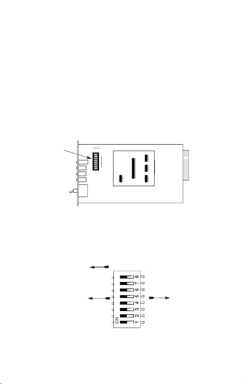
The Model 2715RC front card has a single bank of eight DIP
switches located on the top of the printed circuit board. Figure 1,
below, shows the position of the switches on the board.
Changing the DIP Switch Settings
Figure 2 shows the orientation of the DIP switches with respect to the
“ON” and “OFF” positions.
5
Figure 1. Model 2715RC board, showing DIP switch location
DIP Switch
ON OFF
8
1
Figure 2. Close up of the configuration switches
NOTE: The ON position is oriented toward the front of the Model 2715RC.
ON
OFF
Front Panel
Page 7

DIP Switches S1 - S8
The configuration switches on S1 - S8 may be set to allow configuration for a wide range of applications. Default settings of S1 through
S8 are shown in the table below. Descriptions of each switch follow
the table.
Switch SW1: Line Coding
Use Switch SW1 to control the Network Line Coding options. Set
these options to be the same as the Line Coding given to you by your
Service Provider. If you are using two Model 2715RCs together as
short range modems, set both units identically, preferably to HDB3.
SW4
Line Framing & Coding
Off HDB3
On AMI
Line Coding Options:
High Density Bipolar 3 (HDB3): In HDB3 coding, the transmitter
deliberately inserts a bipolar violation when excessive zeros in
the data stream are detected. The receiver recognizes these
special violations and decodes them as zeros. This method
enables the network to meet minimum pulse density requirements. Use HDB3 unless AMI is required in your application .
Alternate Mark Inversion (AMI): AMI coding does not inherently
account for ones density. To meet this requirement, the user
should ensure that the data inherently meets pulse density
requirements.
6
SWITCH SET SUMMARY TABLE
Position Function Factory Default Selected Option
SW1 Line Coding Off HDB3
SW2 CAS Multiframe Off Disabled
SW3 CRC-4 MF/Clock Mode Off Disabled
SW4 Clock Mode Off Network
SW5 DTE Rate Off
SW6 DTE Rate Off
SW7 DTE Rate Off
SW8 DTE Rate Off
2.048 Mbps
Clear
Channel
}
Page 8

Switch SW2: CAS Multiframe
CAS multiframe uses Timeslot 16 (TS16) to send multiframe (MF)
alignment data. In CAS MF, a multiframe is defined as 16 frames,
where a frame consists of 32 64kb/s timeslots, numbered 0 to 31.
TS16 of the first frame in the MF contains the CAS MF alignment word
in the upper four bits. The alignment word is always 0000 (binary). The
2715RC does not perform any signaling in TS16 other than to insert
the MF alignment word, in order to maintain MF alignment. When CAS
MF is disabled, the unit transmits user data in TS16; therefore, up to 31
channels are available for user data. When it is enabled, TS16 is not
available to the user. In this case, the user can use up to 30 channels
for data. CAS MF can be used with CRC-4 MF or by itself. When ennabled, both units must employ CAS MF; if one unit is set for CAS MF,
and the other is not, the one using CAS MF will detect a loss of sync.
SW2
Option
Off Disabled
On Enable
Switch SW3 & SW4: CRC-4 Multiframe/External Clock Mode
In framed mode, SW3 is used for CRC-4 MF. CRC-4 Multiframe
uses Time Slot zero to carry CRC-4 information. It operates independently of CAS MF. When CRC-4 is enabled, the unit monitors the incoming data stream for CRC-4 errors. It transmits CRC-4 error counts to
the transmitting unit. Excessive errors may cause loss of frame or loss
of sync. If CRC-4 MF is used, both units must be set for set for CRC-4
MF. Otherwise, the one using CRC-4 MF will detect loss of sync.
In unframed mode, SW3 is used along with SW4 to determine
the clock mode. In unframed mode, the model 2715RC can be set to
Network, internal, or external clock mode.
In framed mode SW4 is used alone to determine the 2715RC
transmitter timing. In framed mode, the Model 2715RC can be set to
Network or Internal Clock Mode.
The following charts represent both cases.
MULTIFRAME(G.704)
SW3 CRC-4 MF SW4 Clock Mode
On On Off Network
Off Off On Internal
Page 9

CLOCK MODES
Network Clock Transmitter timing is derived from the received line
signal.
Internal Clock Transmitter clock is derived from an internal source
clock.
External Clock Transmitter timing is derived from the local DTE
device.
Note: When using the 2715RC as a high-speed short range modem,
one unit of the link must be configured in either internal or external
clock, and the other end must be configured for network clock mode.
Switches SW5, SW6, SW7, and SW8
Use Switches SW5, SW6, SW7, and SW8 to set the DTE data rate.
SW5
SW6 SW7 SW8 Speed
Off Off Off Off Clear Channel (2.048Mbps)
1
On Off Off Off 64kbps
Off On Off Off 128kbps
On On Off Off 192kbps
Off Off On Off 256kbps
On Off On Off 384kbps
Off On On Off 512kbps
On On On Off 640kbps
Off Off Off On 768kbps
On Off Off On 1024kbps
Off On Off On 1280kbps
On On Off On 1536kbps
Off Off On On 1600kbps
On Off On On 1920kbps
Off On On On 1984kbps
2
On On On On Invalid
87
UNFRAMED (G.703)
SW3 SW4 Clock Mode
Off Off Network (Default)
Off On Internal
On On External
On Off Network
Page 10

1
NOTE: When the data rate is set to 2.048Mb/s, then the unit is in
G.703 mode, and it transmits user data on all 32 timeslots. There
is no framing information; therefore, the CAS MF (SW2) is ignored
and SW3 defaulted to clock mode. In all other rate settings, the
unit employs G.704 framing; TS0 is reserved for signaling.
2
NOTE: When not in clear channel and CAS multiframe is On
(SW2 = On), the setting for 1984 kbps is defaulted to 1920kbps.
3.2 CONFIGURING THE 1000RCM13448C REAR CARD
The Model 1000RCM13448C M/34/RJ48C Ohm rear card has two
configuration jumpers (JB3 and JB4) that may be used to connect
Signal Ground to Frame Ground on each interface (M/34 or RJ-48C).
Figure 4 (below) shows the locations of the jumpers on the 120 Ohm
rear card.
Figure 7 shows the strap location for the Model 1000RCM13448C
(M/34/RJ-48C) rear card.
9 10
Figure 7. 1000RCM13448C strap locations
JB4
JB3
123
123
Page 11

FRGND & V.35 PIN A (FRGND) (JB3)
In the connected position, this strap links Frame Ground of the
2715RC and Pin A (Frame Ground) of the V.35 connector. In the open
position, signal ground is disconnected from frame ground.
JB3
Position 1&2 = FRGND and V.35 Pin A Connected
(default)
Position 2&3 = FRGND and V.35 Pin A Not Connected
SGND & FRGND (JB4)
In the connected position, this strap links Signal Ground and frame
ground through a 100 ohm resistor. In the open position, signal ground
is disconnected from frame ground.
JB4
Position 1&2 = SGND and FRGND Connected
(default)
Position 2&3 = SGND and FRGND Not Connected
Figure 5. Orientation of Interface Card Straps
connected
open
Page 12

4.0 INSTALLATION
This section describes the functions of the Model 1001R14 rack
chassis, tells how to install front and rear Model 2715RC cards into the
chassis, and provides diagrams for wiring the interface connections
correctly.
4.1 THE MODEL 1001R14 RACK CHASSIS
The Model 1001R14 Rack Chassis (Figure 6, below) has fouteen
device card slots, plus its own power supply. Measuring only 3.5” high,
the Model 1001R14 is designed to occupy only 2U in a 19” rack.
Sturdy front handles allow the Model 1001R14 to be extracted and
transported conveniently.
4.1.1 THE RACK POWER SUPPLY
The power supply included in the Model 1001R14 rack uses the
same mid-plane architecture as the modem cards. The front card of
the power supply slides in from the front, and the rear card slides in
from the rear. They plug into one another in the middle of the rack.
The front card is then secured by thumb screws and the rear card by
conventional metal screws.
11 12
WARNING! There are no user-serviceable parts in the
power supply section of the Model 1001R14. Voltage setting changes and fuse replacement should only be performed by qualified service personnel. Contact Patton
Electronics Technical support at (301)975-1007 for more
information.
Figure 6. Model 1001R14 Rack Chassis with power supply
Page 13

The Power Supply On and Off
When plugged in, a red front panel + 12V LED will glow. Since
the Model 1001R14 is a “hot swappable” rack,
it is not necessary for
any cards to be installed before installing the power supply
.
NOTE: Please refer to the Model 1001R14 Series User Manual
AC
and DC Rack Mount Power Supplie
s for fuse and power card
replacement information.
4.2 INSTALLING THE MODEL 2715RC INTO THE CHASSIS
The Model 2715RC is comprised of a front card and a rear card.
The two cards meet inside the rack chassis and plug into each other
by way of mating 50 pin card edge connectors. Use the following
steps as a guideline for installing each Model 2715RC into the rack
chassis:
1. Slide the rear card into the back of the chassis along the
metal rails provided.
2. Secure the rear card using the metal screws provided.
3. Slide the card into the front of the chassis. It should meet the
rear card when it’s almost all the way into the chassis.
4. Push the front card
gently
into the card-edge receptacle of the
rear card. It should “click” into place.
5. Secure the front card using the thumb screws.
NOTE: Since the Model 1001R14 chassis allows “hot swapping”
of cards, it is
not necessary to power down
the rack when you
install or remove a Model 2715RC.
4.3 V.35 TERMINAL CONNECTION
The M/34 female connector of the Model 1000RCM13448C rear
card is configured as DCE (see the wiring diagram in Appendix C). To
connect to a V.35 DTE device, use a
straight-through
M/34 cable.
Page 14

4.4 CONNECTING THE NETWORK AND THE V.35 INTERFACES
Figure 4, below, shows the position of the RJ-48C network and V.35
connector on the rear of the
Model 1000RCM13448C
panel.
4.4.1 Network Interface Connection
The Network Line Interface is an eight position keyed modular jack
configured as a RJ-48C. This interface will need to be configured to
match the line parameters (i.e. framing, line coding, etc.) supplied by
the central office.
Figure 5. Model 2715RC twisted pair line interface.
Notice! Any modular twisted pair cable connected to
the rear card must be shielded cable, and the outer shield
must be properly terminated to a shielded modular plug
on both ends of the cable.
Figure 4. Model 1000RCM13448C interface card
M/34 F
RJ-45
Model
1000RCM13448C
V.35 Connector
RJ-48C Connector
1
2
3
4
5
6
7
8
Signal NameRJ-48C Jack
1
(RX) Receive (Ring)
2
(RX) Receive (Tip)
3
Shield
4
(TX) Transmit (Ring)
5
(TX) Transmit (Tip)
6
Shield
7
No connection
8
No connection
Page 15

5. 0 OP E R A T I O N
Once you have configured each Model 2715RC and connected the
cables, you are ready to operate the units. Section 5.0 describes the
power-up procedure, LED status indicators and the built-in loopback
test modes.
5.1 POWER-UP
There is no power switch on the Model 2715RC: Power is automatically applied to the Model 2715RC when its card-edge connector
makes contact with the chassis’ mid-plane socket, and when the chassis’ power supply is turned on.
Note: The Model 2715RC is a “hot
swappable” card—it will not be damaged by plugging it in or removing
it while the rack is powered up.
5.2 LED STATUS MONITORS
The Model 2715RC features four front panel LEDs that monitor
and power, data, alarm and testing conditions. Figure 8 (below) shows
the front panel location of each LED. Following Figure 8 is a description of each LED’s function.
TXD When the unit sends a one, the green TXD LED
is turned on. When it sends a zero, the yellow
TXD LED is turned on.
RXD When the unit receives a one, the green RXD
LED is turned on. When it receives a zero, the
yellow RXD LED is turned on.
1413
Figure 8. Model 2715RC front panel, showing LED indicators.
Model 2715RC
Page 16

LOS The Loss of Sync LED lights when the unit loses
synchronization with the incoming signal. This
may happen when there is a framing mismatch
or a loss of signal. In unframed mode, the LOS
LED monitors the status of the transmit clock.
ALM The alarm LED indicates the presence of a AIS
or RAI, or Out of Frame condition. The ALM LED
will blink on every half-second. Alarms may
occur due to:
•
Loss of Synchronization
• Loss of Frame
• AIS
• RAI
ERR The error LED indicates various error conditions,
including framing bit errors, excessive zeros,
controlled slips, severe errors, or bit errors (when
sending V.52 test patterns). When sending a test
pattern, the LED will remain lit if the unit does
not receive the identical pattern. When it
receives the correct pattern, the LED will turn off.
If error insertion is on, the LED will blink once a
second if everything is operating properly.
TST The test indicator LED blinks with a specific pat-
tern depending on the type of test mode. When
the unit is in local analog loop, the LED will blink
on briefly. When the unit is in remote loop, the
TST LED will blink off briefly. When the unit is
sending a test pattern or is putting the remote
unit into V.54 loopback, the TST LED will stay
on. These are the test modes:
• V.54 Loopback & V.52 Patterns
• D4 Line Loop (CO initiated)
• ESF Line Loop (CO Initiated)
• ESF Payload Loop (CO Initiated)
PWR The power indicator LED will remain lit while the
unit is powered. It turns off when the unit is not
powered.
15 16
Page 17

5.3 LOOP (V.54) DIAGNOSTICS
The Model 2715RC offers three V.54 loop diagnostics and is compatible with two Telco loop diagnostics. Use these diagnostics to test
the NTU and any communication links. These tests can be activated
via the switches on the fron panel or via signals on the serial port interface.
5.3.1 Operating Local Loopback (LL)
The Local Loopback (LL) test checks the operation of the local
Model 2715RC, and is performed separately on each unit. Any data
sent to the local Model 2715RC in this test mode will be echoed
(returned) back to the user device (i.e., characters typed on the keyboard of a terminal will appear on the terminal screen).
To perform a LL test, follow these steps:
1. Activate LL. This may be done in one of two ways:
a. Activate the “LL” signal on the DTE. If you are not sure
which lead is the “LL” signal, please refer to Appendix D.
b. Move the toggle switch on the front panel to “Local”.
2. Verify that the data terminal equipment is operating properly
and can be used for a test.
3. Perform a V.52 BER (bit error rate) test as described in
Section 5.3. If the BER test equipment indicates no faults,
but the data terminal indicates a fault, follow the manufacturer’s checkout procedures for the data terminal. Also, check
the interface cable between the terminal and the Model
2715RC.
5.3.2 Operating Remote Digital Loopback (RL)
The Remote Digital Loopback (RL) test checks the performance of
both the local and remote Model 2715RC, as well as the communication link between them. Any characters sent to the remote Model
2715RC in this test mode will be returned back to the originating device
(i.e, characters typed on the keyboard of the local terminal will appear
on the local terminal screen after having been passed to the remote
Model 2715RC and looped back).
Page 18

To perform an RDL test, follow these steps:
1. Activate RDL. This may be done in two ways:
a. Activate the “RL” signal on the DTE. If you are not sure
which lead is the “RL” signal, please refer to Appendix D.
b. Move the toggle switch on the front panel to “Remote”.
2. Perform a bit error rate test (BERT) using the internal V.52
generator (as described in Section 5.3), or using a separate
BER Tester. If the BER test indicates a fault, and the Local
Line Loopback test was successful for both converters, you
may have a problem with the twisted pair line connection.
5.4 BIT ERROR RATE (V.52) DIAGNOSTICS
The Model 2715RC offers a QRSS V.52 Bit Error Rate (BER) test
pattern. This test pattern may be invoked along with the LAL and RDL
tests to evaluate the unit(s) and the communication links.
When a QRSS test is invoked, the Model 2715RC generates a
pseudo-random bit pattern of 2
20
bits, respectively, using a mathematical polynomial. The receiving unit then decodes the received bits
using the same polynomial. If the received bits match the agreed upon
pseudo-random pattern, then the Model 2715RC and the communication link(s) are functioning properly.
To perform a V.52 test, follow these steps:
1. Activate the local loopback or remote loopback diagnostic
(See Section 5.3).
2. Locate the “PAT / PAT/E” toggle switch on the front panel of
the 2715RC and move it to the left. This activates the V.52
BER test mode and transmits a “QRSS” test pattern into the
loop. If any errors are present, the local modem’s red “ERR”
LED will blink sporadically.
3. If the above test indicates no errors are present, move the
V.52 toggle switch to the right, activating the “PAT/E” test with
errors present. If the test is working properly, the local
modem's red “ERR” LED will blink. A successful “PAT/E” test
will confirm that the link is in place, and that the Model
2715RC’s built-in “QRSS” generator and detector are working
properly.
17
Page 19

APPENDIX A
SPECIFICATIONS
Network Data Rate: 2.048 Mbps
Network Connector: RJ-48C
Nominal Impedance: 120 ohm (75 ohm available when using
Patton Model 460 Balun)
DTE Interface: V.35 (DCE Orientation) on female M/34
Line Coding: Selectable AMI or HDB3
Line Framing: G.703 (Unframed) or G.704/G.732
(Framed)
CAS Multiframing: Selectable On or Off
CRC-4 Multiframing: Selectable On or Off
Clocking: Internal, Network (Receive Recover), or
external
DTE Data Rates: 64, 128, 192, 256, 384, 512, 640, 768,
1024, 1280, 1536, 1600, 1920, 1984,
2048 kbps
Time Slot Rate: 64 kbps
DS0 Start Position: Channel 1 or Channel 0
DS0 Mapping Position: Contiguous
Diagnostics: V.54 Loopback; V.52 Patterns: QRSS
Indicators: Power, Transmit Data, Receive Data,
Alarm, Loss of Sync, Test Mode, Error
Management: 8-Position DIP Switch
Humidity: Up to 90% non-condensing
Temperature: 0 to 50
o
C
Dimensions: 12.2 x 5.3 x 1.3 cm (4.8 x 2.1 x .5 in), ⁄
lb (.11kg)
18
Data Rates Wire Gauge
(kbps) .7mm (22) .5mm (24)
2048 1.2 (.76) 1.5 (.95)
Model 2715RC Distance Table - Km (Miles)
Page 20

19
Page 21

APPENDIX C
PATTON MODEL 2715RC
INTERFACE PIN ASSIGNMENTS
M/34 Connector, Terminal Interface
Pin #
Signal
A GND (Earth Ground/Shield)
B SGND (Signal Ground)
D CTS (DCE Source)
E DSR (DCE Source, Always On)
F CD (DCE Source)
L LL (Local Loop, DTE Source)
M TM (Test Mode Indicator (DCE Source)
N RL (Remote Loop, DTE Source)
P TD (Transmit Data +, DTE Source)
R RD (Receive Data +, DCE Source)
S TD/ (Transmit Data -, DTE Source)
T RD/ (Receive Data -, DCE Source)
U SCTE (Transmit Clock+, DTE Source)
V RC (Receiver Clock +, DCE Source)
W SCTE/ (Transmit Clock-, DTE Source)
X RC/ (Receiver Clock -, DCE Source)
Y TC (Transmitter Clock +, DCE Source)
AA TC/ (Transmitter Clock -, DCE Source)
Copyright © 2006
Patton Electronics Company
All Rights Reserved
20
Page 22

Page 23

Page 24

An ISO-9001
Certified Company
Dear Valued Customer,
Thank you for purchasing Patton Electronics products! We do
appreciate your business. I trust that you find this user manual helpful.
We manufacture one of the widest selections of data communications
products in the world including CSU/DSU's, network termination units,
powered and self-powered short range modems, fiber optic modems, interface
converters, baluns, electronic data switches, data-line surge protectors,
multiplexers, transceivers, hubs, print servers and much more. We produce
these products at our Gaithersburg, MD, USA, facility, and can custom
manufacture products for your unique needs.
We would like to hear from you. Please contact us in any of the
following ways to tell us how you like this product and how we can meet your
product needs today and in the future.
Web: http://www.patton.com
Sales E-mail: sales@patton.com
Support E-mail: support@patton.com
Phone - Sales (301) 975-1000
Phone - Support (301) 975-1007
Fax: (301) 869-9293
Mail: Patton Electronics Company
7622 Rickenbacker Drive
Gaithersburg, MD 20879 USA
We are committed to a quality product at a quality price. Patton
Electronics is ISO 9001 certified. We meet and exceed the highest standards
in the industry (CE, UL, etc.).
It is our business to serve you. If you are not satisfied with any
aspect of this product or the service provided from Patton Electronics or its
distributors, please let us know.
Thank you.
Burton A.Patton
Vice President
P.S. Please tell us where you purchased this product:
_________________________________________________________
_________________________________________________________
_________________________________________________________
_________________________________________________________
_________________________________________________________
_________________________________________________________
 Loading...