

Page 1
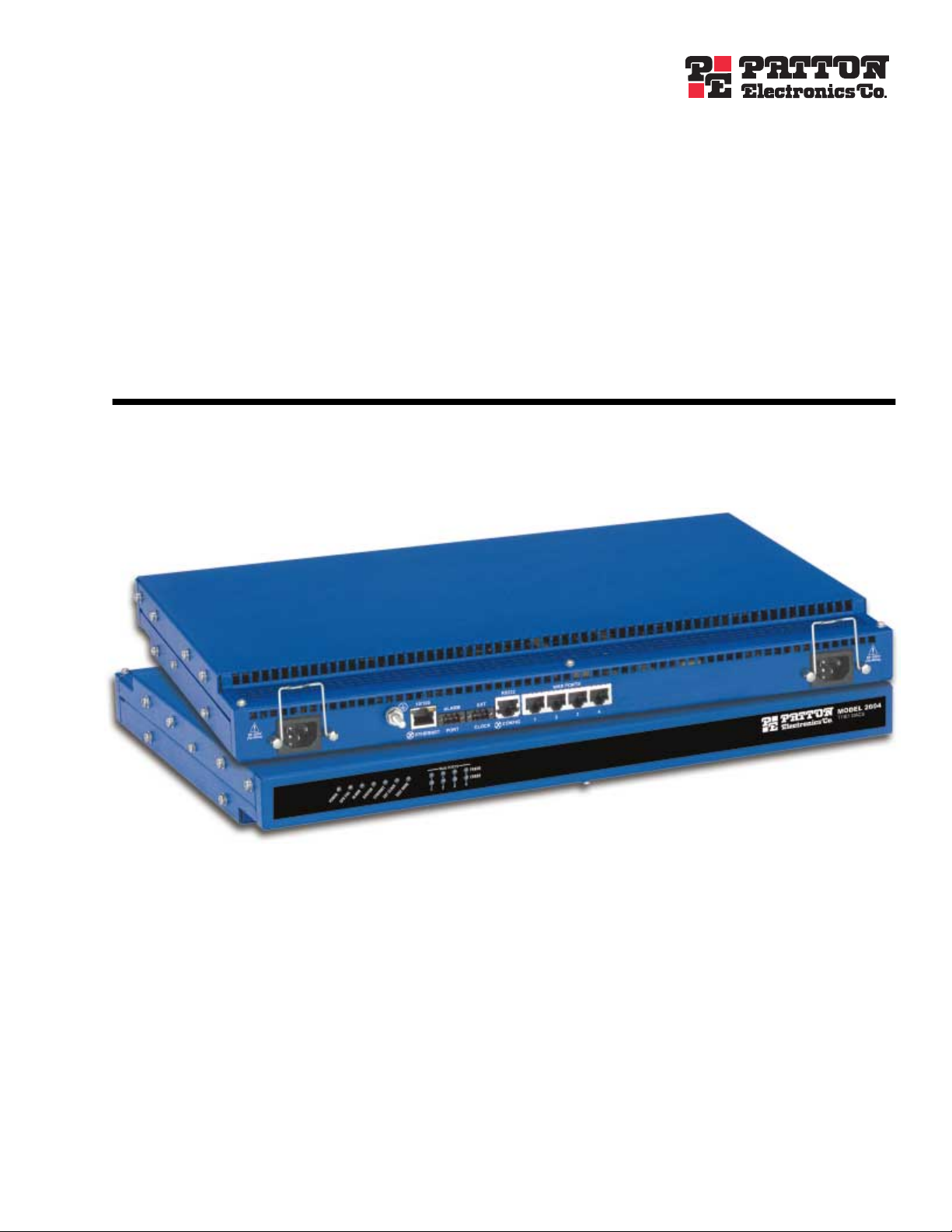
Model 2604
T1/E1 Digital Access and
Cross-Connect System (DACS)
Getting Started Guide
Sales Office: +1 (301) 975-1000
Technical Support: +1 (301) 975-1007
E-mail: support@patton.com
WWW: www.patton.com
Document Number: 110052UA Rev. A
Part Number: 07MD2604-GS-A
Revised: November 19, 2002
Page 2

Patton Electronics Company, Inc.
7622 Rickenbacker Drive
Gaithersburg, MD 20879 USA
tel: +1 (301) 975-1000
fax: +1 (301) 869-9293
support: +1 (301) 975-1007
web: www.patton.com
e-mail: support@patton.com
Copyright © 2002, Patton Electronics Company. All rights reserved.
The information in this document is subject to change without notice. Patton Electronics assumes no liability for errors that may appear in this document.
The software described in this document is furnished under a license and may be
used or copied only in accordance with the terms of such license.
Page 3

Contents
Contents ......................................................................................................................................................... 3
Compliance Information ................................................................................................................................ 7
Radio and TV Interference ...............................................................................................................................7
Industry Canada Notice ....................................................................................................................................7
FCC Information ..............................................................................................................................................7
FCC Part 68 Compliance Statement .................................................................................................................8
CE Notice .........................................................................................................................................................8
About this guide ............................................................................................................................................. 9
Audience................................................................................................................................................................. 9
Structure................................................................................................................................................................. 9
Precautions ........................................................................................................................................................... 10
Typographical conventions used in this document................................................................................................ 10
General conventions .......................................................................................................................................10
Mouse conventions .........................................................................................................................................11
1 Introduction.................................................................................................................................................. 13
T1/E1 DACS overview..........................................................................................................................................14
Hardware overview................................................................................................................................................15
WAN ..............................................................................................................................................................15
LAN ...............................................................................................................................................................16
RS-232 control port ........................................................................................................................................16
Power system ..................................................................................................................................................16
Central processing unit ...................................................................................................................................16
Alarm Port ......................................................................................................................................................16
System Timing and Clock Port .......................................................................................................................16
Temperature ...................................................................................................................................................17
Altitude ...........................................................................................................................................................17
Humidity ........................................................................................................................................................17
Physical dimensions ........................................................................................................................................18
Management services ......................................................................................................................................18
LED display ....................................................................................................................................................19
Approvals ..............................................................................................................................................................20
2 Hardware installation.................................................................................................................................... 21
Introduction..........................................................................................................................................................22
Unpacking the Model 2604 DACS .......................................................................................................................22
DACS chassis installation ......................................................................................................................................22
Cable installation...................................................................................................................................................23
Installing the power cables - AC Unit .............................................................................................................23
Installing the power cables - DC Power Supply ...............................................................................................24
Grounding the Model 2604 - AC and DC Power Supplies .............................................................................25
Connecting the Ethernet ports ........................................................................................................................26
3
Page 4

Contents
Model 2604 T1/E1 DACS Getting Started Guide
Connecting the 10/100Base-T Ethernet port to an Ethernet switch or hub ...............................................26
Connecting the 10/100Base-T Ethernet port to an Ethernet-capable workstation .....................................27
Connecting the EIA-561 RS-232 configuration port ......................................................................................27
Connecting to the T1/E1 WAN ports ............................................................................................................27
Completing the hardware installation....................................................................................................................28
3 Configuring the DACS for operation............................................................................................................ 31
Introduction..........................................................................................................................................................32
Configuration prerequisites: Preparing for the configuration .................................................................................32
Initial Configuration through the RS-232 Control Port ........................................................................................33
Connecting the DB9-RJ45 adapter with the included cable ............................................................................33
Setting up the HyperTerminal (or similar program) session ............................................................................33
Using a Web browser to complete DACS configuration........................................................................................36
Displaying the Model 2604 DACS Web Administration Pages .......................................................................37
Home page overview .................................................................................................................................38
Configuring the DS0 mapping ........................................................................................................................39
Example on configuring static connections. ...............................................................................................40
Setting the clocking source ..............................................................................................................................41
Configuring the default gateway .....................................................................................................................42
Configuring line settings and signaling for E1 .................................................................................................43
Configuring the line settings .....................................................................................................................43
Configuring line settings and signaling for T1 ................................................................................................44
Configuring the line settings .....................................................................................................................44
Saving your configuration......................................................................................................................................44
Completing the installation ...................................................................................................................................46
4 Operation and shutdown .............................................................................................................................. 49
Introduction..........................................................................................................................................................50
Activating the Model 2604....................................................................................................................................50
De-activating the Model 2604...............................................................................................................................50
5 Troubleshooting and maintenance................................................................................................................ 51
Introduction..........................................................................................................................................................52
Fault analysis .........................................................................................................................................................53
Periodic maintenance ............................................................................................................................................54
Calibration ......................................................................................................................................................54
Maintenance..........................................................................................................................................................55
Replacing the DACS .......................................................................................................................................55
Exporting the current DACS configuration ...............................................................................................55
Removing the defective DACS ..................................................................................................................56
Installing the replacement DACS ..............................................................................................................57
Verifying the hardware installation ............................................................................................................57
Importing a saved configuration ................................................................................................................57
Using the DB9-RJ45 adapter with the included cable ...............................................................................57
Setting up the HyperTerminal (or similar program) session ......................................................................58
Completing the installation .......................................................................................................................61
4
Page 5

5
Model 2604 T1/E1 DACS Getting Started Guide
Contents
6 Contacting PATTON for assistance .............................................................................................................. 63
Introduction..........................................................................................................................................................64
Contact information..............................................................................................................................................64
Warranty Service and Returned Merchandise Authorizations (RMAs)...................................................................64
Warranty coverage ..........................................................................................................................................64
Out-of-warranty service .............................................................................................................................64
Returns for credit ......................................................................................................................................64
Return for credit policy .............................................................................................................................65
RMA numbers ................................................................................................................................................65
Shipping instructions ................................................................................................................................65
Page 6

6
Contents
Model 2604 T1/E1 DACS Getting Started Guide
Page 7

Compliance Information
and TV
Radio
The DACS generates and uses radio frequency energy, and if not installed and used properly—that is, in strict
accordance with the manufacturer's instructions—may cause interference to radio and television reception.
The DACS has been tested and found to comply with the limits for a Class A computing device in accordance
with the specifications in Subpart B of Part 15 of FCC rules, which are designed to provide reasonable protection from such interference in a commercial installation. However, there is no guarantee that interference will
not occur in a particular installation. If the DACS causes interference to radio or television reception, which
can be determined by disconnecting the cables, try to correct the interference by one or more of the following
measures: moving the computing equipment away from the receiver, re-orienting the receiving antenna, and/or
plugging the receiving equipment into a different AC outlet (such that the computing equipment and receiver
are on different branches).
Industry Canada Notice
The Canadian Department of Communications label identifies certified equipment. This certification means
that the equipment meets certain telecommunications network protective, operational and safety requirements. The Department does not guarantee the equipment will operate to the user's satisfaction. Before installing this equipment, users should ensure that it is permissible to be connected to the facilities of the local
telecommunications company. The equipment must also be installed using an acceptable method of connection. In some cases, the company’s inside wiring associated with a single line individual service may be
extended by means of a certified connector assembly (telephone extension cord). The customer should be
aware that compliance with the above condition may not prevent degradation of service in some situations.
Repairs to some certified equipment should be made by an authorized maintenance facility designated by the
supplier. Any repairs or alterations made by the user to this equipment, or equipment malfunctions, may give
the telecommunications company cause to request the user to disconnect the equipment. Users should ensure
for their own protection that the ground connections of the power utility, telephone lines and internal metallic
water pipe system, are connected together. This protection may be particularly important in rural areas.
Interference
Users should not attempt to establish or modify ground connections
themselves, instead they should contact the appropriate electric
CAUTION
FCC Information
The DACS has been tested and registered in compliance with the specifications in Part 68 of the FCC rules. A
label on the equipment bears the FCC registration number. You may be requested to provide this information
to your telephone company. Your telephone company may make changes in its facilities, equipment, operations or procedures that could affect the proper operation of the DACS. If this happens, the telephone company should give you advance notice to prevent the interruption of your service. The telephone company may
decide to temporarily discontinue your service if they believe your DACS may cause harm to the telephone
network. Whenever possible, they will contact you in advance. If you elect to do so, you have the right to file a
complaint with the FCC. If you have any trouble operating the DACS, please contact Patton Electronics Technical Support at +1 301-975-1000. The telephone company may ask you to disconnect the equipment from
the telephone network until the problem has been corrected or until you are certain that the DACS is not malfunctioning. In accordance with FCC rules and regulation CFR 47 68.218(b)(6), you must notify the tele-
inspection authority or electrician.
7
Page 8

5.
4.
2.
3.
1.
Model 2604 T1/E1 DACS Getting Started Guide
phone company prior to disconnection. The following information may be required when applying to your
local telephone company for leased line facilities. The Universal Service Order Code (USOC) is RJ48. The
Facility Interface Codes (FIC) are 04DU9-BN, 04DU9-DN, 04DU9-1KN, and 04DU9-1SN. The Service
Order Code (SOC) is 6.0N.
Facility
Service
1.544 Mbps SF format without line power 04DU9-BN 6.0N RJ-48C
1.544 Mbps SF and B8ZS without line power 04DU9-DN 6.0N RJ-48C
1.544 Mbps ANSI ESF without line power 04DU9-1KN 6.0N RJ-48C
1.544 Mbps ANSI ESF and B8ZS without line power 04DU9-1SN 6.0N RJ-48C
Interface Code
Service
Code
Network
Connection
FCC Part 68 Compliance Statement
This equipment complies with Part 68 of FCC Rules. Please note the following:
You are required to request serivce from the telephone company before you connnect the DACS to a network. When you request serivce, you must provide the telephone company with the following data. When
you request T1 Service, you must provide the telephone company with the Facility Interface Code. Provide
the telephone company with both of the following codes: 04DU9-B (1.544 MB D4 framing format) and
04DU9-C (1.544 MB ESF format). The telephone company will select the code it has available. The Service Order Code(s) (SOC): 6.0N. The required Universal Service Order Code (USOC) jack: RJ 48C. The
make, model number, and FCC Registration number of the DACS.
Your telephone company may make changes to its facilities, equipment, operations, or procedures that
could affect the proper functioning of your equipment. The telephone company will notify you in advance
of such changes to give you and opportunity to maintain uninterrupted telephone service.
If your DACS causes harm to the telephone network, the telephone company may temporarily discontinue your service. If possible, they will notify you in advance, but if advance notice is not practical, you
will be notified as soon as possible and will be informed of your right to file a complaint with the FCC.
If you experience trouble with the DACS, please contact Patton Electronics, Co. for service or repairs.
Repairs should be performed only by Patton Electronics Co.
You are required to notify the telephone company when you disconnect the DACS from the network.
CE Notice
The CE symbol on your Patton Electronics equipment indicates that it is in compliance with the Electromagnetic Compatibility (EMC) directive and the Low Voltage Directive (LVD) of the European Union (EU). A
Certificate of Compliance is available by contacting Technical Support.
8
Page 9

About this guide
This guide describes installing and configuring a Patton Electronics Model 2604 T1/E1 Digital Access and
Cross-Connect System (DACS). By the time you are finished with this guide, your DACS will be connected to
uplink and downlink T1/E1s and transferring data. The instructions in this guide are based on the following
assumptions:
• The DACS will connect to a T1 or E1
• There is a LAN connected to the Ethernet port of the DACS
Audience
This guide is intended for the following users:
• Operators
• Installers
• Maintenance technicians
Structure
This guide contains the following chapters:
• Chapter 1 describes the DACS
• Chapter 2 describes installing the DACS hardware
• Chapter 3 describes configuring the DACS for use
• Chapter 4 details how to power up and deactivate the DACS
• Chapter 5 contains troubleshooting and maintenance information
• Chapter 6 contains information on contacting Patton technical support for assistance
For best results, read the contents of this guide before you install the DACS.
9
Page 10
Model 2604 T1/E1 DACS Getting Started Guide
Precautions
Notes and cautions, which have the following meanings, are used throughout this guide to help you become
aware of potential DACS problems:
Note
Calls attention to important information.
The shock hazard symbol and WARNING heading indicate a potential electric
shock hazard. Strictly follow the warning instructions to avoid injury caused
WARNING
by electric shock.
The alert symbol and WARNING heading indicate a potential safety hazard.
Strictly follow the warning instructions to avoid avoid personal injury.
WARNING
The shock hazard symbol and CAUTION heading indicate a
potential electric shock hazard. Strictly follow the instructions to
CAUTION
avoid property damage caused by electric shock.
The alert symbol and CAUTION heading indicate a potential hazard. Strictly follow the instructions to avoid property damage.
CAUTION
Typographical conventions used in this document
This section describes the typographical conventions and terms used in this guide.
General conventions
The procedures described in this manual use the following text conventions:
Table 1. General conventions
Convention Meaning
Futura bold type
Italicized Futura type
Futura type
Garamond bold type
< >
Are you ready?
% dir *.*
10
Indicates the names of menu bar options.
Indicates the names of options on pull-down menus.
Indicates the names of fields or windows.
Indicates the names of command buttons that execute an action.
Angle brackets indicate function and keyboard keys, such as <SHIFT>,
<CTRL>, <C>, and so on.
All system messages and prompts appear in the Courier font as the
system would display them.
Bold Courier font indicates where the operator must type a response or
command
Page 11
Model 2604 T1/E1 DACS Getting Started Guide
Mouse conventions
The following conventions are used when describing mouse actions:
Table 2. Mouse conventions
Convention Meaning
Left mouse button
Right mouse button This button refers the secondary or rightmost mouse button (unless you have
Point This word means to move the mouse in such a way that the tip of the pointing
Click Means to quickly press and release the left or right mouse button (as instructed in
Double-click Means to press and release the same mouse button two times quickly
Drag This word means to point the arrow and then hold down the left or right mouse but-
This button refers to the primary or leftmost mouse button (unless you have
changed the default configuration).
changed the default configuration).
arrow on the screen ends up resting at the desired location.
the procedure). Make sure you do not move the mouse pointer while clicking a
mouse button.
ton (as instructed in the procedure) as you move the mouse to a new location.
When you have moved the mouse pointer to the desired location, you can release
the mouse button.
11
Page 12

12
Model 2604 T1/E1 DACS Getting Started Guide
Page 13

Chapter 1
Chapter contents
T1/E1 DACS overview..........................................................................................................................................14
Hardware overview................................................................................................................................................15
WAN ..............................................................................................................................................................15
LAN ...............................................................................................................................................................16
RS-232 control port ........................................................................................................................................16
Power system ..................................................................................................................................................16
Central processing unit ...................................................................................................................................16
Alarm Port ......................................................................................................................................................16
System Timing and Clock Port .......................................................................................................................16
Temperature ...................................................................................................................................................17
Altitude ...........................................................................................................................................................17
Humidity ........................................................................................................................................................17
Physical dimensions ........................................................................................................................................18
Management services ......................................................................................................................................18
LED display ....................................................................................................................................................19
Approvals ..............................................................................................................................................................20
Introduction
13
Page 14
14
1 • Introduction
Model 2604 T1/E1 DACS Getting Started Guide
T1/E1 DACS overview
The Model 2604 DACS unit cross-connects DS0s from any-to-any of four E1/T1 ports with completely flexible grooming. The DACs combines dual-redundant power supplies, a time-slot multiplexer, and a centralized
management system into an ultra-sleek 1U chassis. The WAN links accept T1 or E1 network connections and
by using the built-in digital cross connect, the DACS can flexibly groom any DS0 (64 kbps) channel to any
other DS0-channel.
The entire system can be managed through SNMP/HTTP-based management screens.
Figure 1. Model 2604 DACS (
Cobalt Blue
version shown)
T1/E1 DACS overview
Page 15
15
Model 2604 T1/E1 DACS Getting Started Guide
1 • Introduction
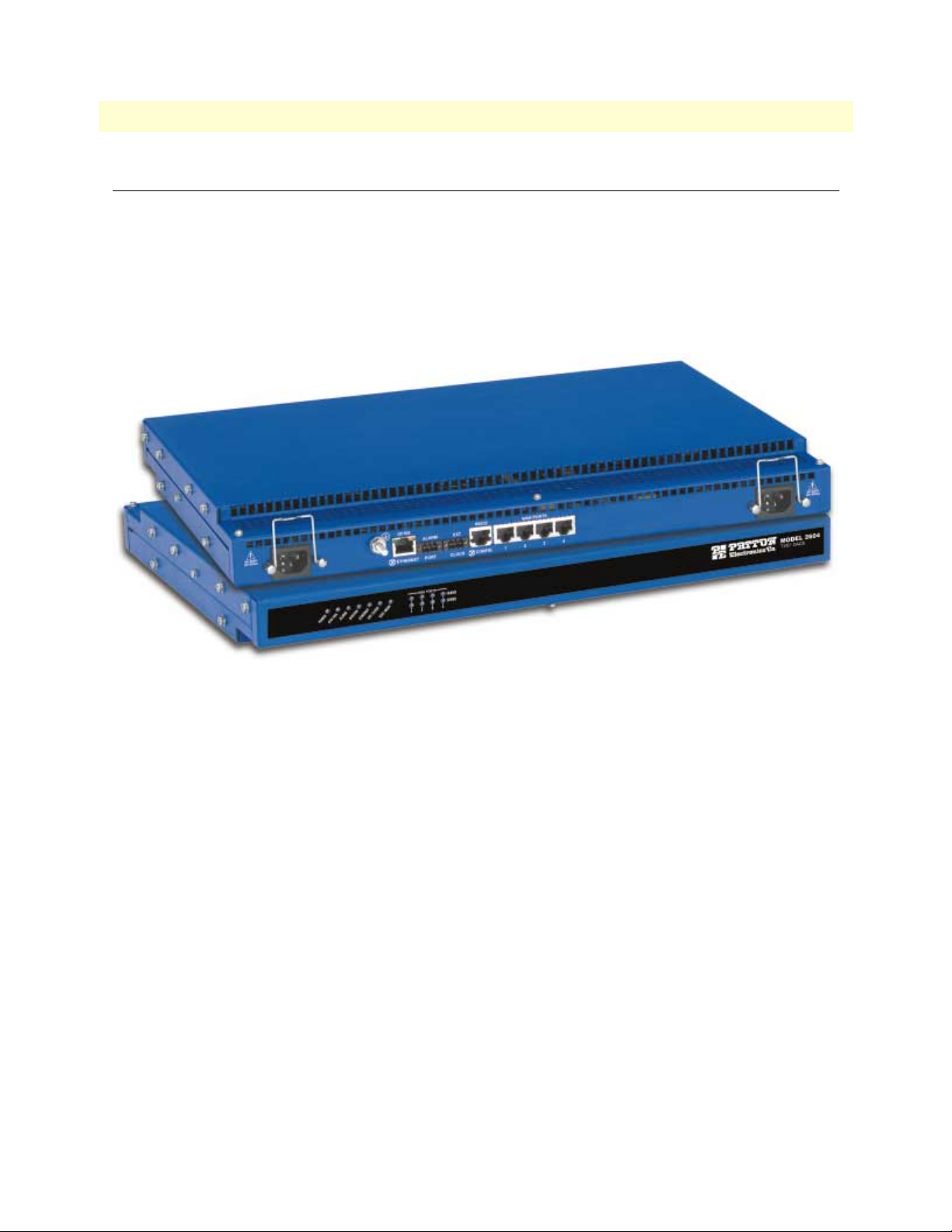
Hardware overview
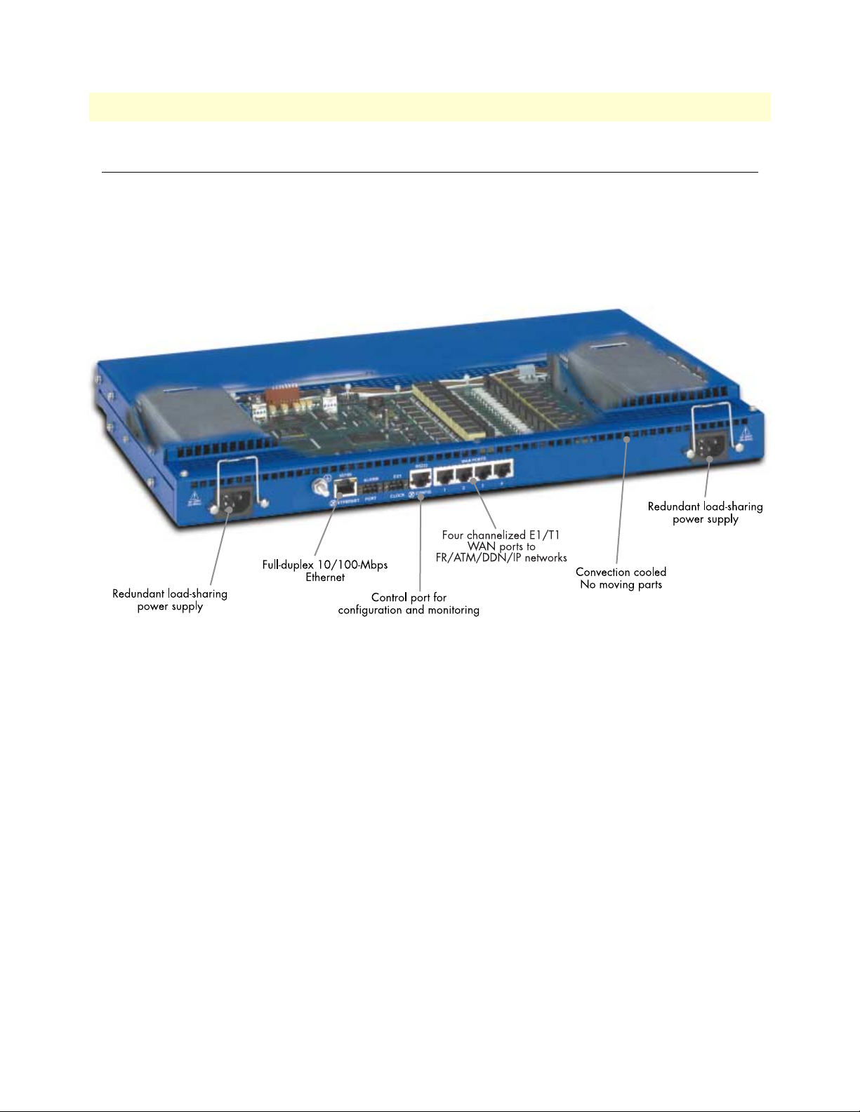
The DACS combines transmission and networking technology, concentrating four T1/E1 WAN links into a
single 1U managed chassis. The DACS (see figure 2) comprises a 1U-high 19-inch wide chassis that contains a
motherboard and two dual-redundant power supplies. A full set of LEDs are present on the chassis front panel,
while connections for WAN, LAN, alarm relay, composite clock, and control ports are present on the rear of
the chassis. Two IEC-320 receptacles provide for AC. The optional power input of -48 VDC is also available.
Figure 2. Model 2604 DACS features
WAN
The DACS includes four WAN uplink ports selectable for T1 or E1 connection to ATM/FR/DDN/IP network backbones. Also included are:
• Four built-in T1/E1 CSU/DSUs
• T1 1.544 Mbps with
- D4 or ESF framing
- AMI or B8ZS line coding
- FCC Part 68 compliant
• E1 2.048 Mbps
- framing with or without CRC4 framing
- AMI or HDB3 line coding
- CTR-12 and CTR-13 compliant
Hardware overview
Page 16

16
1 • Introduction
Model 2604 T1/E1 DACS Getting Started Guide
LAN
The 10/100-Mbps Ethernet LAN port is presented on an RJ-45 connector with an auto-sensing/full-duplex
10Base-T or 100Base-TX interface. Also included are:
• 100Base-TX half-/full-duplex operation (100 + 100)
• 10Base-T half-/full-duplex operation (10 + 10)
• Auto detection and fallback
• 10/100 Mbps link and status indicators
RS-232 control port
• The RS-232 port provides for initial configuration of the DACS. The RS-232 port supports:
• Asynchronous data rates of 19.2 kbps
• An RJ-45 connector with EIA-561 (RS-232) pinouts
• A management interface (such as HyperTerminal) that supports VT-100 terminals
• Hardware CD and DTR signals for external modems
Power system
• Internal dual-redundant, load-sharing power supplies
• Universal-input voltage range,100–240 VAC, 50/60 Hz via IEC-320 connectors
• Optional DC power supply with -40 to -72VDC via 4-way power block.
Central processing unit
The DACS employs an Intel i960VH RISC processor operating at 33 MHz/100 Mips. The CPU controls the
memory, front/back-panel and management interface for WAN time slot mapping, local switch-ing, loopback
and the management system. The memory holds:
• 4 MBytes Flash ROM
• 8 Mbytes EDO DRAM
Alarm Port
The alarm port is used to notify the operator that a pre-defined alarm has occurred. The principal features are
• User-defined alarm condition configured through the NMS
• User selectable major and minor alarms for WAN, system clock, power, and over-temperature.
• 3-contact dry relay for external alarm systems via a 3-pin terminal block connector (2A at 30 VDC)
System Timing and Clock Port
The DACS’s system timing may be derived from the composite Clock Port, an Internal Clock from an onboard chip, or a Network Clock from the T1/E1 WAN interface. The system timing is con-figured through the
NMS. The Clock Port features are:
• Input for an external 64 kbps BITS (Building Integrated Timing Supply), reference clock.
• External reference drives timing for all WAN ports.
Hardware overview
Page 17

Model 2604 T1/E1 DACS Getting Started Guide 1 • Introduction
• Selectable Master and Fallback Clock
Temperature
Operating range: 0–40°C (32–104°F)
Internal temperature: Available in real-time on the DACS Web management pages
Altitude
Maximum operating altitude: 15,000 feet (4,752 meters)
Humidity
5 to 90% relative humidity (RH), non-condensing
Hardware overview 17
Page 18
1 • Introduction Model 2604 T1/E1 DACS Getting Started Guide
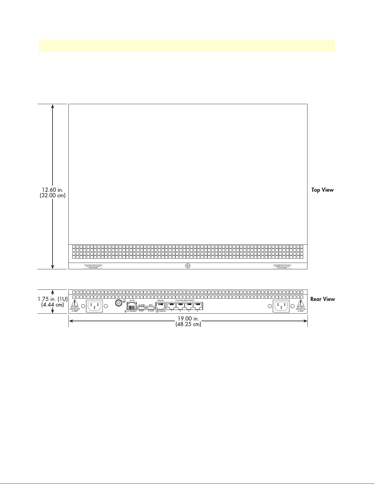
Physical dimensions
Weight: 8.94 lbs (20.12 kg)
Refer to figure 3 for height, width, and depth dimensions.
Figure 3. Model 2604 DACS chassis physical dimensions
Management services
• EIA-561 configuration port for management and control
• SNMP version 1 and 2 configuration management
• TELNET
• Ethernet
• SYSLOG Client
• Remote Software Upgrade via FTP
• Built in HTTP server for complete configuration and control using a standard Web browser
18 Hardware overview
Page 19
Model 2604 T1/E1 DACS Getting Started Guide 1 • Introduction
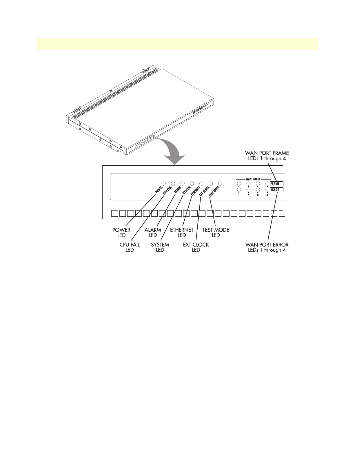
Figure 4. DACS front panel LEDs
LED display
The front panel’s LEDs (see figure 4) display the status of the four WAN ports, the Ethernet LAN port, power,
and the alarms. The front panel includes LEDs for:
• POWER: Green if power is being applied. Flashing if one power supply fails.
• CPU FAIL: Red if the CPU fails.
• ALARM: If the DACS is operating normally, the LED will be off. If a major alarm has occurred, the yellow
LED will flash; if a minor alarm condition exists, the LED will be lit constantly.
• SYSTEM: Flashes green if the DACS is operating normally.
• ETHERNET: Green if Ethernet link status is normal.
• EXT. CLOCK: Green if the DACS is being driven by the BITS clock. Off if the DACS is connected to a
(T1/E1) Network Clock or Internal Clock.
• TEST MODE: Yellow if any of the T1/E1 ports are in local switching or loop- back mode, respectively. Off
if all ports are in normal operation.
• WAN PORTS: Green indicates normal activity for each T1/E1 link. Red indicates an error on the port (for
example, loss of sync).
Hardware overview 19
Page 20

1 • Introduction Model 2604 T1/E1 DACS Getting Started Guide
Approvals
The Model 2604 DACS has achieved the following approvals:
• Safety
- IEC 60950
- UL 1950
- CSA C22.2 No. 950-95
• RTTE Directive 99/5/EC
- EMC—EN55022
- Immunity—EN55024
- Telecom—ETSI TBR 13
• EMC
- FCC Part 15 Class A
• Telecom
- FCC Part 68
- Canadian CS-03
20 Approvals
Page 21

Chapter 2 Hardware installation
Chapter contents
Introduction..........................................................................................................................................................22
Unpacking the Model 2604 DACS .......................................................................................................................22
DACS chassis installation ......................................................................................................................................22
Cable installation...................................................................................................................................................23
Installing the power cables - AC Unit .............................................................................................................23
Installing the power cables - DC Power Supply ...............................................................................................24
Grounding the Model 2604 - AC and DC Power Supplies .............................................................................25
Connecting the Ethernet ports ........................................................................................................................26
Connecting the 10/100Base-T Ethernet port to an Ethernet switch or hub ...............................................26
Connecting the 10/100Base-T Ethernet port to an Ethernet-capable workstation .....................................27
Connecting the EIA-561 RS-232 configuration port ......................................................................................27
Connecting to the T1/E1 WAN ports ............................................................................................................27
Completing the hardware installation....................................................................................................................28
21
Page 22

2 • Hardware installation Model 2604 T1/E1 DACS Getting Started Guide
Introduction
This chapter contains the following procedures for installing the Model 2604 DACS:
The AC receptacle that the DACS will be plugged into must be
located within10 feet (3 meters) of the DACS and must be easily
CAUTION
Note Before installing the DACS, you will need obtain the line type and
accessible.
encoding of the T1/E1 line from your local telephone company
(Telco).
• “Unpacking the Model 2604 DACS”—lists the contents of the DACS shipping container
• “DACS chassis installation”—describes installing the DACS on a flat surface or in a standard 19–inch rack.
• “Cable installation” on page 23—describes installing the power and network interface cables
• “Completing the hardware installation” on page 28—describes testing the DACS hardware to verify that it
is ready for software configuration.
Unpacking the Model 2604 DACS
Inspect the shipping carton for external damage. Note any damage before removing the container contents.
Report equipment damage to the shipping carrier immediately for claim purposes. Save all packing materials in
case you need to return an item to the factory for servicing.
The DACS comes with the following items:
• The MODEL 2604 Digital Cross-Connect (DACS)
• A DB-9-to-RJ-45 (EIA-561) cable and adapter (Patton Model 16F-561), 10 ft (3 m)
• Two WAN connection cables, 10 foot (3 meters) each
• Rack mounting kit with rack ears and mounting hardware
• CD-ROM containing product literature, the Getting Started Guide, and the DACS Administrator’s Refer-
ence Guide
Note Power cables are shipped separately from the Model 2604 DACS.
DACS chassis installation
Do the following:
1. If you have not done so already, remove the DACS from its shipping container.
Note The DACS should be placed as close as possible to the termination
jack provided by the Telco. Avoid installing the DACS in a location
where the power cords or network interface cables could be accidentally disconnected. The location should be well ventilated. Do not
block the DACS’s cooling vents.
22 Introduction
Page 23

Model 2604 T1/E1 DACS Getting Started Guide 2 • Hardware installation
2. If you are installing the DACS in a 19-inch rack, go to step 3. Otherwise, place the DACS at the desired
location, then go to “Cable installation” on page 23.
3. Install the rack mounting ears onto the DACS using the mounting hardware provided.
4. Place the DACS at the desired position in the rack.
5. Secure the DACS in position with the mounting screws.
Cable installation
This section describes installing the power, ground, and network interface cables.
Installing the power cables - AC Unit
This section describes installing the power cables into the IEC-320 connectors on the DACS. Do not connect
the remaining end of the power cables to the power outlet at this time. Do the following:
The AC receptacle that the DACS will be plugged into must be
located within10 feet (3 meters) of the DACS and must be easily
CAUTION
1. Install a power cable into an IEC-320 connector (see figure 5).
accessible.
Figure 5. IEC-320 connector and grounding stud locations
To avoid the risk of injury from electric shock, the power cords connected to
the IEC-320 connectors must be grounded power cords.
WARNING
Cable installation 23
Page 24

2 • Hardware installation Model 2604 T1/E1 DACS Getting Started Guide
2. Rotate the power cable retainer clip so it secures the power cable plug in the IEC-320 connector as shown
in figure 6.
Figure 6. Power cable retainer clip
3. Repeat steps 1 and 2 to install the remaining power cable.
Installing the power cables - DC Power Supply
This section describes installing the DACS for using DC power. Do not connect the remaining end of the
power cables to the DC power source. For the DC power source, the DACS is equipped with a two-position,
screw-down terminal block.
Use AWG 12 to AWG18 copper conductors only.
CAUTION
Note While looking into the DC power connector, the +DC input is on
the right and the -DC input is on the left (see figure 7).
1. Connect the earth ground of the DC source to the grounding stud on the DACS as described in the fol-
lowing section “Grounding the Model 2604 - AC and DC Power Supplies”.
2. Strip back the insulation on each of the wires approximately 1/4 inch.
3. Insert the stripped end of the positive lead into the +DC input of the terminal block. Tighten the screw
until the power lead is firmly fastened. Repeat the procedure for the negative lead, using the -DC input of
the terminal block. Make sure that all strands of the wire are captured and that there is no exposed wire.
24 Cable installation
Page 25

Model 2604 T1/E1 DACS Getting Started Guide 2 • Hardware installation
Figure 7. DC connector, - DC and + DC Input view
4. Repeat steps 1 through 3 to install the remaining DC power connection.
Grounding the Model 2604 - AC and DC Power Supplies
Do the following:
1. Assemble a ground wire using #10 AWG wire with green-colored insulation and two ring terminals. Make
the wire long enough to reach one of the following ground sources:
– The building ground rod (generally located at the site’s main service entrance)
– A sprinkler system pipe
– A cold-water pipe
– Building structural steel
To avoid the risk of personal injury, the distance between ground and the
equipment rack must not exceed the distance specified in either local electrical
WARNING
codes or the National Electrical Code.
2. Install the ground wire between the grounding stud (see figure 7) and the grounding source.
Cable installation 25
Page 26

2 • Hardware installation Model 2604 T1/E1 DACS Getting Started Guide
UNIT EQUIPP
DISCO
Connecting the Ethernet ports
The DACS has a single 10/100 Ethernet interface for connection to your LAN (see figure 8). The Ethernet
port will autosense the correct speed of the local LAN and automatically negotiate half- or full-duplex operation. This section describes connecting the DACS to the Ethernet LAN via an Ethernet hub, switch, or workstation.
Figure 8. DACS network and configuration ports
Connecting the 10/100Base-T Ethernet port to an Ethernet switch or hub
The 10/100Base-T Ethernet port (see figure 8 on page 26) is designed to connect to an Ethernet switch or
hub. Connect a straight-through CAT-5 cable (wired as shown in figure 9) between the DACS and the hub/
switch.
Figure 9. Straight-through RJ-45-to-RJ-45 Ethernet cable diagram
26 Cable installation
Page 27

Model 2604 T1/E1 DACS Getting Started Guide 2 • Hardware installation
Connecting the 10/100Base-T Ethernet port to an Ethernet-capable workstation
The 10/100Base-T Ethernet port can connect to a single Ethernet-capable workstation by means of a crossover cable. Refer to figure 10 to assemble a cross-connect cable that will connect between the NIC Ethernet
port in the workstation and the DACS 10/100Base-T Ethernet port.
Figure 10. Cross-over RJ-45-to-RJ-45 Ethernet cable diagram
Connecting the EIA-561 RS-232 configuration port
Install the supplied DB-9-to-RJ-45 cable between the DACS RS-232 port (see figure 8 on page 26) and an
open serial port on your computer. If you need to assemble your own cable, refer to the pinout diagram in
figure 11.
Figure 11. DB-9-to-RJ-45 cable diagram
Connecting to the T1/E1 WAN ports
An active T1/E1 is not necessary to configure the DACS. The factory-set default configuration of the access
server has the T1/E1 ports disabled.
Note The cable connecting the T1/E1 WAN ports to the RJ-48C termina-
tion jack should be CAT-3 or higher and extend no farther than one
mile from the digital services termination.
Cable installation 27
Page 28

2 • Hardware installation Model 2604 T1/E1 DACS Getting Started Guide
1. Refer to figure 12 for the T1/E1 RJ-48C pinout diagram.
Figure 12. T1/E1 RJ-48C pinout diagram
2. Attach the network cable from the telephone network demarc to the Primary T1/E1 port (RJ-48C) on the
DACS.
Note For 75-ohm twin-coax E1 connections, use the Patton Model 460 E1
120-ohm/75-ohm balun to convert from a 75-ohm dual-coax (from
the telco) to the 120-ohm twisted-pair interface the DACS uses.
Completing the hardware installation
This section verifies that the DACS hardware is operational to the point where you can begin configuring the
software settings. If you have an AC unit, go to step 1 in the following procedure. Otherwise, for DC units, go
to step 4.
The DACS power supply automatically adjusts to accept an input
voltage from 100 to 240 VAC (50/60 Hz, 2A).
CAUTION
1. Verify that the AC power cord included with your DACS is compatible with local standards. If it is not,
refer to Chapter 6, “Contacting PATTON for assistance” to find out how to replace it with a compatible
power cord.
2. Connect the male end of the power cord to an appropriate power outlet.
3. Verify that the green POWER LED is lit. If the POWER LED is flashing green, refer to Chapter 5, “Trou-
bleshooting and maintenance”. Otherwise, hardware installation is complete. Refer to Chapter 3, “Configuring the DACS for operation”.
CAUTION
Verify that the proper voltage is present before plugging the
power cord into the receptacle. Failure to do so could result in
equipment damage.
An approved external SELV power supply that incorporates a
disconnect device must be used and positioned within easy
reach of the operator’s position.
4. Connect the equipment to a 40–72 VDC, 1A supply source that is electrically isolated from the AC source
as stated below.
28 Completing the hardware installation
Page 29

Model 2604 T1/E1 DACS Getting Started Guide 2 • Hardware installation
– Connect the positive lead to the positive side of the DC supply.
– Connect the negative lead to the negative side of the DC supply.
The 40–72 VDC source must be reliably connected to earth.
5. Verify that the green POWER LED is lit. If the POWER LED is flashing
green, refer to Chapter 5, “Trou-
bleshooting and maintenance”.
Hardware installation is complete. Refer to Chapter 3, “Configuring the DACS for operation”.
Completing the hardware installation 29
Page 30

2 • Hardware installation Model 2604 T1/E1 DACS Getting Started Guide
30 Completing the hardware installation
Page 31

Chapter 3 Configuring the DACS for operation
Chapter contents
Introduction..........................................................................................................................................................32
Configuration prerequisites: Preparing for the configuration .................................................................................32
Initial Configuration through the RS-232 Control Port ........................................................................................33
Connecting the DB9-RJ45 adapter with the included cable ............................................................................33
Setting up the HyperTerminal (or similar program) session ............................................................................33
Using a Web browser to complete DACS configuration........................................................................................36
Displaying the Model 2604 DACS Web Administration Pages .......................................................................37
Home page overview .................................................................................................................................38
Configuring the DS0 mapping ........................................................................................................................39
Example on configuring static connections. ...............................................................................................40
Setting the clocking source ..............................................................................................................................41
Configuring the default gateway .....................................................................................................................42
Configuring line settings and signaling for E1 .................................................................................................43
Configuring the line settings .....................................................................................................................43
Configuring line settings and signaling for T1 ................................................................................................44
Configuring the line settings .....................................................................................................................44
Saving your configuration......................................................................................................................................44
Completing the installation ...................................................................................................................................46
31
Page 32

3 • Configuring the DACS for operation Model 2604 E1/T1 DACS Getting Started Guide
Introduction
This chapter contains the following procedures for configuring the Model 2604 DACS for operation:
• “Configuration prerequisites: Preparing for the configuration”—lists the items you need to have on hand
before configuring the DACS.
• “Initial Configuration through the RS-232 Control Port” on page 33—describes setting up the DACS’s
LAN IP address and netmask parameters.
• “Using a Web browser to complete DACS configuration” on page 36—describes the process to complete
the software installation parameters—that is, to bring it on line. The steps are:
- Setting Static Connections with DS0 Mapping
- Setting the System Clock Source
- IP Default Gateway
- T1/E1 WAN Links
• “Saving your configuration” on page 44—tells you how to save the configuration settings.
• “Completing the installation” on page 46—describes testing the DACS to verify that it is fully operational.
Configuration prerequisites: Preparing for the configuration
You will need the following to configure the DACS:
• A PC that includes the following:
- RS-232/V.24 serial port
- VT-100 terminal program, such as HyperTerminal
- Ethernet port
- Web browser (for example, Netscape Communicator or Microsoft Internet Explorer)
• You will need the following information to configure the DACS:
- The IP address and subnet mask for the DACS’s Ethernet port
- The IP address of the default gateway
• If you are using a T1 WAN line, you will need the following information from the telephone company
(central office):
- Line Type: either ESF or D4
- Line Coding: either B8ZS or AMI
• If you are using a E1 WAN line, you will need the following information from the Telco:
- Line Type: either E1 or E1-CRC
- Line Coding: either HDB3 or AMI
32 Introduction
Page 33

Model 2604 E1/T1 DACS Getting Started Guide 3 • Configuring the DACS for operation
Initial Configuration through the RS-232 Control Port
Initially you must configure the DACS’s IP address and—in rare instances—change the netmask from the
default settings.
Note Do not connect power or the Ethernet connection to the DACS at
this time.
Connecting the DB9-RJ45 adapter with the included cable
Do the following:
1. Connect the DB9-RJ45 adapter (Patton Model 16F-561) to your PC’s RS-232 serial port
2. Connect the RJ45-RJ45 cable between the adapter you installed in step 1 and the RS-232 Config port on
the rear of the DACS.
Setting up the HyperTerminal (or similar program) session
Do the following:
1. Open a HyperTerminal session by double-clicking on HYPERTRM.EXE.
Figure 13. Connection Description window
2. Type a connection name (for example, 2604 Config), select an icon, then click OK (see figure 13).
Initial Configuration through the RS-232 Control Port 33
Page 34

3 • Configuring the DACS for operation Model 2604 E1/T1 DACS Getting Started Guide
Figure 14. Connect To window
3. On the Connect To window (see figure 14), set Connect using: to one of the options named Direct to Com?
(where the question mark (?) refers to the number identifying the RS-232 serial port on the PC). In the
following procedure, Com1 will be the used as the port identifier.
4. Click on
OK.
5. The COM1 Properties window displays.
6. Configure your COM port settings as shown in figure 15, then click
OK.
Figure 15. COM1 Properties window
34 Initial Configuration through the RS-232 Control Port
Page 35

Model 2604 E1/T1 DACS Getting Started Guide 3 • Configuring the DACS for operation
7. Click on the File menu, then select
Properties
.
8. Configure the settings for Function, arrow and ctrl keys act as to Terminal keys as shown in figure 16.
Figure 16. Terminal keys configuration
9. Connect the male end of the Model 2604 DACS’ power cables to the power outlets.
10. On your HyperTerminal connection window, boot up information will display, eventually followed by a
login request window resembling that shown in figure 17.
Figure 17. Login window
11. For the user name, type superuser.
Initial Configuration through the RS-232 Control Port 35
Page 36

3 • Configuring the DACS for operation Model 2604 E1/T1 DACS Getting Started Guide
12. For the password, type superuser; the TOP LEVEL MANAGEMENT window then appears (see
figure 18).
Figure 18. VT-100 Top Level Management window
13. Type k for System, then press <Enter>.
14. Under System, type 1 for Details, then press
15. Enter g for LAN Address, then press
<Enter>.
16. Type your LAN IP address followed by pressing
<Enter>.
<Enter>.
17. Press the left-arrow cursor key on your keyboard to return to the previous screen.
18. If you do not need to change the LAN Mask from the default of 255.255.255.0, go to step 21. Otherwise,
press h and type the new LAN Mask in the same manner as when entering a LAN IP address.
19. Press the left-arrow cursor key until the TOP LEVEL MANAGEMENT window displays.
20. Select a for Home, then press
<Enter>.
21. Under the Current Status page, type 1 (store Config(1)) to save the changes you have just made to the
configuration.
This completes the initial configuration of the DACS. The next steps in configuration will be done directly
through Ethernet via your Web browser.
Using a Web browser to complete DACS configuration
This section describes configuring the following:
• Displaying the DACS home page (see “Displaying the Model 2604 DACS Web Administration Pages” on
page 37)
• Setting static connections with DS0 mapping (see “Configuring the DS0 mapping” on page 39)
36 Using a Web browser to complete DACS configuration
Page 37

Model 2604 E1/T1 DACS Getting Started Guide 3 • Configuring the DACS for operation
• Setting the clocking source (see “Setting the clocking source” on page 41)
• Configuring the IP default gateway (see “Configuring the default gateway” on page 42)
• Configuring the T1/E1 WAN links (see “Configuring line settings and signaling for E1” on page 43
or“Configuring line settings and signaling for T1” on page 44)
Displaying the Model 2604 DACS Web Administration Pages
Do the following:
1. Connect your PCs Ethernet connection to the Ethernet.
2. Connect the DACS’s DACS 10/100 Ethernet connection to the Ethernet LAN.
3. Start a Web browser session. In the portion of the browser window where the URL is displayed, type the IP
address of the DACS (for example, if the DACS IP address 123.124.221.10, you would type
123.124.221.10 in the browser’s URL area). If you do not have an IP address in your DACS, refer to
“Initial Configuration through the RS-232 Control Port” on page 33.
4. When prompted for a username, type superuser, then press
password, then press
<Enter>.
5. The DACS home page displays (see figure 19).
Figure 19. Home page
<Enter>. Next type superuser as the
Using a Web browser to complete DACS configuration 37
Page 38

3 • Configuring the DACS for operation Model 2604 E1/T1 DACS Getting Started Guide
Home page overview
The HOME window is divided into two panes: the Configuration Menu pane and the configuration/information
pane (see figure 20). The
Configuration Menu contains the links to the various DACS subsystems, while the
configuration/information pane is where you can view status and other information, or make changes to the
system configuration. Unlike the Configuration Menu pane, which looks the same no matter which subsystem
page you may move to, the configuration/information pane contents will change as you move from one subsystem page to another.
Figure 20. HOME page window panes
38 Using a Web browser to complete DACS configuration
Page 39

Model 2604 E1/T1 DACS Getting Started Guide 3 • Configuring the DACS for operation
Figure 21. Immediate Actions buttons
From the Home page, the following actions can be performed:
• Record Current Configuration—clicking on this button (see figure 21) saves the current configuration in
volatile DRAM memory to FLASH memory. Once the configuration is saved into FLASH memory, the
configuration will not be lost even if the power is cycled on the DACS. Initially, any changes made to the
DACS configuration are stored in volatile RAM first, enabling the user to set the box up with a working
configuration before committing it to storage in FLASH. The configuration changes become permanent
when you select Record Current Configuration.
Note If you want to save the configuration changes that you have made,
you must click on
Record Current Configuration, otherwise all con-
figuration changes will be lost if the power to the DACS is turned off.
• Hard Reset—this button (see figure 21) causes the DACS to perform a cold restart. When you select Hard
Reset, the DACS confirms that you want to execute this command. Then, the DACS will disconnect all
current sessions, re-initialize the interfaces, and re-load configuration parameters from FLASH.
• Set Factory Default Configuration—this button (see figure 21) clears out the configuration in FLASH and
loads the factory default parameters into FLASH memory. The factory default settings will not execute on
the DACS until it is re-booted by doing a Hard Reset.
Note Set Factory Default Configuration (figure 21) will delete any routing
information, the DACS’s Ethernet IP address, and any other site-specific settings made for your particular installation. You will have to reenter the DACS’s Ethernet IP address and netmask using the rear
panel control port before using the HTTP/HTML
Management pages.
Configuring the DS0 mapping
Do the following to set the DS0 Mapping of the modems:
1. Click on
DS0 Mapping on the Configuration Menu.
Using a Web browser to complete DACS configuration 39
Page 40

3 • Configuring the DACS for operation Model 2604 E1/T1 DACS Getting Started Guide
2. Set the
DS0 Display Type
(see figure 22) to
displayLongForm(0)
. To create each static connection (which
is the DS0 Mapping Process), you will select from the following parameters:
Device Type. This setting specifies the physical interface onto which you will be connecting. Within the
–
DACS, the user has the option of selecting T1/E1 WAN line.
Figure 22. DS0 Mapping Configuration window
– Device Slots. This parameter identifies which DS0 channels—each DS0 channel is 64 kbps—that you
would like to connect. Each time slot in a T1 or E1 WAN port has 24 or 31 DS0 channels, respectively.
When selecting the slots you must select the same number of slots on the "A" and "B" side of the connection. The slots are selected by entering a string that represents the slots. For a WAN port configured
as a T1, the available slots are numbered from 1–24. For a WAN port configured as an E1, the available
slots are 1–31. The following notation should be used for entering the slots.
• dash: (-) 1 - 4
• comma: (,) 1,4,9
• combo: 1 - 2, 3, 6 - 7
• “A” and “B” identify the two ends of the static connection.
Example on configuring static connections.
Connect a T1 line, (WAN) Port 2, timeslots 4 – 5 and 7, to another T1 line, (WAN) Port 3, timeslots 8 – 10.
Solution: Complete the following steps.
1. Under “Dev Type A,” select t1-e1(1)
2. Under “Dev Num A,” select port2(2)
3. Under “Dev Slots A,” enter 4-5,7
4. Under “Dev Type B,” select t1-e1(1)
5. Under “Dev Num B,” select port3(3)
6. Under “Dev Slots B,” enter 8-10
7. Click on “Submit Query” to the right of the static connection entry which you just completed.
40 Using a Web browser to complete DACS configuration
Page 41

Model 2604 E1/T1 DACS Getting Started Guide 3 • Configuring the DACS for operation
8. Click on the T1/E1 Assignment subsystem in the DACS Configuration Menu. You will see the appropri-
ate three time slots statically mapped between WAN port 2 and WAN port 3.
Setting the clocking source
This section configures the Main Reference and Fallback Reference Clock for the Model 2604 DACS. You can
choose any of the WAN ports, an internal oscillator or an externally provided clock for the system clock in the
DACS. The Main Reference provides the DACS’s system clock unless it fails or is disconnected. Should this
occur, the Fallback Reference will be the clocking source for the DACS’s system clock.
Do the following to set the clocking source:
1. Click on Clocking on the Configuration Menu.
2. Connect your T1/E1 WAN connection to WAN Port #1 on the rear panel of the DACS. Assuming this is
the WAN link you wish to use as the Main Reference, set
Main Reference to
wan-1(1)
(see figure 23).
Figure 23. System Clocking Configuration window
3. Set the Fallback Reference to none(0) if you have no other T1/E1 WAN links for connection to the
DACS. Otherwise, select the appropriate WAN port under Fallback Reference.
4. Click on
Submit Query.
Using a Web browser to complete DACS configuration 41
Page 42

3 • Configuring the DACS for operation Model 2604 E1/T1 DACS Getting Started Guide
Configuring the default gateway
Do the following to add the default gateway:
1. Select
IP on the Configuration Menu, then click on Routing Info…(see figure 24).
Figure 24. IP Routing Information window
2. The route which you already see in the table appeared upon the configuration of the LAN IP address.
3. To enter the default gateway, use the first Add Route line. The Destination shall remain as 0.0.0.0. There is
no mask to enter.
4. Enter the IP address in the Gateway box. This is the default gateway.
5. Click on the
Add Route button.
42 Using a Web browser to complete DACS configuration
Page 43

Model 2604 E1/T1 DACS Getting Started Guide 3 • Configuring the DACS for operation
Figure 25. T1/E1 Link Activity window
Configuring line settings and signaling for E1
1. Select T1/E1 Link on the Configuration Menu. The T1/E1 Link Activity window appears (see figure 25).
Link: 1 corresponds to Line 1 on the DACS. Under Link 1, Click on Configuration then Modify. The Line
2.
Interface Settings section of the WAN Circuit Configuration window appears (see figure 26).
Figure 26. WAN Circuit Configuration window, Line Interface Settings section
Configuring the line settings
1. Click on the Line Type pop-up menu (see figure 26 on page 43) and choose either dsx1EX(4) or dsx1E1-
CRC(5).
2. Click on the
Line Coding pop-up menu (see figure 26 on page 43) and choose either dsx1AMI(5) or
dsxHDB3(3). Most installations will use HDB3.
Using a Web browser to complete DACS configuration 43
Page 44

3 • Configuring the DACS for operation Model 2604 E1/T1 DACS Getting Started Guide
3. Click on the Line Build Out pop-up menu (see figure 26 on page 43) and select e1pulse(1).
4. Click on
Submit Query.
At this point, the WAN front panel LEDs will become active. A solid green FRAME light indicator means that
the DACS has sychronized with the E1 line. If the E1 line is not connected to the DACS, you will see Alarms
on that WAN port. These should disappear upon connecting the E1 line to the WAN port on the rear of the
DACS.
Configuring line settings and signaling for T1
1. Select T1/E1 Link on the Configuration Menu. The T1/E1 Link Activity window appears (see figure 25 on
page 43).
Link: 1 corresponds to Line 1 on the DACS. Under Link 1, Click on Configuration then Modify. The Line
2.
Interface Settings section of the WAN Circuit Configuration window appears (see figure 26 on page 43).
Configuring the line settings
1. Click on the Line Type pop-up menu (see figure 26 on page 43) and choose from the following options:
– dsx1ESF Extended SuperFrame DS1
– dsx1D4 AT&T D4 format DS1
2. Click on the
Line Coding pop-up menu (see figure 26 on page 43). The most common options are:
dsx1B8ZS and dsx1AMI.
3. Click on the
Line Build Out pop-up menu (see figure 26 on page 43) and select t1pulse0dB(1).
4. Click on
Submit Query.
At this point, the WAN front panel LEDs will become active. A solid green FRAME light indicator means that
the DACS has sychronized with the T1 line. If the T1 line is not connected to the DACS, you will see Alarms
on that WAN port. These should disappear upon connecting the T1 line to the WAN port on the rear of the
DACS.
Saving your configuration
The basic configuration for the DACS is now finished. Do the following to save your configuration settings:
1. Select
2. Click on the
3. The Import/Export function enables you to make a backup (or export) copy of your access server’s configu-
Home on the Configuration Menu. The Home window appears (see figure 19 on page 37).
Record Current Configuration button (see figure 21 on page 39).
Note Failing to click on the Record Current Configuration button before
you power down or reset the DACS will cause your changes to be
lost.
ration parameters. By exporting the configurations, the saved files can quickly be loaded (or imported) into
a replacment access server—greatly speeding up the installation process should an access server need
replacing.
Note All actions for Import/Export require superuser access privileges.
44 Saving your configuration
Page 45

Model 2604 E1/T1 DACS Getting Started Guide 3 • Configuring the DACS for operation
4. To import or export a configuration, click on Import/Export under the Configuration Menu to display the
Import/Export main window (see figure 27).
Figure 27. Import/Export main window
5. To export the flash configuration, click on the Export Flash link on the Import/Export main page. The
access server will display text configuration information resembling that shown in figure 28.
Figure 28. Typical access server flash memory configuration data
Saving your configuration 45
Page 46

3 • Configuring the DACS for operation Model 2604 E1/T1 DACS Getting Started Guide
To save the displayed data as a text file, select the Save option on your browser (see figure 29). For example,
under Netscape, select
parameters to a text file. Select the location where you want the file stored, type a file name, and click
File > Save As. A dialog box will display enabling you to save the contents of the export
Save.
Figure 29. Saving the access server flash memory configuration data as a text file
Completing the installation
This section verifies that the DACS is fully operational.
1. Temporarily disconnect the male ends of both power cords from the power outlet. Wait 30 seconds, then
plug the power cords in again.
2. Verify that the green POWER LED is lit. If the POWER LED is flashing green, refer to Chapter 5, “Trou-
bleshooting and maintenance”.
3. Verify that the Link 1 Frame LED illuminates, indicating that the DACS is synchronizing with the T1/E1
signal.
4. Verify that after 5 seconds, the Link A Error LED begins flashing, indicating that the DACS is satisfied
with the quality of the T1/E1 signal.
5. Verify that after 10 seconds, the Link A Error LED extinguishes, indicating that the DACS is satisfied with
the network signal and that the link is ready for use.
46 Completing the installation
Page 47

Model 2604 E1/T1 DACS Getting Started Guide 3 • Configuring the DACS for operation
Note If the DACS does not respond as described, the most likely cause is
that the DACS default settings are not compatible with the T1/E1
line. If this is the case, use the RS-232 CONFIG port to correct the
DACS settings. You will have to examine the T1/E1 Link section in
the configuration pages in the DACS.
6. There are two LEDs on the DACS 10/100 Ethernet port: a green LED that indicates link status and activ-
ity, and a yellow LED that indicates line speed.
Verify that the green LED is either flashing green (meaning that packets are being received at the Ethernet
port) or solid green (meaning that the link is valid but no packets are being received).
Congratulations! Your DACS is now installed. For more in-depth information about configuring your DACS
settings, refer to the DACS Administrator’s Reference Guide included on your DACS CD-ROM. Otherwise,
refer to Chapter 4, “Operation and shutdown” for information on activating and de-activating your Model
2604 DACS.
Completing the installation 47
Page 48

3 • Configuring the DACS for operation Model 2604 E1/T1 DACS Getting Started Guide
48 Completing the installation
Page 49

Chapter 4 Operation and shutdown
Chapter contents
Introduction..........................................................................................................................................................50
Activating the Model 2604....................................................................................................................................50
De-activating the Model 2604...............................................................................................................................50
49
Page 50

4 • Operation and shutdown Model 2604 T1/E1 DACS Getting Started Guide
Introduction
This chapter describes how to start or power-down the DACS.
Activating the Model 2604
Once the DACS has been installed, no operator action is required under normal conditions; the DACS is
designed for unattended operation. The DACS does not have a power switch and powers up immediately upon
connecting the power cords to the DACS. When either power supply is connected to power, the DACS will
immediately begin its boot-up cycle. However, both power supplies must be connected to power for the redundancy feature to work.
When power is applied to the DACS the following should occur:
1. The POWER LED illuminates.
2. The Link 1 Frame LED illuminates, indicating that the DACS is synchronizing with the T1/E1 signal.
3. After 5 seconds, the Link A Error LED flashes, indicating that the DACS is satisfied with the quality of the
T1/E1 signal.
4. After 10 seconds, the Link A Error LED extinguishes, indicating that the DACS is satisfied with the net-
work signal and that the link is ready for use.
5. There are two LEDs on the DACS 10/100 Ethernet port: a green LED that indicates link status and activ-
ity, and a yellow LED that indicates line speed.
The green LED is either flashing green (meaning that packets are being received at the Ethernet port) or
solid green (meaning that the link is valid but no packets are being received).
The yellow LED is either lit (indicating 100-Mbps operation) or off (indicating 10-Mbps operation).
Note The yellow LED reflects the speed of the last valid Ethernet
connection.
The Model 2604 DACS is operational.
De-activating the Model 2604
Perform the following procedure to deactivate the DACS.
1. Disconnect the male ends of both power cords from the power distribution strip or to a wall outlet.
2. Verify that the POWER LED extinguishes.
50 Introduction
Page 51

Chapter 5 Troubleshooting and maintenance
Chapter contents
Introduction..........................................................................................................................................................52
Fault analysis .........................................................................................................................................................53
Periodic maintenance ............................................................................................................................................54
Calibration ......................................................................................................................................................54
Maintenance..........................................................................................................................................................55
Replacing the DACS .......................................................................................................................................55
Exporting the current DACS configuration ...............................................................................................55
Removing the defective DACS ..................................................................................................................56
Installing the replacement DACS ..............................................................................................................57
Verifying the hardware installation ............................................................................................................57
Importing a saved configuration ................................................................................................................57
Using the DB9-RJ45 adapter with the included cable ...............................................................................57
Setting up the HyperTerminal (or similar program) session ......................................................................58
Completing the installation .......................................................................................................................61
51
Page 52

5 • Troubleshooting and maintenance Model 2604 T1/E1 DACS Getting Started Guide
Introduction
This chapter describes troubleshooting and fault analysis that can be performed by the operator. If you require
more help, refer to Chapter 6, “Contacting PATTON for assistance”. Refer to table 3 for a list of common
symptoms and suggested remedies.
Note The following information assumes that there is only one failure
involving the DACS and that if you perform the corrective action
listed, it will solve the problem. If you are unable to correct a failure,
refer to Chapter 6, “Contacting PATTON for assistance”.
Table 3. Symptoms
Problem Corrective Action
POWER
POWER LED is flashing Either one of the external power sources or one of the 2064’s power sup-
CPU FAIL
ALARM
SYSTEM
ETHERNET green LED is extinguished
LED is extinguished Verify that power is being supplied to the DACS.
plies has malfunctioned. The DACS will function normally indefinitely
with one power supply. To verify the suspected problem, contact Patton
Technical Support to determine whether the DACS needs to be replaced
or not.
LED is lit CPU is unable to load the software from FLASH to RAM for operation. As
soon as possible, unplug both power cables from the DACS, wait 30 seconds, then plug the cables back into the DACS to see if the problem disappears. If the
power-up cycle, contact Patton Technical Support to determine whether
the DACS needs to be replaced or not.
LED is lit Indicates that an alarm condition has been detected.
LED is not flashing The DACS is not functioning properly. As soon as possible, unplug both
power cables from the DACS, wait 30 seconds, then plug the cables
back into the DACS to see if the problem disappears. If the
is still lit after the DACS completes the power-up cycle, contact Patton
Technical Support to determine whether the DACS needs to be replaced
or not.
CPU FAIL
LED remains lit after the DACS completes the
SYSTEM
LED
• A valid link has not been detected. Verify that the cable is plugged
into the hub, switch, or workstation and the DACS.
• Verify that the hub, switch, or workstation is powered on.
• Verify that the correct cable is being used. Depending on whether you
are connecting to a workstation (PC), hub, or switch, either a straightthrough or cross-over cable.
• Replace the cable. If the problem still exists, contact Patton Technical
Support to determine whether the DACS needs to be replaced or not
52 Introduction
Page 53

Model 2604 T1/E1 DACS Getting Started Guide 5 • Troubleshooting and maintenance
Fault analysis
The following procedures outline steps you should follow when troubleshooting a DACS malfunction.
1. If possible, talk to the person who filed the trouble complaint and determine the operational symptoms.
Record the symptoms on the appropriate trouble report form (include the front panel LED indications).
2. Refer to table 4 for LED definitions and compare the recorded results from the trouble report against those
in the table, then refer to the section recommended in the table for the maintenance procedure that will
repair the malfunction.
Table 4. LED definitions
LED Location Color Status Meaning
POWER Front panel Green On solid Power is being applied. No action recommended.
Flashing Either one of the external power sources or one of the 2064’s
power supplies has malfunctioned. The DACS will function normally indefinitely with one power supply. To verify the suspected
problem, contact Patton Technical Support to determine whether
the DACS needs to be replaced or not.
Off No input power is being applied. Verify that power is being
supplied to the DACS.
CPU FAIL Front panel Red On solid CPU is unable to load the software from FLASH to RAM for
operation. As soon as possible, unplug both power cables from
the DACS, wait 30 seconds, then plug the cables back into the
DACS to see if the problem disappears. If the
remains lit after the DACS completes the power-up cycle, contact Patton Technical Support to determine whether the DACS
needs to be replaced or not.
Off The CPU is operating normally. No action recommended.
ALARM Front panel Red On solid A minor alarm condition has been detected.
Flashing A major alarm condition has been detected.
Off The DACS is operating normally. No action recommended.
SYSTEM Front panel Green
Flashing The DACS is operating normally. No action recommended.
Off The DACS is not functioning properly. As soon as possible,
unplug both power cables from the DACS, wait 30 seconds,
then plug the cables back into the DACS to see if the problem
disappears. If the
pletes the power-up cycle, contact Patton Technical Support to
determine whether the DACS needs to be replaced or not.
SYSTEM
LED is still lit after the DACS com-
CPU FAIL
LED
Fault analysis 53
Page 54

5 • Troubleshooting and maintenance Model 2604 T1/E1 DACS Getting Started Guide
Table 4. LED definitions (Continued)
LED Location Color Status Meaning
ETHERNET Front panel Green On solid Link status is nominal for the Ethernet port. No action recom-
mended.
Off
• A valid link has not been detected. Verify that the cable is
plugged into the hub, switch, or workstation and the DACS.
• Verify that the hub, switch, or workstation is powered on.
• Verify that the correct cable is being used. Depending on
whether you are connecting to a workstation (PC), hub, or
switch, either a straight-through or cross-over cable.
• Replace the cable. If the problem still exists, contact Patton
Technical Support to determine whether the DACS needs to
be replaced or not
Ext. Clock Front panel Green
WAN PORT— FRAME Front panel Green On solid Indicates normal activity at each of the four T1/E1/PRI links. No
WAN PORT— ERROR Front panel Red On solid Indicates normal activity at each of the four T1/E1/PRI links. No
10/100 ETHERNET Rear panel Green On solid Link is valid. No action recommended.
On solid An external clock source is being used.
action recommended.
Flashing Indicates that the DACS is detecting the network, but is unable
to synchronize with it.
Off Indicates an error.
action recommended.
Off Indicates an error.
Off
• A valid link has not been detected. Verify that the cable is
plugged into the hub, switch, or workstation and the DACS.
• Verify that the hub, switch, or workstation is powered on.
• Verify that the correct cable is being used. Depending on
whether you are connecting to a workstation (PC), hub, or
switch, either a straight-through or cross-over cable.
• Replace the cable. If the problem still exists, contact Patton
Technical Support to determine whether the DACS needs to
be replaced or not.
Flashing Packets are detected at the Ethernet port. No action recom-
mended.
10/100 ETHERNET Rear panel Yellow On solid 100 Mbps speed. No action recommended.
Off 10 Mbps speed. No action recommended.
Periodic maintenance
Other than using a lint-free cloth to clean dust off the DACS chassis, the DACS requires no periodic maintenance.
Calibration
The DACS requires no calibration.
54 Periodic maintenance
Page 55

Model 2604 T1/E1 DACS Getting Started Guide 5 • Troubleshooting and maintenance
Maintenance
This section describes replacing the DACS.
Replacing the DACS
If you isolate a problem to the a DACS component, the entire DACS must be replaced as follows:
Exporting the current DACS configuration
The Import/Export function enables you to make a backup (or export) copy of your access server’s configuration parameters. By exporting the configurations, the saved files can quickly be loaded (or imported) into a
replacment access server—greatly speeding up the installation process should an access server need replacing.
1. If you already have a recently exported backup of your configuration, go to “Removing the defective
DACS” on page 56.
2. To export a configuration, connect your Web browser to the Administration Pages, then click on Import/
Export under the Configuration Menu to display the Import/Export main window (see figure 30).
Figure 30. Import/Export main window
Note The parameters that will be exported are the power-up settings as
they are stored in flash memory and may not be the current operating
parameters. To ensure that you export the most current parameters,
go to
HOME, then click on the Record Current Configuration button
under
Immediate Actions.
3. To export the flash configuration, click on the
Export Flash link on the Import/Export main page. The
access server will display text configuration information resembling that shown in figure 31.
Maintenance 55
Page 56

5 • Troubleshooting and maintenance Model 2604 T1/E1 DACS Getting Started Guide
Figure 31. Typical access server flash memory configuration data
4. To save the displayed data as a text file, select the Save option on your browser (see figure 32). For exam-
ple, under Netscape, select
File > Save As. A dialog box will display enabling you to save the contents of
the export parameters to a text file. Select the location where you want the file stored, type a file name, and
click
Save.
Figure 32. Saving the access server flash memory configuration data as a text file
Removing the defective DACS
1. Remove the replacement DACS from its shipping container and place it near where the malfunctioning
DACS is located.
56 Maintenance
Page 57

Model 2604 T1/E1 DACS Getting Started Guide 5 • Troubleshooting and maintenance
2. Unplug both male power cable connectors from their outlets.
3. Rotate the power cord retainer clips out of the way, then remove both power cables from the malfunction-
ing DACS.
4. Disconnect and label the following cables from the malfunctioning DACS:
– the T1/E1 WAN cables
– the RS-232 CONFIG cable
– the 10/100 ETHERNET cable
5. Disconnect the ground wire from the grounding stud.
6. If the DACS is mounted in a rack, remove it from the rack.
7. Place the malfunctioning DACS in the container that the replacement DACS came in so you can return
the DACS for repair.
Installing the replacement DACS
1. If you are installing the replacement DACS in a 19-inch rack, go to step 2. Otherwise, place the DACS at
the desired location, then go to step 5.
2. Install the rack mounting ears onto the DACS using the mounting hardware provided.
3. Place the DACS at the desired position in the rack.
4. Secure the DACS in position with the mounting screws.
5. Install the ground wire onto the grounding stud.
6. Connect the following cables onto the DACS:
– the T1/E1 WAN cables
– the RS-232 CONFIG cable
– the 10/100 ETHERNET cable
7. Install the power cable into their IEC-320 connectors.
8. Rotate the power cable retainer clips so they secure the power cable plugs in the IEC-320 connectors.
Verifying the hardware installation
1. Connect the male end of the power cord to a power distribution strip or to a wall outlet.
2. Verify that the green POWER LED is lit.
Importing a saved configuration
Before the DACS can be configured, the IP address and the netmask needs to be set up. This setup is done
through the DACS RS-232 CONFIG port on the DACS.
Using the DB9-RJ45 adapter with the included cable
Do the following:
1. Connect the DB9-RJ45 adapter to your PC’s RS-232 serial port
Maintenance 57
Page 58

5 • Troubleshooting and maintenance Model 2604 T1/E1 DACS Getting Started Guide
2. Connect the RJ45-RJ45 cable between the adapter you installed in step 1 and the RS-232 Config port on
the rear of the DACS.
Setting up the HyperTerminal (or similar program) session
Do the following:
1. Open a HyperTerminal session by double-clicking on HYPERTRM.EXE.
Figure 33. Connection Description window
2. Type a connection name (for example, DACS Config), select an icon, thenclick OK (see figure 33).
Figure 34. Connect To window
3. On the Connect To window (see figure 34), set Connect using: to one of the options named Direct to Com?
(where the question mark (?) refers to the number identifying the RS-232 serial port on the PC). In the
following procedure, Com1 will be the used as the port identifier.
4. Click on
OK.
5. The COM1 Properties window displays.
58 Maintenance
Page 59

Model 2604 T1/E1 DACS Getting Started Guide 5 • Troubleshooting and maintenance
6. Configure your COM port settings as shown in figure 35, then click OK.
Figure 35. COM1 Properties window
7. Click on the File menu, then select
Properties
.
8. Configure the settings for Function, arrow and ctrl keys act as to Terminal keys as shown in figure 36.
Figure 36. Terminal keys configuration
9. Connect the male end of the Model 2604 DACS power cables to the power outlets.
Maintenance 59
Page 60

5 • Troubleshooting and maintenance Model 2604 T1/E1 DACS Getting Started Guide
10. On your HyperTerminal connection window, boot up information will display, eventually followed by a
login request window resembling that shown in figure 37.
Figure 37. Login window
11. For the user name, type superuser.
12. For the password, type superuser; the
figure 38).
Figure 38. VT-100 Top Level Management window
TOP LEVEL MANAGEMENT window then appears (see
13. Type k for System, then press <Enter>.
14. Under System, type 1 for Details, then press
15. Enter g for LAN Address, then press
<Enter>.
16. Type your LAN IP address followed by pressing
<Enter>.
<Enter>.
17. Press the left-arrow cursor key on your keyboard to return to the previous screen.
18. If you do not need to change the LAN Mask from the default of 255.255.255.0, go to step 21. Otherwise,
press h and type the new LAN Mask in the same manner as when entering a LAN IP address.
19. Press the left-arrow cursor key until the TOP LEVEL MANAGEMENT window displays.
60 Maintenance
Page 61

Model 2604 T1/E1 DACS Getting Started Guide 5 • Troubleshooting and maintenance
20. Select a for Home, then press <Enter>.
21. Under the Current Status page, type 1 (storeConfig(1))to save the changes you have just made to the con-
figuration.
22. To import a saved configuration, connect your Web browser to the Administration Pages, then click on
Import/Export under the Configuration Menu to display the Import/Export main window (see figure 30 on
page 55).
23. To import a configuration file into the DACS, type the complete path and filename for the configuration
file you wish to load or click on the
Query button (see figure 30 on page 55).
Browse… button to select the desired file, then click on the Submit
Upon successfully importing the file, the DACS will display Configuration Load Complete, indicating that
the new operating parameters have been loaded into flash memory.
24. Click on
HOME under the Configuration Menu, then click on the Hard Reset button under Immediate Actions.
Note Do not select Record Current Configuration after importing configu-
ration parameters.
Completing the installation
This section verifies that the DACS is fully operational.
1. Temporarily disconnect the male ends of both power cords from the power distribution strip or to a wall
outlet. Wait 30 seconds, then plug the power cords in again.
2. Verify that the green POWER LED is lit. If the POWER LED is flashing green, refer to Chapter 5, “Trou-
bleshooting and maintenance”.
3. Verify that the Link 1 Frame LED illuminates, indicating that the DACS is synchronizing with the T1/E1
signal.
4. Verify that after 5 seconds, the Link A Error LED begins flashing, indicating that the DACS is satisfied
with the quality of the T1/E1 signal.
5. Verify that after 10 seconds, the Link A Error LED extinguishes, indicating that the DACS is satisfied with
the network signal and that the link is ready for use.
6. There are two LEDs on the DACS 10/100 Ethernet port: a green LED that indicates link status and activ-
ity, and a yellow LED that indicates line speed.
Verify that the green LED is either flashing green (meaning that packets are being received at the Ethernet
port) or solid green (meaning that the link is valid but no packets are being received).
The DACS is operational.
Maintenance 61
Page 62

5 • Troubleshooting and maintenance Model 2604 T1/E1 DACS Getting Started Guide
62 Maintenance
Page 63

Chapter 6 Contacting PATTON for assistance
Chapter contents
Introduction..........................................................................................................................................................64
Contact information..............................................................................................................................................64
Warranty Service and Returned Merchandise Authorizations (RMAs)...................................................................64
Warranty coverage ..........................................................................................................................................64
Out-of-warranty service .............................................................................................................................64
Returns for credit ......................................................................................................................................64
Return for credit policy .............................................................................................................................65
RMA numbers ................................................................................................................................................65
Shipping instructions ................................................................................................................................65
63
Page 64

6 • Contacting PATTON for assistance Model 2604 T1/E1 DACS Getting Started Guide
Introduction
This chapter contains the following information:
• “Contact information”—describes how to contact PATTON technical support for assistance.
• “Warranty Service and Returned Merchandise Authorizations (RMAs)”—contains information about the
RAS warranty and obtaining a return merchandise authorization (RMA).
Contact information
Patton Electronics offers a wide array of free technical services. If you have questions about any of our other
products we recommend you begin your search for answers by using our technical knowledge base. Here, we
have gathered together many of the more commonly asked questions and compiled them into a searchable
database to help you quickly solve your problems.
• Online support—available at www.patton.com.
• E-mail support—e-mail sent to support@patton.com will be answered within 1 business day
• Telephone support—standard telephone support is available 5 days a week, from 8:00am to 5:00pm EST
by calling +1 (301) 975-1007
Warranty Service and Returned Merchandise Authorizations (RMAs)
Patton Electronics is an ISO-9001 certified manufacturer and our products are carefully tested before shipment. All of our products are backed by a comprehensive warranty program.
Note If you purchased your equipment from a Patton Electronics reseller,
ask your reseller how you should proceed with warranty service. It is
often more convenient for you to work with your local reseller to
obtain a replacement. Patton services our products no matter how
you acquired them.
Warranty coverage
Our products are under warranty to be free from defects, and we will, at our option, repair or replace the product should it fail within two years from the first date of shipment. Our warranty is limited to defects in workmanship or materials, and does not cover customer damage, lightning or power surge damage, abuse, or
unauthorized modification.
Out-of-warranty service
Patton services what we sell, no matter how you acquired it, including malfunctioning products that are no
longer under warranty. Our products have a flat fee for repairs. Units damaged by lightning or elephants may
require replacement.
Returns for credit
Customer satisfaction is important to us, therefore any product may be returned with authorization within 30
days from the shipment date for a full credit of the purchase price. If you have ordered the wrong equipment or
you are dissatisfied in any way, please contact us to request an RMA number to accept your return. Patton is
not responsible for equipment returned without a Return Authorization.
64 Introduction
Page 65

Model 2604 T1/E1 DACS Getting Started Guide 6 • Contacting PATTON for assistance
Return for credit policy
• Less than 30 days: No Charge. Your credit will be issued upon receipt and inspection of the equipment.
• 30 to 120 days: we will add a 20% restocking charge (crediting your account with 80% of the purchase
price).
• Over 120 days: Products will be accepted for repairs only.
RMA numbers
RMA numbers are required for all product returns. You can obtain an RMA by doing one of the following:
• Completing a request on the RMA Request page in the Support section at www.patton.com
• By calling +1 (301) 975-1000 and speaking to a Technical Support Engineer
• By sending an e-mail to returns@patton.com
All returned units must have the RMA number clearly visible on the outside of the shipping container. Please
use the original packing material that the device came in or pack the unit securely to avoid damage during
shipping.
Shipping instructions
The RMA number should be clearly visible on the address label. Our shipping address is as follows:
Patton Electronics Company
RMA#: xxxx
7622 Rickenbacker Dr.
Gaithersburg, MD 20879-4773 USA
Patton will ship the equipment back to you in the same manner you ship it to us. Patton will pay the return
shipping costs.
Warranty Service and Returned Merchandise Authorizations (RMAs) 65
 Loading...