


USER
MANUAL
MODEL 2530
DigiLink-V™
All-Rate DDS CSU/DSU
SALES OFFICE
(301) 975-1000
TECHNICAL SUPPORT
(301) 975-1007
http://www.patton.com
Part# 07M2530-B
Doc# 099101UB
Revised 02/09/99
An ISO-9001
Certified Company
CERTIFIED

TABLE OF CONTENTS
Section Page
1.0 Warranty Information .............................................................2
1.1 Radio and TV Interference
1.2. CE Notice
1.3 Service Information
2.0 General Information ...............................................................4
2.1 Features
2.2 Description
3.0 Configuration..........................................................................5
3.1 Configuring the Hardware DIP Switches
3.1.1 DIP Switch Set “S1”
3.1.2 DIP Switch Set “S2”
3.1.3 DIP Switch Set “S3”
3.2 Configuring the Software Switches
3.2.1 Introduction to MAIN MENU
3.2.2 Configuring the Remote 2530
3.3 Power Connection
4.0 Installation ...........................................................................20
4.1 Connecting the Serial Port
4.1.1 Changing
QuikConnect™
Modules
4.1.2 Connecting a “DTE” Device
4.1.3 Connecting a “DCE” Device
4.1.4 Configuring the X.21
QuikConnect™
Module
4.2 Connecting the Twisted Pair Interface
4.3 Connecting Power
4.3 Control Port Interface
4.3.1 Connecting to an AC Power Source
4.3.2 Connecting to a DC Power Source
5.0 Operation.............................................................................24
5.1 Power- Up
5.2 LED Status Monitors
5.3 Loop (V.54 and Telco) Diagnostics
5.3.1 Operating Local Analog Loopback (LAL)
5.3.2 Operating Remote Digital Loopback (RDL)
5.3.3 Telco Testing
5.4 Bit Error Rate (V.52) Diagnostics
Appendix A - Specifications ........................................................29
Appendix B - Factory Replacement Parts and Accessories.......30
Appendix C - Interface Pin Assignments ....................................32
Appendix D - Control Port Pin Assignments...............................34
1
1.0 WARRANTY INFORMATION
Patton Electronics warrants all Model 2530 components to be
free from defects, and will—at our option—repair or replace the product
should it fail within one year from the first date of shipment.
This warranty is limited to defects in workmanship or materials,
and does not cover customer damage, abuse or unauthorized modification. If this product fails or does not perform as warranted, your sole
recourse shall be repair or replacement as described above. Under no
condition shall Patton Electronics be liable for any damages incurred
by the use of this product. These damages include, but are not limited
to, the following: lost profits, lost savings and incidental or consequential damages arising from the use of or inability to use this product.
Patton Electronics specifically disclaims all other warranties,
expressed or implied, and the installation or use of this product shall be
deemed an acceptance of these terms by the user.
1.1 RADIO AND TV INTERFERENCE
The Model 2530 generates and uses radio frequency energy, and
if not installed and used properly—that is, in strict accordance with the
manufacturer's instructions—may cause interference to radio and television reception. The Model 2530 has been tested and found to comply with the limits for a Class A computing device in accordance with
the specifications in Subpart J of Part 15 of FCC rules, which are
designed to provide reasonable protection from such interference in a
commercial installation. However, there is no guarantee that interference will not occur in a particular installation. If the Model 2530 does
cause interference to radio or television reception, which can be determined by disconnecting the unit, the user is encouraged to try to correct the interference by one or more of the following measures: moving
the computing equipment away from the receiver, re-orienting the
receiving antenna and/or plugging the receiving equipment into a different AC outlet (such that the computing equipment and receiver are on
different branches).
1.3 FCC INFORMATION
The Model 2530 has been tested and registered in compliance
with the specifications in Part 68 of the FCC rules. A label on the
equipment bears the FCC registration number. You may be requested
to provide this information to your telephone company.
Your telephone company may make changes in its facilities, equipment, operations or procedures that could affect the proper operation
of the Model 2530. If this happens, the telephone company should
give you advance notice to prevent the interruption of your service.
2

The telephone company may decide to temporarily discontinue
your service if they believe your Model 2530 may cause harm to the
telephone network. Whenever possible, they will contact you in
advance. If you elect to do so, you have the right to file a complaint
with the FCC.
If you have any trouble operating the Model 2530, please contact
Patton Technical Support at (301) 975-1000. The telephone company
may ask you to disconnect the equipment from the telephone network
until the problem has been corrected or until you are certain that the
Model 2530 is not malfunctioning.
The following information may be required when applying to your
local telephone company for leased line facilities:
Service Digital Facility Service Order Network
Type Interface Code Code Jacks
2.4 Kbps Digital Interface 04DU5-24 6.0F RJ48S
4.8 Kbps Digital Interface 04DU5-48 6.0F RJ48S
9.6 Kbps Digital Interface 04DU5-96 6.0F RJ48S
56 Kbps Digital Interface 04DU5-56 6.0F RJ48S
Note: As of this publication date, 19.2 and 64Kbps digital servic-
es have not been assigned Digital Facility Interface Codes.
1.3 SERVICE
All warranty and non-warranty repairs must be returned freight prepaid and insured to Patton Electronics. All returns must have a Return
Materials Authorization number on the outside of the shipping container. This number may be obtained from Patton Electronics Technical
Service at
tel: (301) 975-1007;
email: support@patton.com
www: http://www.patton.com.
NOTE: Packages received without an RMA number will not be
accepted.
Patton Electronics' technical staff is also available to answer any
questions that might arise concerning the installation or use of your
Model 2530. Technical Ser vice hours: 8AM to 5PM EST,Monday
through Friday.
3
2.0 GENERAL INFORMATION
Thank you for your purchase of this Patton Electronics product.
This product has been thoroughly inspected and tested and is warranted for One Year parts and labor. If any questions or problems arise
during installation or use of this product, please do not hesitate to contact Patton Electronics Technical Support at (301) 975-1007.
2.1 FEATURES
• Operates over 4-wire dedicated digital lines
• Synchronous Data Rates: 2.4, 4.8, 9.6, 19.2, 56,nd 64 kbps
• Asynchronous Data Rates: 2.4, 4.8, 9.6, 19.2, and 38.4 kbps
• Field Replaceable DTE-DCE
QuikConnect™
interface modules:
V.24/RS-232, V.35, RS-422/530, G.703, X.21 and ether net
bridge
• Features V.52 BER and V.54-compliant loop diagnostics
• 511 and 2047 Bit Error Rate Tests
• 24 Easy-to-read LED indicators to monitor data signals
• Internal, external, received loopback and campus clock modes
• AT&T 62310 compliant
• Can be used as a high speed modem for private twisted pair
• Made in the USA
2.2 DESCRIPTION
The Model 2530 Series
DigiLink-V™
CSU/DSUs provide DDS
access in feature-filled package. Employing Patton’s
QuikConnect™
interchangeable DTE/DCE interface modules, Model 2530 allows operation with a variety of devices. With sync operation up to 64 kbps or
async support up to 57.6, Model 2530 is unmatched for versatility, reliability and “no hassle” connectability.
Model 2530 is AT&T 62310 compliant and supports DDS, Clear
Channel 64 and other digital services available from major service
providers. Configure the Model 2530 for the application environment
using externally accessible hardware DIP switches or via menu-driven
software switches. After installation, easy-to-read front panel LED indicators monitor data and control signals. Model 2530 also offers convenient V.52 BER and V.54-compliant loop diagnostics.
The Model 2530 features replaceable DCE-DTE interface modules. Available interfaces include V.24/RS-232, V.35, RS-422/530,
G.703, X.21 and ethernet bridge. Line connection is made by RJ-48S
jack. Power supply options include 100-253VAC(universal) and 48VDC.
4
3.0 CONFIGURATION
The Model 2530 features configuration capability via hardware
switches or a software control port. This section describes all possible
hardware and software switch configurations of the Model 2530.
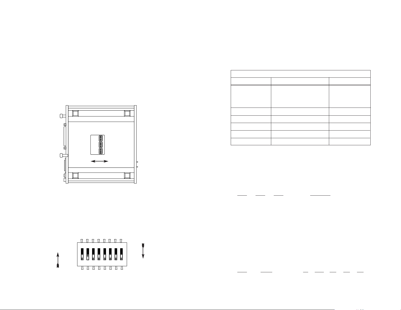
3.1 CONFIGURING THE HARDWARE DIP SWITCHES
The Model 2530 has 24 DIP switches that allow configuration to
wide range of applications. The 24 switches are grouped into three
eight-switch sets, and are externally accessible from the underside of
the Model 2530 (See Figure 1).
The three sets of DIP switches on the underside of the Model 2530
will be referred to as S1, S2, and S3. Figure 2 shows the orientation of
all DIP switches with respect to “ON”and “OFF”positions.
5
3.1.1 DIP Switch Set “S1”
The DIP switches on set S1 may be used to configure the DTE
rate, RTS/CTS delay, anti-stream timer, data format, character length
and Extended Signalling Rate (ESR) Default settings and detailed
descriptions for each switch in the set are shown below.
Switches S1-1, S1-2, and S1-3: DTE Rate
Use Switches S1-1 and S1-2 to configure the DTE rate of the
Model 2530. This rate represents the synchronous or asynchronous
rate at which the DTE must connect to Model 2530’s
QuikConnect™
interface.
S1-1 S1-2 S1-3 DTE Rate
On On On 2.4 kbps
On On Off 4.8 kbps
On Off On 9.6 kbps
Off On Off 19.2 kbps
Off On On 38.4 kbps
Off Off Off DTE Rate = Line Rate
Switch S1-4: RTS/CTS Delay
The RTS/CTS delay is the amount of time it takes for CTS to
change logic state following an RTS transition. Use Switch S1-4 to
select the RTS/CTS delay (measured in
msec
.).
S1-4 Delay 56 19.2 9.6 4.8 2.4
Off Normal 0.3 0.9 1.9 3.8 7.5
On Extended 1.3 3.8 7.5 15 30
6
Figure 1. Underside of Model 2530, Showing Location of DIP Switches
Front
Back
S2
S3
S1
ON
OFF
Figure 2. Close Up of Configuration Switches (all three sets are identical in appearance)
ON
OFF
S1 SUMMARY TABLE
Position Function Factory Default
S1-1 DTE Rate Off
S1-2 DTE Rate Off
S1-3 DTE Rate Off
S1-4 RTS/CTS Delay Off Normal
S1-5 Anti-Stream Timer Off Off
S1-6 Data Format Off Synchronous
S1-7 Character Length Off 10 Bits
S1-8 Extended Signal Rate Off Off
DTE Rate
equals
Line Rate
}
12345678
ON
12345678
12345678
ON
ON
ON
12345678

Switch S1-5: Anti-Stream Timer
The anti-stream timer protects multidrop networks from a drop that
is continuously transmitting. If the DTE keeps RTS raised for more
than the Time Value in seconds, the timer forces RTS off internally.
This allows the rest of the multidrop network to resume operation. The
CSU/DSU remains in the forced-off condition until the terminal drops
RTS. Use Switch S1-5 to enable the timer.
Timer Value in Sec at Various Line Rates
S1-5 Timer 56 19.2 9.6 4.8 2.4
On Disabled
not applicable
Off Enabled 2 4 8 15 30
Switch S1-6: Data Format
Use Switch S1-6 to configure the Model 2530 for synchronous or
asynchronous connection to the DTE.
S1-6
Setting
Off Synchronous
On Asynchronous
Switch S1-7: Asynchronous Character Length
Set Switch S1-7 to configure the total number of asynchronous
bits per asynchronous character (when Switch S1-6 is set to “On”).
S1-7
Setting
Off 10 bits
On 11 bits
NOTE: The total asynchronous character is determined by sum of
all start bits, data bits, stop bits and parity bits. For instance:
1
start bit + 8data bits + 1stop bit + 0parity bits = 10
bits
7
Switch S1-8: Extended Signaling Rate
Use S1-8 to configure the frequency tolerence the Model 2530
“looks for” in asynchronous data rates (i.e., the actual variance from a
given frequency level the Model 2530 Series will tolerate).
S1-8 Setting
Off -2.5% to +1%
On -2.5% to +2.3%
3.1.2 DIP Switch Set “S2”
The DIP switches on set S2 may be used to configure the line
rate, clock mode, force RTS, and DSR status during local loop. Default
settings and detailed descriptions for each switch in the set are shown
below.
Switches S2-1, S2-2 and S2-3: Line Rate
Use Switches S2-1, S2-2, and S2-3 to configure the signalling rate
on the line (RJ-48S port). The setting should match the speed of your
digital service.
S2-1
S2-2 S2-3 Line Rate
On On On 2.4 kbps
On On Off 4.8 kbps
On Off On 9.6 kbps
On Off Off 19.2 kbps
Off On On 56 kbps
Off On Off 64 kbps
Off Off Off Forces configuration
pointer to default to
hardware control.
8
SW2 SUMMARY TABLE
Position Function Factory Default
SW2-1 Line Rate Off
SW2-2 Line Rate On
SW2-3 Line Rate On
SW2-4 Clock Mode Off
SW2-5 Clock Mode Off
SW2-6 Force RTS Signal Off Disabled
SW2-7 DSR During Local Loop Off Off
SW2-8 Circuit Assurance Off Disabled
Network
56 kbps
}
}

Switches S2-4 and S2-5: Clock Mode
Use Switches S2-4 and S2-5 to set the source of Model 2530’s
transmit clock.
S2-4
S2-5 Clock Mode Description
Off On External (DTE) Transmit clock derived
from terminal interface
Off Off Network (Looped) Transmit clock derived
from the received line
signal; Use this mode
for Dedicated DDS
operation
On On Internal (Master) Transmit clock derived
internally
On Off Campus Clock Transmit clock derived
from the received line
signal. Allows remote
device (in
campus
clock
mode) to initiate
V.54 loopback. For use
only in campus shorthaul configuration.
(Note: Local device must
be set in
internal
clock
mode.)
Switch S2-6: Force RTS
Use S2-6 to force the transmitter ON, thereby ignoring the DTE’s
RTS signal. In the Off position, RTS controls the transmitter by forcing
it to send either the DTE data or an idle pattern.
S2-6
RTS Description
On Forced On Transmitter is always ON
Off Follows The RTS input controls the
DTE Signal transmitter
NOTE: At 64 kbps Force RTS is always on.
9
Switch S2-7: Data Set Ready During LOCAL Loopback Test
Use Switch S2-7 to control the behavior of the DSR signal at the
DTE interface during the local loopback test.
S-3 Setting
On DSR is on during local line loop
Off DSR is off during local line loop
Switch S2-8: Circuit Assurance
On dedicated circuits, the transmitter and the CTS output can be
configured to go ON only when a working communication circuit is
established. If Circuit Assurance is used, enable it on only one end of
the communication link. Use Switch S2-8 to configure circuit assurance.
Circuit
S2-8
Assurance Description
On Enabled CTS will go low and the
transmitter will be held off if the
receiver is in the No Signal state
or CD is low
Off Disabled The transmitter and CTS will
operate without regard to the
receiver state
10
Important:
For X.21 or Async campus short haul modem applications,
please configure one Model 2530 for
internal clock mode and the other
Model 2530 for receive recover clock
mode.

3.1.3 DIP Switch Set “S3”
The configuration switches on S3 set the BER Test pattern,
response to remote loop, front panel switch activation, DTE loop
request, and control port speed. The default settings and detailed
descriptions for each switch in the set are shown below.
Switch S3-1: Test Pattern
Use Switch S3-1 to set the V.52-compliant pattern used to test the
Model 2530. The two test options are the 511 and 2047 BER patterns
(For descriptions of the 511 and 2047 BER options, please refer to
Section 5.4).
S3-2
Setting
Off 511 Pattern
On 2047 Pattern
Switch S3-2: Response to RDL Request
Use Switch S3-2 to allow Model 2530 to enter the Remote Digital
Loopback diagnostic test when requested to do so by the remote
Model 2530 For example, when Switch S1-8 is set to “ON”, it will enter
RDL mode (See Section 5.3.2) when requested to do so by the remote
Model 2530.
S3-2
Setting
Off Response to RDL Request Enabled
On Response to RDL Request Disabled
11
Switch S3-3: Front Panel Switch Enable/Disable
Use Switch S3-3 to enable or disable the front panel switches.
S3-3
Activation Description
Off Enabled Front panel switches may be used
to activate/terminate diagnostics
On Disabled Front panel switches will have no
effect on operation of the unit
Switch S3-4: DTE Loop Request Line Enable/Disable
Use Switch S3-4 to activate or deactivate DTE control of the loop-
back diagnostic modes and BER test patterns.
DTE TM Line
S3-4
Activation Description
Off Enabled DTE Loop request lines may be
used to activate/terminate
diagnostics.
On Disabled DTE loop request lines will
have no effect on operation of
the unit.
Switches S3-5 and S3-6:
Reserved for Future Use
Switches S3-5 and S3-6 are
reserved for future use
and must
remain in the OFF position.
Switches S3-7 and S3-8: Control Port Data Rate
Use Switches S3-7 and S3-8 to configure Model 2530’s control
port bit rate.
S3-7 S3-8 Setting
On Off 9.6 kbps
Off Off 19.2 kbps
12
S3 SUMMARY TABLE
Position Function Factory Default
S3-1 Test Pattern Off 511
S3-2 RDL Response Off Enabled
S3-3 Front Panel Switches Off Enabled
S3-4 DTE Loop Request On Disabled
S3-5
Reserved for Future Use
Off
S3-6
Reserved for Future Use
Off
S3-7 Control Port Speed Off
S3-8 Control Port Speed Off
19.2 kbps
}

3.2 CONFIGURING THE SOFTWARE SWITCHES
The Model 2530 features a menu-driven command system that
allows you to configure the unit. Follow the instructions below to configure the Model 2530 using the software switches:
1) Connect the serial RS-232 port of a VT100 or similar DTE
with terminal emulation to the EIA/TIA-561l port of the Model
2530. To construct an RS-232 to EIA-561 patch cable, refer to
the control port pinout diagram in Appendix D. Refer to
Appendix C to order a pre-made cable.
2) Power up the terminal and set its RS-232 por t as follows:
19,200 bps (or as defined by Switch S3-7 and S3-8)
8 data bits, 1 stop bit, no parity
ANSI, VT-100 emulation
3) Power up the Model 2530.
4) After the Model 2530 is powered on, the control port will display the following login screen:
6) Enter the password 2530 Password. The initial login password is:
PATTON
NOTE: We recommend that you change this password after
the initial login.
7) The 2530 will then display the MAIN MENU screen.
13
3.2.1 Introduction to MAIN MENU
The MAIN MENU shows the Model 2530 configuration options.
This section describes each of the listed selections.
HELPFUL HINTS
1. To make a selection, key the highlighted letter that corresponds to a menu selection.
2. To execute the selection, type <enter/CR>
3. Select g Save Changes from MAIN MENU after making
modifications to any Model 2530 parameter. Otherwise,
changes will be lost when the 2530 is turned off.
4. The 2530 will display its control status as “UNDER HARDWARE CONTROL” or “UNDER SOFTWARE CONTROL” in the
upper right hand corner of the MAIN MENU screen.
14
Enter Password: *****
TOP LEVEL MANAGEMENT UNDER SOFTWARE CONTROL
a Software Control
b Hardware Control
c Display Hardware Configuration
d Software Configuration
e Diagnostics/Statistics
f Change Password
g Save Changes
h Logoff
Select [Highlighted Letter] Go To Sub-menu [CR]
g

Software Control
Select “Software Control” from MAIN MENU to place the Model
2530 under software switch control. When the 2530 is under software
switch control, the hardware switch configuration (Switches S1, S2, S3
and and front panel switches) will not affect the operation of the unit.
Hardware Control
Select “Hardware Control” From MAINMENU to place the Model
2530 under hardware switch control. When the 2530 is under hardware
control, the software switch configuration will not affect the operation of
the unit.
Display Hardware Configuration
Select “Display Hardware Configuration” from MAIN MENU to display the configuration of hardware Switches S1, S2 and S3. Please
refer to Section 3.1 to review the DIP switch definitions.
15
Software Configuration
Select Software Configuration from MAIN MENU to display the current settings of the software switches. The software switches control
the same parameters described in Section 3.1 Configuring the
Hardware Switches. Please refer to section 3.1 to review the hardware switch definitions.
To modify any of the parameters listed above:
1. Key the highlighted letter that corresponds to a menu selection.
2. Press [Space Bar] until the desired value is highlighted.
3. Press <Enter/CR> to select the desired value.
16
a
b
c
Hardware Configuration (Display Only)
Line Rate 56 kbps
Rate adapter 19.2 kbps
Transmit Clock Source Network
Data Format Asynchronous
Character Length 10 Bits
Extended Signal Rate Normal
RTS/CTS delay Extended
Forced RTS Off
Anti-Stream Timer On
DSR Loop Status On
Circuit Assurance On
Front Panel Switches Enabled
Response to Remote Loop Enabled
DTE loop Request Disabled
Test Pattern 2047
Control Port Speed 19.2 kbps
Exit = [ESC] Refresh = [ r ]
d
Software Configuration
a Line Rate 56.0 kbps
b Rate Adapter/DTE Rate 19.2 kbps
c Transmit Clock Source Network
d Data Format Asynchronous
e Character Length 11 bits
f Extended Signalling Rate Extended
g RTS/CTS Delay Extended
h Forced RTS Off
i Anti-Stream Timer On
j DSR Loop Status On
k Circuit Assurance On
l Response to Remote Loop Off
m DTE Loop Request Off
n Control Port Speed 19.2 kbps
Select=[Highlighted Letter] Scroll Options=[Space Bar]
Exit = [ESC] Refresh screen = [ r ]

Diagnostics/Statistics
Select “Diagnostics/Statistics” from MAIN MENU to monitor or activate/deactivate Model 2530’s V.52 BER test patterns and V.54 loop
diagnostics. These diagnostics and statistics can help to verify link
integrity and isolate communication difficulties .
Active Loop Conditions are shown below:
Local Local Analog Loopback test is active.
Remote Remote Digital Loopback is active.
Under Remote Loop The remote Model 2530 has initiated a
Remote Digital Loopback test.
Under CO Loop The CO has initiated a CSU Loop
17
Test Patterns are shown below:
511 The 511 BER test is active.
511/E The 511/E BER test is active.
2047 The 2047 BER test is active.
2047/E The 2047/E BER test is active.
To activate a loop diagnostic or test patter n:
1. Make sure DIP Switch 3-4 is ON.
1. Key the highlighted letter that corresponds to a menu selection.
2. Press [Space Bar] until the desired value is highlighted.
3. Press <Enter/CR> to select the desired value.
Change Password
Select Change Password to change the active password of the
software configuration menu (see below).
To change the active password:
a. Enter from one (1) to six (6) alphanumeric ASCII characters
(0...9, a...z, or A...Z) at the
New Password>_ prompt.
b. Press <Enter/CR>
18
e
Diagnostics and Statistics
a Select Acti ve Loop Local
b Select Test Pattern None
Status
Active Loop Local
Active Test Pattern None
Errored Seconds 0000
CD ON
RTS ON
CTS ON
Select=[Highlighted Letter] Scroll Options=[Space Bar]
Exit=[ESC] Change Selection=[CR]
Clear Errored Seconds = [ c ]
TOP LEVEL MANAGEMENT UNDER SOFTWARE CONTROL
a Software Control
b Hardware Control
c Display Hardware Configuration
d Software Configuration
e Diagnostics/Statistics
f Save Changes
g Logoff
h Change Password
New Password>_
f

Save Changes
Select Save Changes to save any modifications in the previous sections. Changes not saved will be lost when the Model 2530 is powered
OFF.
Logoff
Select Logoff to exit the Software Configuration. After selecting
Logoff, the 2530 will re-display the login screen.
19
4.0 INSTALLATION
After the Model 2530 has been properly configured it may be connected to the serial port, twisted pair interface, and to the power
source. This section tells you how to make these connections.
4.1 CONNECTING THE SERIAL PORT
The serial port interface on the Model 2530 uses interchangeable
QuikConnect™
Modules to connect to your DTE. Each
QuikConnect™
Module has a 50-pin card edge connector on one side
and a serial port interface on the other. Figure 3 below shows how a
QuikConnect™
Module plugs into the back of the Model 2530.
4.1.1 Changing
QuikConnect™
Modules
When you purchase a Model 2530, it should be shipped to you
with the appropriate
QuikConnect™
Module already installed. If you
need to install a different
QuikConnect™
Module, follow these steps:
Removing the Existing
QuikConnect™
Module
1) Turn the power switch off. Leave the power cord plugged into a
grounded outlet to keep the unit grounded.
2) Loosen the two thumbscrews on the module by turning them
counter-clockwise.
3) Grasp the two thumbscrews and gently pull the module from
the unit. Apply equal force to the thumbscrews to keep the
module straight during the removal process.
20
g
h
Figure 3. Installation of Model 2530 Plug-in Serial Interface Module
Line
Interface Port
1 ON
0 OFF

Installing the New
QuikConnect™
Module
1) Make sure the power switch is off. Leave the power cord
plugged into a grounded outlet to keep the unit grounded.
2) Hold the module with the faceplate toward you and align the
module with the guide slots in the rear panel of the Model
2530.
3) While keeping the module’s faceplate parallel with the Model
2530 rear panel, slide the module straight in–so that the card
edge contacts line up with the socket inside the chassis.
NOTE: The card-edge connector should meet the socket when
it is almost all the way into the chassis. If you encounter much
resistance, remove the module and repeat steps 2 & 3.
4) With the card edge contacts aligned with the socket, firmly seat
the module by using your thumbs to apply pressure directly to
the right and left edges of the module faceplate. Applying moderate and
even
pressure should be sufficient to seat the mod-
ule. You should hear it “click” into place.
5) To secure the module in place, push the thumbscrews into the
chassis and turn the screws clockwise to tighten.
4.1.2 Connection to a “DTE” Device
The serial port on most
QuikConnect™
interface modules (all
except the X.21 module) is hard-wired as a DCE. Therefore these
modules “want” to plug into a DTE such as a terminal, PC or host.
When making the connection to your DTE device, use a straight
through cable of the shortest possible length—we recommend 6 feet
or less. When purchasing or constructing an interface cable, please
refer to the pin diagrams in Appendix C as a guide.
4.1.3 Connection to a “DCE” Device
If the Model 2530’s
QuikConnect™
interface module is hard-wired
as a DCE (all except the X.21 module), you must use a
null modem
cable when connecting to a modem, multiplexer or other DCE device.
This cable should be of the shortest possible length—we recommend 6
feet or less. When purchasing or constructing a null modem interface
cable, use the pin diagrams in Appendix D as a guide.
NOTE: Pin-out requirements for null modem applications vary
widely between manufacturers. If you have any questions about a
specific application, contact Patton Technical Support.
21
4.1.4 Configuring the X.21
QuikConnect™
Module
The serial port on the X.21
QuikConnect™
Module is default wired
as a DCE, but may be switched to a DTE. This is done by reversing
the orientation of the DCE/DTE strap, as described below:
To reverse DCE/DTE orientation, remove the module according to
the instructions in Section 4.1.1. The DCE/DTE strap is located on the
bottom side of the module’s PC board. The arrows on the top of the
strap indicate the configuration of the X.21 port (for example, if the
DCE arrows are pointing toward the DB-15 connector, the X.21 port is
wired as a DCE). Reverse the DCE/DTE orientation by pulling the
strap out of its socket, rotating it 180ºº, then plugging the strap back into
the socket. You will see that the DCE/DTE arrows now point in the
opposite directions, showing the new configuration of the X.21 port.
Re-install the module according to the instructions in Section 4.1.1.
4.2 CONNECTING THE TWISTED PAIR INTERFACE
The Network Interface is an 8 position modular connector. Connect
this port to the RJ-48S jack provided by the digital data service
provider. If the Model 2500 Series is being used for private short haul
communication, the twisted pair cable will connect to this port. See
Appendix C for the pin assignments of this connector.
The RJ-48S connector on the Model 2530’s twisted pair interface is
pre-wired for a standard TELCO wiring environment. The signal/pin
relationships are shown in Figure 4 below.
22
Figure 4. Model 2530 twisted pair line interface.
1 (TX+)
2 (TX-)
3 (N/C)
4 (N/C)
5 (N/C)
6 (N/C)
7 (RX+)
8 (RX-)
1
2
3
4
5
6
7
8

4.3 CONNECTING POWER
The Model 2530 is available with two power supply options:
4.3.1 Connecting to an AC Power Source
Universal Interface AC Power Supply option (Model 2530-UI)
operates in environments ranging from 100 to 253 VAC, with no re-configuration necessary (see Appendix B for available domestic and international power cords). To connect the standard or universal power
supply, follow these steps:
1) Attach the power cord (supplied) to the shrouded male IEC-
320 connector on the rear of the Model 2530.
2) Plug the power cord into a nearby AC power outlet.
3) Turn the rear power switch ON.
4.3.2 Connecting to a DC Power Source
DC Power Supply option (Model 2530-DC) operates in 48 VDC
environments and is equipped with a 3-pin “terminal strip” style connector. The 48 VDC power supply option uses a 3-pin terminal block
with spring-type connectors. Please refer to the Model 2530 Series
Service Manual for further instructions.
23
5.0 OPERATION
After the Model 2530 is properly configured and installed, it should
operate transparently. This sections describes power-up, the LED status monitors, and the built-in loopback test modes.
5.1 POWER-UP
To apply power to the Model 2530, first be sure that you have read
Section 4.3, and that the unit is connected to the appropriate power
source. Then power-up the unit using the rear power switch.
5.2 LED STATUS MONITORS
The Model 2530 features twenty-four (24) front panel LEDs that
monitor the line rate, power, the DTE signals, the network connection
and test modes. Figure 5 (below) shows the front panel location of
each LED. Following Figure 5 is a description of each LEDs function.
Power Glows green when power is present.
Line Rate The corresponding LED will glow red to indicate the
selected line rate.
TD & RD Glows red to indicate an idle condition of Binary
“1” data on the respective terminal interface signals.
Green indicates Binary “0” data.
RTS Glows green to indicate that the Request to Send
signal from the DTE is active.
CTS Glows green to indicate that the Clear to Send
signal from the modem is active.
DSR Glows green to indicate that the 2530 has asserted
the Data Set Ready signal.
DCD Glows red if no carrier signal is being received from
the remote modem. Green indicates that the remote
modem’s carrier is being received.
24
WARNING! There are no user-serviceable parts in the
power supply section of the Model 2530. Voltage setting
changes and fuse replacement should only be performed by
qualified service personnel. Contact Patton Electronics
Technical support at (301) 975-1007, via our website at
http://www.patton.com, or by e-mail at support@patton.com,
for more information.
Figure 5. Model 2530 Front Panel Installation of Model
Power
2.4 kbps
Model 2530
4.8 kbps
9.6 kbps
19.2 kbps
38.4 kbps
56 kbps
64 kbps
RD
RTS
CTS
DCD
DSR
DTR
No Signal
Error
Line Rate
TD
DTE Status
Line
Status
Test Mode
Local -
Normal -
Remote -
DigiLink-V
Test Modes
Loop Pattern
Dedicated CSU/DSU
- Errored
- Off
- Normal
Control Port

DTR Glows green to indicate that the Data Terminal
Ready signal from the terminal is active.
ER Glows red to indicate the likelihood of a Bit Error in
the received signal. .
TM Glows red to indicate that the Model 2530 has
been placed in Test Mode. The unit can be placed in
test mode by the local or remote user.
NS Glows red to indicate that the local Model 2530 has
not yet connected with the C.O. (or to the remote
Model 2530 when used in campus short haul
application).
5.3 LOOP (V.54 & TELCO) DIAGNOSTICS
The Model 2530 offers three V.54 loop diagnostics and is compatible with two Telco loop diagnostics. Use these diagnostics to test the
CSU/DSU and any communication links. These tests can be activated
physically from the front panel, or via signals on the
QuikConnect™
interface.
5.3.1 Operating Local Analog Loopback (LAL)
The Local Line Loopback (LAL) test checks the operation of the
local Model 2530, and is performed separately on each unit. As shown
in Figure 6, below, any data sent to the local Model 2530 in this test
mode will be echoed (returned) back to the user device (i.e., characters
typed on the keyboard of a terminal will appear on the terminal
screen).
To perform a LLB test, follow these steps:
1. Activate LAL. This may be done in one of two ways:
a. Move the front panel toggle switch UP to “Local”;or,
b. Activate the “LL” signal on the DTE. If you are not sure
which lead is the “LL” signal, please refer to Appendix D.
25
2. Verify that the data terminal equipment is operating properly
and can be used for a test.
3. Perform a V.52 BER (bit error rate) test as described in
Section 5.3.3. If the BER test equipment indicates no faults,
but the data terminal indicates a fault, follow the manufacturer’s checkout procedures for the data terminal. Also, check
the interface cable between the terminal and the Model 2530.
5.3.2 Operating Remote Digital Loopback (RDL)
The Remote Digital Loopback (RDL) test checks the performance
of both the local and remote Model 2530s, as well as the communication link between them. Any characters sent to the remote Model 2530
in this test mode will be returned back to the originating device (i.e,
characters typed on the keyboard of the local terminal will appear on
the local terminal screen after having been passed to the remote
Model 2530 and looped back).
To perform an RDL test, follow these steps:
1. Activate RDL. This may be done in two ways:
a. Move the front panel toggle switch DOWN to “Remote”;
b. Activate the “RL” signal on the DTE. If you are not sure
which lead is the “RL” signal, please refer to Appendix D.
2. Perform a bit error rate test (BERT) using the internal V.52
generator (as described in Section 5.4), or using a separate
BER Tester. If the BER test indicates a fault, and the Local
Line Loopback test was successful for both Model 2530s, you
may have a problem with the twisted pair line between the
modems. You should then check the twisted pair line for proper connections and continuity.
26
Figure 6. Local Line Loop
Local 2530
Figure 7. Remote Digital Loop
Local 2530
Remote 2530

5.3.3 Telco T esting
The digital service provider’s central office can perform CSU
diagnostic testing. These diagnostics allow the central office to evaluate the circuit operation without making visits to the customer’s premises.
CSU Loop
The CSU loop is activated when the central office reverses the DC
sealing current that flows between the Transmit (TX) and Receive (RX)
pairs. The Model 2530 recognizes this and loops the signals on the
RX pairs back to the central office on the TX pair. While the CSU loop
is activated, the TM light is illuminated.
27
5.4 BIT ERROR RATE (V.52) DIAGNOSTICS
The Model 2530 offers two V.52 Bit Error Rate (BER) test patterns.
These test patterns may be invoked along with the LAL and RDL tests
to evaluate the unit(s) and the communication links.
When a 511 or 2047 test is invoked, the 2530 generates a pseudo-random pattern of 511 bits (or 2047 bits) using a mathematical polynomial. The receiving Model 2530 then decodes the received bits
using the same polynomial. If the received bits match the agreed upon
pseudo-random pattern, then the 2530(s) and the communication
link(s) are functioning properly.
511 Initiates a built-in 511 bit pseudo-random
pattern generator and detector.
511 with Errors Initiates a built-in 511 bit pseudo-random
pattern generator and detector. The test
pattern generator also injects
intentional
errors
approximately twice per second,
causing the Error LED to blink.
2047 Initiates a built-in 2047 bit pseudo-random
pattern generator and detector.
2047 with Errors Initiates a built-in 2047 bit pseudo-random
pattern generator and detector. The test
pattern generator also injects
intentional
errors
approximately twice per second,
causing the Error LED to blink.
To perform a V.52 BER test, follow these steps:
1. Select the 511 or 2047 test patter n using Switch 3-1.
1. Locate the “Pattern” toggle switch on the front panel of the
2530 and move it DOWN to “Normal. This activates the V.52
transmission and reception of the selected test pattern. If
there are errors in the received pattern, the error LED will
blink accordingly.
2. If the above test indicates no errors are present, move the
toggle switch UP to “Errored”, activating the BER test with
intentional errors. If the test is working properly, the local
modem's red error LED blink approximatley twice per second.
28
Figure 7. CSU loop
CSUDSU Digital Network

APPENDIX A
PATTON MODEL 2530 SPECIFICATIONS
Compatibility: AT&T 62310
DDS Line Interface: Externally accessible RJ-48S
Transmission Format: Synchronous or asynchronous
Transmission Line: Two unconditioned twisted pair
Clock Options: Internal, external, receive loopback and
campus
DTE/DCE Interfaces: Patton
QuikConnect™
Modules: EIA
RS-232/CCITT V.24, RS-232/530,
CCITT V.35 and CCITT X.21
DTE/DCE Speeds: Synchronous: 2.4, 4.8, 9.6, 19.2, 56,
and 64 kbps;
Asychronous: 2.4, 4.8, 9.6, 19.2, 38.4,
and 57.6 kbps
Diagnostics: V.54 compliant local and remote
loopbacks;V.52 compliant 511 and
2047 BER tests
Front Panel LEDs: DDS line rates (2.4, 4.8, 9.6, 19.2,
56, and 64 kbps), Power, TD, RD,
RTS, CTS, DCD, DSR, DTR, No
Signal, Test Mode, Error indication.
Distance: -49 dBm receiver sensitivity or better
RTS/CTS Delay: 0 ms/30 ms
Front Panel Switches: Loopback indication and Bit Error Rate
Test
Power: Universal Input (UI): 100 - 253VAC
Input; DC: 18VDC - 72VDC, 48V
Nominal
Temperature Range: 32-122°F (0° -50°C)
Altitude: 0-15,000 feet
Humidity: 5 to 95% noncondensing
Dimensions: 7.3” x 6.6” x 1.62” (185mm x 168mm x
41mm)
Weight: 2.01 lbs. (1.0kg)
Approvals: FCC Part 68, FCC Part 15, UL and cUL
Approvals.
Surge Protection: 600W Power Dissipation
Lightning Protection: Gas Tube
Isolation: 1500V via Isolation Transformers
29
APPENDIX B
PATTON MODEL 2530 FACTORY REPLACEMENT PARTS
AND ACCESSORIES
Patton Model # Description
IM1/A...............................V.24 with DB25F
IM1/B...............................RS422/RS530 with DB25F
IM1/C ...............................V.35 with M34F
IM1/D ...............................X.21 with DB15F
IM1/E...............................V.35 with DB25F
IM1/F...............................G.703 with RJ45
IM1/G...............................High Speed Asynchronous with DB-25F
0805US ...........................American Power Cord
0805EUR .........................European Power Cord CEE 7
0805UK ...........................United Kingdom Power Cord
0805AUS.........................Australia/New Zealand Power Cord
0805DEN .........................Denmark Power Cord
0805FR............................France/Belgium Power Cord
0805IN .............................India Power Cord
0805IS.............................Israel Power Cord
0805JAP ..........................Japan Power Cord
0805SW...........................Switzerland Power Cord
07M2530 .........................User Manual
07M1090SVC..................1090 Series Ser vice Manual
30
Data
Rate
64 Kbps 7.1 4.9 3.4
56 Kbps 7.6 5.2 3.6
19.2 Kbps 8.7 6.2 4.5
9600 bps 10.4 7.7 5.8
4800 bps 13.7 10.6 9.7
2400 bps 15.1 14.2 9.1
Model 2530 Series Distance Table (miles)
Wire Gauge
22 24 26

APPENDIX C
PATTON MODEL 2530 INTERFACE PIN ASSIGNMENT
RS-232, RS-530 Interface Pin Description
(DB-25 Female Connector)
(DCE Configuration)
Pin # Signal
1 FG (Frame Ground)
2 TD (Transmit Data)
3 RD (Receive Data)
4 RTS (Request to Send)
5 CTS (Clear to Send)
6 DSR (Data Set Ready)
7 SGND (Signal Ground)
8 CD (Carrier Detect)
9 RC/ (Receive Timing-B)
10 CD/ (Carrier Detect-B)
11 XTC/ (External Transmit Clock)
12 TC/ (Transmit Clock - B)
13 CTS/ (Clear to Send)
14 TD/ (Transmit Data-B)
15 TC (Transmit Clock)
16 RD (Receive Data)
17 RC (Receive Clock)
18 LLB (Local Line Loop)
19 RTS/ (Request to Send)
20 DTR (Data Terminal Ready)
21 DL (Remote Digital Loop)
22 DSR/ (Data Set Ready)
23 DTR/ (Data Terminal Ready - B)
24 XTC (External Transmit Clock)
25 TM (Test Mode)
31
APPENDIX C
PATTON MODEL 2530 INTERFACE PIN ASSIGNMENT
(Continued)
V.35 Interface
(M/34F Female Connector)
(DCE Configuration)
Pin # Signal
B ...........................SGND (Signal Ground)
C ...........................RTS (Request to Send)
D ...........................CTS (Clear to Send)
E ...........................DSR (Data Set Ready)
F............................CD (Carrier Detect)
H ...........................DTR (Data Terminal Ready)
L............................LLB (Local Line Loop)
M...........................TM (Test Mode)
N ...........................RDL (Remote Digital Loop)
P ...........................TD(Transmit Data-A)
R ...........................RD (Receive Data-A)
S ...........................TD/ (Transmit Data-B)
T............................RD/ (Receive Data-B)
U ...........................XTC (External Transmit Clock)
V ...........................RC(Receive Clock)
W...........................XTC/ (External Transmit Clock)
X ...........................RC/ (Receive Clock-B)
Y ...........................TC(Transmit Clock-A)
AA ..........................TC/ (Transmit Clock-B)
32

APPENDIX C
PATTON MODEL 2530 INTERFACE PIN ASSIGNMENT
(Continued)
X.21 Interface
(DB-15 Female Connector)
(DTE /DCE Configuration)
Pin # Signal
1. . . . . . . . . . . . Frame Ground
2. . . . . . . . . . . . T (Transmit Data-A)
3. . . . . . . . . . . . C (Control-A)
4. . . . . . . . . . . . R (Receive Data-A)
5. . . . . . . . . . . . I (Indication-A)
6. . . . . . . . . . . . S (Signal Element iming-A)
8 . . . . . . . . . . . SGND (Signal Ground)
9 . . . . . . . . . . . T/ (Transmit Data-B)
10 . . . . . . . . . . . C/ (Control-B)
11 . . . . . . . . . . . R/ (Receive Data-B)
12 . . . . . . . . . . . I/ (Indication-B)
13........................S/ (Signal Element Timing-B)
33
APPENDIX D
PATTON MODEL 2530 Pin Out Control Port
The 2530 control port is an 8 position connector, compliant with
EIA/TIA-561.
Pin Function RJ45 Pin No.
Ground 4
Receive data (to DTE) 5
Transmit data (from DTE) 6
34
 Loading...