

Page 1
USER
MANUAL
MODEL 2500RC Series
Models 2500RC, 2510RC
and 2520RC:
All-Rate CSU/DSU
Rack Mount Card
CERTIFIED
An ISO-9001
Certified Company
Part# 07M2500RC--D
Doc# 099011U
Revised 1/23/08
, Rev. E
SALES OFFICE
(301) 975-1000
TECHNICAL SUPPORT
(301) 975-1007
http://www.patton.com
Page 2

TABLE OF CONTENTS
Section Page
1.0 Warranty Information .............................................................2
1.1 Radio and TV Interference
1.2 FCC Information
1.3 CE Information
1.4 Service Information
2.0 General Information...............................................................5
2.1 Product Features
2.2 General Product Description
2.3 Supported Applications
3.0 Configuration .........................................................................7
3.1 Front Card Configuration - Hardware Switches
3.2 Front Card Configuration - Software Switches
3.3 Rear Card Configuration
4.0 Installation ...........................................................................26
4.1 The Model 1000R16 Rack Chassis
4.2 Installing the Model 2500RC Series into the Chassis
4.3 Wiring the Model 2500RC Series
5.0 Operation.............................................................................28
5.1 LED Descriptions
5.2 Status Displays
5.3 Loopback Test Modes
5.4 The V.52 BER Test Pattern Generator
5.5 Switched 56 Dialing Commands (Models 2510RC & 2520RC)
Appendix A - Specifications
Appendix B - Cable Recommendations
Appendix C - Factory Replacement Parts and Accessories
Appendix D - Interface Pin Assignments
Appendix E - Transmitter Clock Source During Test Loops
1
Page 3

1.0 WARRANTY INFORMATION
Patton Electronics warrants all Model 2500RC Series
components to be free from defects, and will—at our option—repair or
replace the product should it fail within one year from the first date of
shipment.This warranty is limited to defects in workmanship or
materials, and does not cover customer damage, abuse, or
unauthorized modification. This product contains no serviceable parts;
therefore the user shall not attempt to modify the unit in any way. If this
product fails or does not perform as warranted, your sole recourse shall
be repair or replacement as described above. Under no condition shall
Patton Electronics be liable for any damages incurred by the use of
this product. These damages include, but are not limited to, the
following: lost profits, lost savings and incidental or consequential
damages arising from the use of or inability to use this product. Patton
Electronics specifically disclaims all other warranties, expressed or
implied, and the installation or use of this product shall be deemed an
acceptance of these terms by the user. In the event the user detects
intermittent or continuous product malfunction due to nearby high
power transmitting radio frequency equipment, the user is strongly
advised to take the following steps: use only data cables with an
external outer shield bonded to a metal or metalized connector; and,
configure the rear card as shown in section 3.3. of this manual.
1.1 RADIO AND TV INTERFERENCE
The Model 2500 Series generates and uses radio frequency
energy, and if not installed and used properly—that is, in strict
accordance with the manufacturer's instructions—may cause
interference to radio and television reception. The Model 2500 Series
has been tested and found to comply with the limits for a Class A
computing device in accordance with the specifications in Subpart J of
Part 15 of FCC rules, which are designed to provide reasonable
protection from such interference in a commercial installation.
However, there is no guarantee that interference will not occur in a
particular installation. If the Model 2500 Series does cause
interference to radio or television reception, which can be determined
by disconnecting the cables, the user is encouraged to try to correct the
interference by one or more of the following measures: moving the
computing equipment away from the receiver, re-orienting the receiving
antenna, and/or plugging the receiving equipment into a different AC
outlet (such that the computing equipment and receiver are on different
branches).In the event the user detects intermittent or continuous
product malfunction due to nearby high power transmitting radio
frequency equipment, the user is strongly advised to take the following
steps: use only data cables with an external outer shield bonded to a
metal or metalized connector; and, configure the rear card as shown in
section 3.3.1 of this manual.
2
Page 4

1.2 FCC INFORMATION
The Model 2500 Series has been tested and registered in
compliance with the specifications in Part 68 of the FCC rules. A label
on the equipment bears the FCC registration number. You may be
requested to provide this information to your telephone company.
Your telephone company may make changes in its facilities,
equipment, operations or procedures that could affect the proper
operation of the Model 2500 Series. If this happens, the telephone
company should give you advance notice to prevent the interruption of
your service.
The telephone company may decide to temporarily discontinue
your service if they believe your Model 2500 Series may cause harm to
the telephone network. Whenever possible, they will contact you in
advance. If you elect to do so, you have the right to file a complaint
with the FCC.
If you have any trouble operating the Model 2500 Series, please
contact Patton Technical Support at (301) 975-1000. The telephone
company may ask you to disconnect the equipment from the telephone
network until the problem has been corrected or until you are certain
that the Model 2500 Series is not malfunctioning.
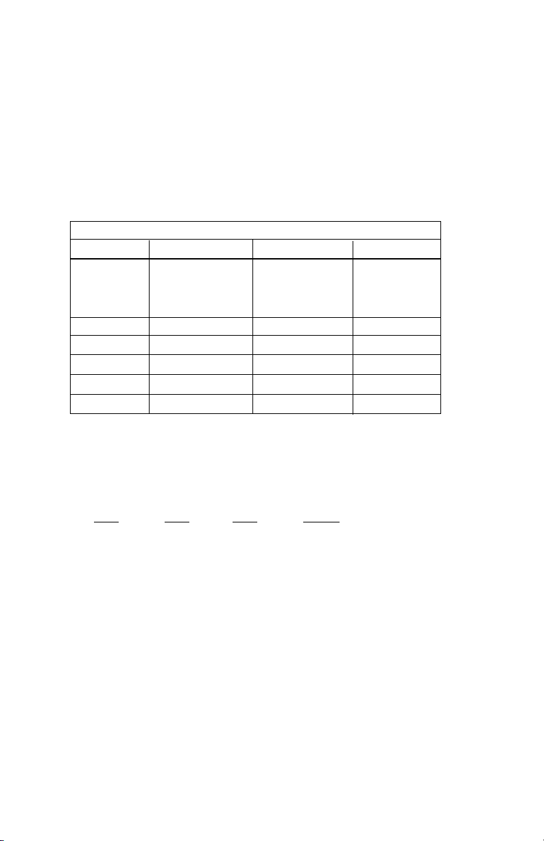
The following information may be required when applying to your
local telephone company for leased line facilities:
Service Digital Facility Service Order Network
T
ype Interface Code Code Jacks
2.4 Kbps Digital Interface 04DU5-24 6.0F RJ48S
4.8 Kbps Digital Interface 04DU5-48 6.0F RJ48S
9.6 Kbps Digital Interface 04DU5-96 6.0F RJ48S
56 Kbps Digital Interface 04DU5-56 6.0F RJ48S
NOTE: As of this publication date, 19.2 and 64Kbps digital
services have not been assigned Digital Facility Interface Codes.
1.3 CE NOTICE
The CE symbol on your Patton Electronics equipment indicates
that it is in compliance with the Electromagnetic Compatibility (EMC)
directive and the Low Voltage Directive (LVD) of the Union European
(EU). A Certificate of Compliance is available by contacting Technical
Support.
3 4
Page 5

1.4 SERVICE
All warranty and nonwarranty repairs must be returned freight
prepaid and insured to Patton Electronics. All returns must have a
Return Materials Authorization number on the outside of the shipping
container. This number may be obtained from Patton Electronics
Technical Support: (301) 975-1007; http://www.patton.com; or,
support@patton.com.
Notice: Packages received without an RMA number will not be
accepted.
Patton Electronics' technical staff is also available to answer any
questions that might arise concerning the installation or use of your
Patton Model 2500RC. Technical Service hours: 8AM to 5PM EST,
Monday through Friday.
Page 6

2.0 GENERAL INFORMATION
Thank you for your purchase of this Patton Electronics product.
This product has been thoroughly inspected and tested and is
warranted for One Year parts and labor. If any questions arise during
installation or use of the unit, contact Patton Electronics Technical
Support: (301) 975-1007; http://www.patton.com; or,
support@patton.com.
2.1 PRODUCT FEATURES
• Operates over 4-wire dedicated digital lines
• Supports rates of 56 Kbps and 64 Kbps and all sub rates
• Supports Switched 56 dialing
• Both RS-232 and V.35 rear interface cards available
• Features V.52 and V.54 compliant tests
• Nine easy-to-read LED indicators to monitor data signals
• Internal, external or received loopback clocking
• AT&T 62310 compliant
• Can be used as a high speed modem for private twisted pair
• Fits in Patton’s rack chassis and Cluster Boxes
• Made in the USA
2.2 GENERAL PRODUCT DESCRIPTION
The Model 2500RC Series CSU/DSUs operate either
synchronously or asynchronously over 4-wire circuits up to 64 Kbps.
Rate conversion allows operation with a variety of DTE devices.
Diagnostics include V.54 and V.52 loopback tests, as well as CSU
loops. Configuration is accomplished by either internal DIP switches or
RS-232 software switches (user provides terminal). Nine easy-to-read
function card LED indicators monitor data and control signals. Two rear
interface cards are available: DB-25 and RJ-48 or M/34 and RJ-48.
The Model 2500RC Series is AT&T compliant and supports DDS,
Switched 56, Clear Channel 64 and other digital services available from
major service providers including AT&T, Sprint and MCI. Dedicated
models can also be used as a high speed modem for private twisted
pair. The Model 2500RC Series is available in standalone or in rackcard versions (only rack card versions are covered in this manual).
5
Page 7

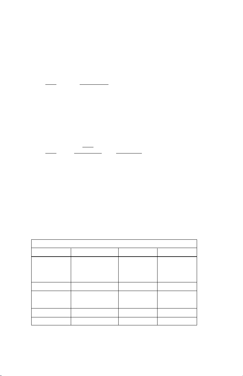
2.3 SUPPORTED APPLICATIONS
The Model 2500RC Series includes three units: the Model 2500RC
All-Rate CSU/DSU, the Model 2510RC Switched 56 CSU/DSU and the
Model 2520RC All-Rate/Switched 56 CSU/DSU. Depending upon the
unit selected, the Mode 2500RC Series supports three distinct modes
of operation. These are outlined in the descriptions and table below:
Dedicated DDS/Clear Channel Operation (Models 2500RC, 2520RC)
The unit can be easily configured for dedicated DDS/Clear Channel
operation by means of the dip switches on the bottom of the enclosure,
or by means of the software control port. Set the Line Rate to match
the rate of service to which you subscribe. Set the Mode switches for
Network Clocking. The Rate Converter and the Data Format options
should be set as required for your application. The remaining options
may need to be set depending on your terminal equipment and your
application.
Switched-56 Operation (Models 2510RC, 2520RC)
The unit can be used in Switched 56 applications. Set the Line
Rate to 56 Kbps. Set the Mode switches for Switched 56, and enable
Force RTS and Circuit Assurance. Dial or store a number using the
control port. The Rate Converter and the Data Format options should
be set as required for your application. The remaining options may
need to be set depending on your terminal equipment and your
application.
Campus Area Short Haul Operation (Models 2500RC, 2520RC)
The unit can also be used for campus area point-to-point short-haul
applications on private twisted-pair wires. Set the Line Rates the same
on both units. Set the Mode switch for the appropriate Transmit Clock
Mode for your application. Internal, External and Looped Clock Modes
are available. Set the remaining options as needed by your terminal
equipment or your application.
MODEL 2500RC SERIES APPLICATIONS
2500RC 2510RC 2520RC
Line Rate Switches All line rates 56 Kbps only All line rates
Supported Supported
Mode Switches Supports all modes Switched 56 only All modes
except Sw-56 Supported
Dialing
Commands
Not Supported Supported Supported
6
Page 8
3.0 CONFIGURATION
Before you can install and operate your Model 2500RC Series
CSU/DSU, you must configure both the front and rear cards. The
Model 2500RC Series has two sets of eight switches (S1 and S2), a
reversible interface driver board and two Rotary Address switches
(MSD and LSD). The 2500RC also has software switches which may
be configured with the Patton Model 1000CC control card (not
supplied), using a VT-100 type RS-232 terminal. Rear card
configuration is accomplished by means of hardware straps.
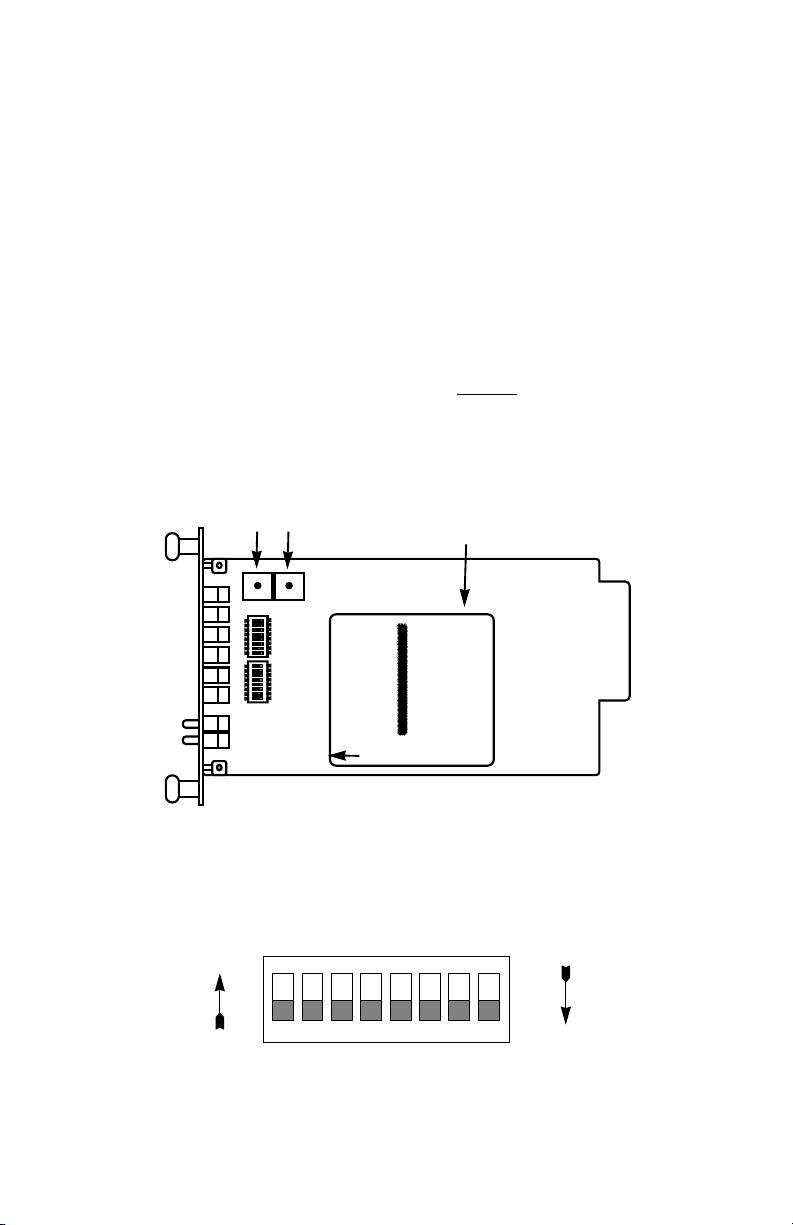
3.1 FRONT CARD CONFIGURATION - HARDWARE SWITCHES
The Model 2500RC Series front card defaults
to the use of
hardware switches for configuration. Hardware switches consist of
two eight-position DIP switches, and two rotary switches (see Figure 1,
below).
Rotary Address
Switches
LSD
MSD
SW2
ON
12345678
SW1
ON
12345678
Interface
Driver
Board
FRONT
THIS SIDE UP FOR V.35
Figure 1. Model 2500RC Series front card, showing location of switches
The two sets of DIP switches on the Model 2500 Series are referred to
as S1, S2. As Figure 2 shows, the orientation of all DIP switches is the
same with respect to “ON” and “OFF” positions.
ON
NOTE: The ON position is oriented toward the front of the Model 1092RC.
ON
12345678
Figure 2. Close up of DIP switches showing ON/OFF positions.
OFF
Page 9
3.1.1 Switch Set “S1”
The configuration switches on switch set S1 allow you to specify
Line Rate, Circuit Assurance, RTS, Character Length, Data Format and
DSR Loop Status. The table below summarizes S1 switch settings,
including the factory defaults. Following the table are descriptions of
each switch setting.
SWITCH SET S1 SUMMARY TABLE
Position Function Factory Default Exceptions
S1-1 Line Rate Off
S1-2 Line Rate On
S1-3 Line Rate On
S1-4 Circuit Assurance Off Disabled
S1-5 RTS Off Forced On
S1-6 Character Length Off 10-Bit
S1-7 Data Format Off Synchronous
S1-8 DSR Loop Status Off DSR Off
Switches S1-1. S1-2 and S1-3: Line Rate
These switches control the signalling rate on the line or RJ-48S
port of the unit. They should be set to match the speed of your digital
service.
56,000 bps
}
Model 2510:Enabled
S1-1
On On On 2.4 Kbps
On On Off 4.8 Kbps
On Off On 9.6 Kbps
On Off Off 19.2 Kbps
Off On On 56 Kbps
Off On Off 64 Kbps
Off Off Off Force configuration
For line rates of 56 and 64 kbps, it is possible to operate the DTE
interface at a lower rate. To do this, set these switches to 56 or 64 kbps
and set the Rate Converter/DTE Rate switches as required.
S1-2 S1-3 Setting
pointer to default to
Hardware Switches
(See Section 3.2)
87
Page 10

Switch S1-4: Circuit Assurance
The transmitter and the CTS output can be configured to go On
only when a working communication circuit is established. If Circuit
Assurance is used, enable it on only one end of the communication link.
Circuit Assurance should be enabled in Switched 56 mode.
Circuit
S1-4
Assurance Description
On Enabled CTS will go low and the transmitter
will be held off if the receiver is in
the No Signal state or CD is low
Off Disabled The transmitter and CTS will
operate without regard to the
receiver state
Switch S1-5: RTS
The RTS input can be forced on, ignoring the terminal’s RTS
signal. RTS controls the transmitter by either sending the user’s data
or sending an idle code.
S1-5
RTS Description
Off Forced On An On (high) condition is trans-
mitted regardless of the state of
this unit’s RTS input
On Follows DTE The RTS input controls the
transmitter
Switch S1-6: Character Length
In asynchronous data format, 10 and 11 bit characters are
supported. This setting is ignored in synchronous data format.
Character
Character Description
S1-6 Length Start Data bits Parity Stop bits
Off 10-bit 1 8 None 1 or more
1 7 1 1 or more
1 7 None 2
On 11-bit 1 8 1 1 or more
1 9 None 1 or more
9 10
Page 11
Switch S1-7: Data Format
The data format selection controls whether an async-to-sync
conversion is performed.
S1-7
On Asynchronous
Off Synchronous
Switch S1-8: DSR System Status
The behavior of the DSR output during performance of a local loop
can be controlled.
S1-8 Loop Status Description
On DSR On DSR remains high (On) during the
Off DSR Off DSR goes low (Off) during the
3.1.2 Switch Set “S2”
The configuration switches on switch S2 control the Rate
Adapter/DTE Rate, Clock Mode, Anti-Stream Timer and RTS/CTS
Delay. The table below shows factory default settings for Switch S2.
Following the table are descriptions of each switch setting.
Position Function Factory Default Exceptions
S2-1
S2-2
S2-3 Rate Adapter Off
S2-4 DTE
S2-5 Clock
S2-6 Clock Mode Off On
S2-7
S2-8 RTS/
Data Format
DSR
Analog Loop
Analog Loop
SWITCH SET S2 SUMMARY TABLE
Rate Adapter
Rate Adapter
Loop Control
Mode
Anti-Stream Timer
CTS Delay
Off
DTE Rate
Off
}
Off Disabled
Off Off
Network
Clock
}
On Disabled
Off Normal
Model 2510
Switched 56
}
Page 12

Switches S2-1, S2-2 and S2-3: Rate Adapter/DTE Rate
The Model 2500RC Series includes a rate adapter that allows the
unit to be used with DTE devices that support rates lower than 56/64
kbps. All switch settings below are valid for line rates of 56 or 64 kbps.
S2-1
S2-2 S2-3 DTE Rate
On On On 2.4 kbps
Off On On 4.8 kbps
On Off On 9.6 kbps
Off Off On 19.2 kbps
On On Off 38.4 kbps
Off Off Off Line Rate = DTE Rate
NOTE: for DTE devices that operate at 57.6 kbps, set the Line
Rate to 56 kbps (see Section 3.1.1 4.1.1), set the rate adapter for
“Line Rate=DTE Rate”, and configure your DTE device for two
stop bits (set character length accordingly).
Switch S2-4: DTE Loop Control
The local loop and remote loop can be activated from the DTE
interface using signals “LL” and “RL”.
S2-4
On Enable LL and RL inputs
Off Disable
Switches S2-5 and S2-6: Clock Mode
The appropriate transmitter clocking modes can be selected for
Dedicated DDS, Switched-56 or campus-area (private) operation.
S2-5
S2-6 Mode Description
On Off External Clock Mode Transmit Clock
derived from terminal
interface
Off Off Network Clock Mode Transmit clock derived
(Looped Clock Mode) from the received line
signal; Use this mode
for Dedicated DDS
operation
On On Internal Clock Mode Transmit Clock
derived internally
Off On Switched 56 (Model 2510, 2520)
Page 13
Switch S2-7: Anti-Stream Timer
The anti-stream timer protects multidrop networks from a drop that
is continuously transmitting. If the terminal keeps RTS raised for more
than 30 seconds, the timer forces RTS off internally. This allows the
rest of the multidrop network to resume operation. The CSU/DSU
remains in the forced-off condition until the terminal drops RTS.
imer Value in Sec at Various Line Rates
T
S2-7 Timer 56 19.2 9.6 4.8 2.4
On Disabled
Off Enabled 2 4 8 15 30
Switch S2-8: RTS/CTS Delay
The RTS/CTS turn-on delay can be set to Normal or Extended.
Delay in mSec at V
arious Line Rates
S2-8 CTS Delay 56 19.2 9.6 4.8 2.4
Off Normal 0.3 0.9 1.9 3.8 7.5
On Extended 1.3 3.8 7.5 15 30
3.1.3 Setting the Reversible Interface Driver Board
The Model 2500RC Series supports both RS-232 and V.35
electrical interfaces for the terminal connection port. Which electrical
interface is active is determined by the orientation of the small
reversible daughter board on the front card (see Figure 3, below). The
daughter board is clearly marked “THIS SIDE UP FOR RS-232” and
“THIS SIDE UP FOR V.35”. Note: When plugging the daughter board
into the socket, the arrow should always point toward the front
of the
PC board.
ON
ON
12345678
12345678
FRONT THIS SIDE UP FOR V.35
Interface
Driver
Board
Figure 3. Closeup of Model 2500RC Interface Driver Board
1211
Page 14
3.1.4 Setting Rotary Address Switches
If you plan to use the software control port to configure or dial the
Model 2500RC Series unit, you will need to configure each front card
with a unique address. This is done by using a small screw driver to
set the two rotary switches, as shown in Figure 4, below. The switches
are set individually for a number from 0 - 9, forming a two digit address
(00 - 98). Software commands set to a particular address will be
recognized by the card with that address, and ignored by other cards.
Note: Address “99” is universal. All units respond to address “99”
no matter how the rotary switches are set.
Rotary Address
Switches
LSD
MSD
ON
12345678
678
Figure 4. Setting the rotary address switches
3.2 FRONT CARD CONFIGURATION - SOFTWARE SWITCHES
The Model 2500RC Series has an internal control port that allows
software configuration. Control port signals are carried to each card in
the rack along the power bus board inside the rack chassis. Access to
all rack card control ports is provided by a single Patton Model 1000CC
control card. For instructions on installation and use of the Model
1000CC, please refer to the Model 1000CC User Manual.
3.2.1 Accessing the Software Control Port
Once you have set each Model 2500RC’s address (see Section
3.1.4), plugged each front card into the rack chassis (see Section 4.0),
and properly installed the Model 1000CC control card (see Model
1000CC User Manual), you are ready to access the Model 2500RC
Series Main Menu. Follow these steps:
1. Connect the serial RS-232C port of a VT100 terminal (or
similar RS-232 DTE with terminal emulation) to the EIA-561
control port on the Model 1000CC control card.
13 14
Page 15

2. Power up the terminal and set its RS-232C port as follows:
9600 baud
8 data bits, 1 stop bit, no parity
local echo
CR = CR/LF on inbound data
ANSI, VT-100 emulation
3. Press [CTRL+B] on the terminal, then enter the address of the
card you wish to configure (see Section 3.1.4), and press
not
[RETURN]. (Note: Do
Configure only
Main Menu should then display on the terminal screen (see
below).
one
use the universal address [99].
card at a time.) The Model 2500RC Series
3.2.2 Using the Software Menu System
The Model 2500RC Series Menu System operates as follows:
1All
2 To make a selection from any menu, enter the option number
3. To exit any menu without making a selection, press [ESC]
selections must be followed by [RETURN].
at the prompt and press [RETURN].
followed by [RETURN]. (Note: You can also exit by just
pressing [RETURN]. However, doing this in the Store Phone
Number Menu will clear the buffer of the currently stored
number.)
Page 16

3.2.3 Verifying Software Switch Control
In order to use software switches for configuration, it is necessary
to disable the hardware switch settings. To do this, use the following
procedure (Note: If this procedure is omitted, your software
configurations will be overridden by the hardware switch settings):
1. On the Main Menu (opposite page), choose item 1, “Select
Hardware/Software Switch Control”. The following screen will
appear:
2. In the Hardware/Software Control Menu, select item 2 to
enable software switch control.
3. The Main Menu will automatically reappear after your selection
is entered.
3.2.4 Setting Software Switch Parameters
From the Main Menu, selecting item 3, “Set Software Switch
Parameters” will take you to the Software Switch Menu (below). From
this screen, you can soft configure the 2500RC parameters.
15 16
Page 17

For each screen described below, selecting a numbered option and
pressing [RETURN] stores that option setting and returns you to the
Software Switch Menu (Note: All lettered options must be entered in
lower case)
Line Rate
Choosing option 1 in the Software Switch Menu takes you to the
Line Rate Menu (below). This option controls the signaling rate on the
line. Set it to match the speed of your digital service. For line rates of
56 or 64 Kbps, it is possible to operate the DTE interface at a lower
rate. To do this , set the line rate to 56 or 64 Kbps. Then set the DTE
Speed as required (Software Switch Menu option 7).
Circuit Assurance
Choosing option 2 in the Software Switch Menu takes you to the
Circuit Assurance Menu (below). On dedicated (DDS) circuits, the
transmitter and the CTS output can be configured to go ON only when
a working communication circuit is established. If you use Circuit
Assurance with DDS services, enable it on only one end of the
communication link. For Switched-56 service, enable Circuit Assurance
on both ends of the circuit. When Circuit Assurance is disabled, the
transmitter and CTS operate without regard to the receiver state.
Page 18

Force RTS
Choosing option 3 in the Software Switch Menu takes you to the
RTS Menu (below). The RTS input can be forced ON, ignoring the RTS
signal from the DTE. When RTS is forced ON, the transmitter is always
enabled and the user may send data. On a Model 2510RC or 2520RC,
RTS should be forced ON for Switched-56 operation.
NOTE: When the Line Rate (Software Switch Menu option 1) is 64
Kbps, RTS is always forced ON, regardless of the Force RTS
switch setting.
Character Length
Choosing option 4 in the Software Switch Menu takes you to the
Character Length Menu (below). In asynchronous data format, the
Model 2500RC Series supports 10-bit and 11-bit character lengths. Set
this option according to the characteristics of the data being
transmitted.
17 18
Page 19

DTE Data Format
Choosing option 5 in the Software Switch Menu takes you to the
Data Format Menu (below). This option controls whether an async-tosync conversion is performed between the DTE and the Model 2500RC
Series. (Data is always transferred synchronously between two Model
2500RC Series units.) For an
asynchronous data format
asynchronous
1,2
; for a
synchronous
DTE, select the
DTE, select the
synchronous data format.
1
NOTE
: The async rate of 57.6 kbps is supported at the 56 kbps
line rate, provided the DTE equipment is configured to transmit two
stop bits. The extra stop bit reduces the DTE’s effective data rate
to allow synchronization with the 56 kbps line speed.
Set the
Model 2500RC Series for two stop bits by selecting “11 bit
character length” in the Character Length Menu.
NOTE2: You can use the Model 2500RC Series to transmit lowerspeed asynchronous data (up to 9.6 Kbps) over synchronous
circuits by simple over-sampling. To do this, select the
synchronous data format and set the line Line Rate (Software
Switch Menu option 1) to at least four times that asynchronous
data rate you wish to send. For example, use a Line Rate of 9.6
Kbps or higher for 2.4 Kbps async data.
Page 20

DSR Status During Local Loopback
Choosing option 6 in the Software Switch Menu takes you to the
DSR Loop Status Menu (below). This option controls the behavior of
the DSR output during local loopback. To force DSR high (ON) during
local loopback, enable this option. To force DSR low (OFF) during a
local loopback, disable it.
Rate Converter/DTE Rate
Choosing option 7 in the Software Switch Menu takes you to the
Rate Adapter/DTE Rate Menu (opposite page). The Model 2500RC
Series rate converter adapts a 56 Kbps or 64 Kbps line rate to slower
DTE data rates. Set the Rate Converter to match the DTE data rate. If
the DTE data rate is the same as the line rate, disable rate conversion
by selecting item 6 on this menu.
(continued)
19 20
Page 21

NOTE: For DTE data rates of 56 kbps or 64 kbps, set the rate
adapter to “Line Rate = DTE Rate”, and set the Line Rate to 56 or
64 kbps, respectively. For DTE rate of 57.6 kbps, set rate adapter
to “Line Rate = DTE Rate”, set line rate to 56 kbps, set DTE for two
stop bits, and set CSU/DSU character length to “11 bits”.
DTE Loop Control
Choosing option 8 in the Software Switch Menu takes you to the
DTE Loop Control Menu (below). The local and remote loopbacks on
the Model 2500RC Series can be controlled from the DTE interface by
raising or lowering the LL and RL signals. To allow the DTE to control
these loopbacks in this manner, enable this option. Disable if you want
the Model 2500RC Series to ignore these signals.
Clock Mode
Choosing option 9 in the Software Switch Menu takes you to the
Clock Mode Menu (below).
Page 22

Set this option as follows:
• Internal (Master): To use the Model 2500RC and 2520RC internal
reference clock as the timing source, select item 1. Use internal timing
in point-to-point applications where the Model 2500RC Series is being
used as a limited distance modem. (Set the far-end Model 2500RC
Series unit for looped timing as described below.)
• Network (Looped): To have the Model 2500RC Series derive a
transmit clock from the incoming data stream from the network, select
item 2. This is the default setting and appropriate for most applications.
(Models 2500RC and 2520RC only)
• External (Terminal Timing): To have the Model 2500RC Series use
the DTE-supplied transmit clock (pin 24 on and RS-232/V.24 interface
or pins U and W on a V.35 interface), select item 3. Use external timing
for tail-circuit applications, in which the RS-232 or V.35 ports of two
Model 2500RC Series units are interconnected.
• Switched 56 (Model 2510RC and 2520RC only): When using a
Model 2510RC or 2520RC with Switched 56 service, select item 4.
Anti-Streaming Timer
Choosing option “a” (options “a” through “e” must be entered in
lower-case letters) in the Software Switch Menu takes you to the Anti
Stream Timer Menu (below). This option lets you enable or disable the
anti-streaming timer, which protects multidrop networks from a drop that
is continuously transmitting. If the DTE asserts RTS for a period of time
exceeding the timer interface, the timer forces RTS off internally. This
allows the rest of the multidrop network to resume operation. The
Model 2500RC Series holds RTS off until the terminal drops RTS. The
timer interval decreases as the line rate increases.
21
Page 23

RTS/CTS Delay
Choosing option “b “ in the Software Switch Menu takes you to the
RTS/CTS Delay Menu (below). This option lets you set the RTS/CTS
turn-on delay to Normal or Extended. The delay interval decreases as
the line rate increases.
22
Page 24

3.3 REAR CARD CONFIGURATION
The Model 2500RC Series has two interface card options: the
Model 1000RCM12548 (DB-25/RJ-48S) and the Model
1000RCM13448 (M/34/RJ-48S). Each of these options supports one
interface connection and one 4-wire connection. Figure 5 (below)
illustrates the two different interface options for the Model 2500RC
Series.
Model
1000RCM12548
DB-25 F
Figure 5. Model 2500RC Series interface card options
Model
1000RCM13448
M/34 F
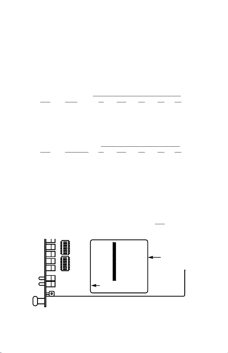
Prior to installation, you will need to examine the rear card you
have selected and make sure it is properly configured for your
application. Each rear card is configured by setting straps located on
the PC board. To configure the rear cards, you must set the
configuration straps. Figure 6 (below) shows the orientation of these
straps. Each strap can either be on pegs 1 and 2, or on pegs 2 and 3.
Sections 3.3.1 and 3.3.2 describe the strap locations and possible
settings for each rear card.
Figure 6. Orientation of interface card straps
23
Page 25

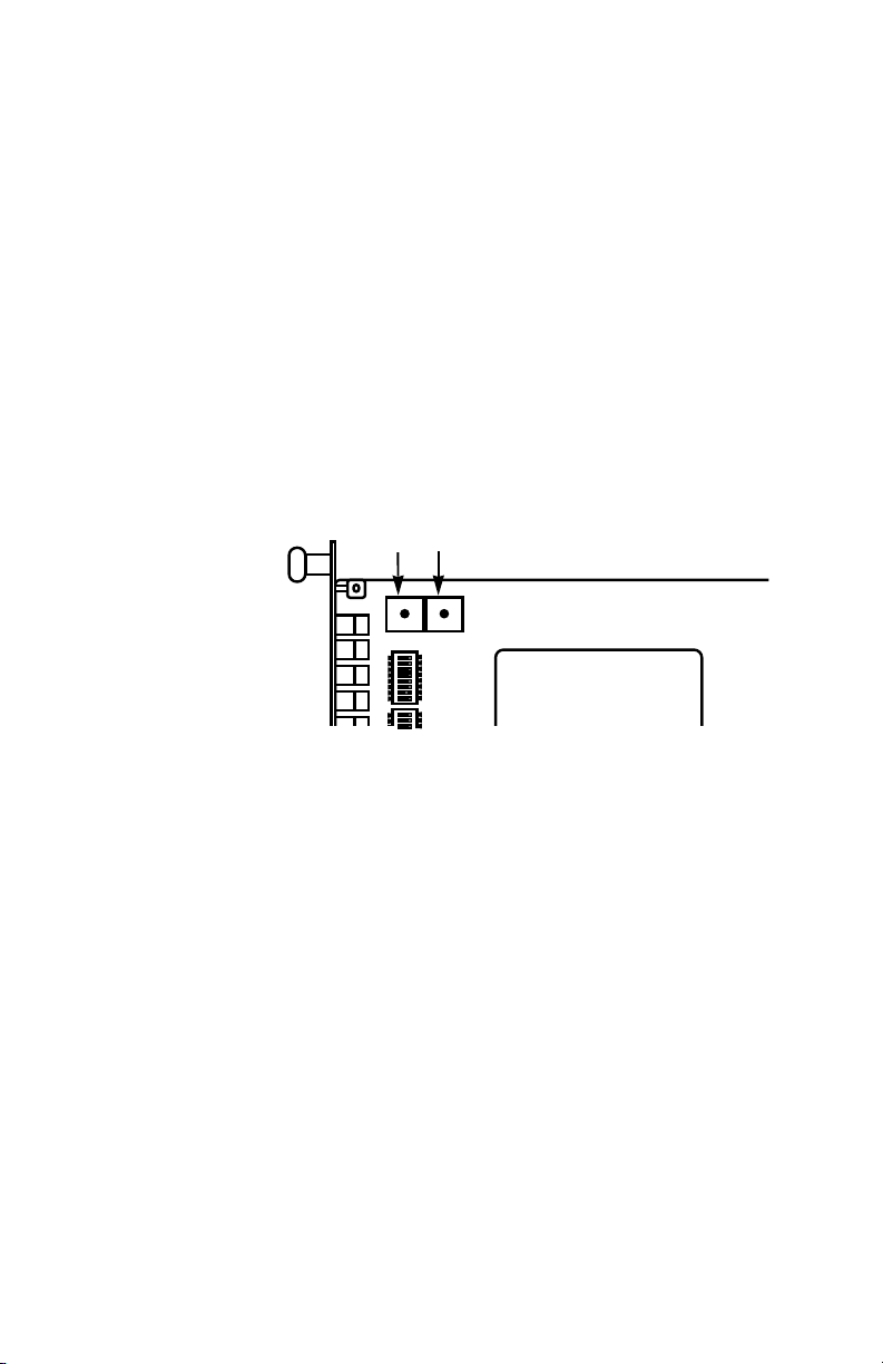
3.3.1 Model 1000RCM12548 Strap Settings
Figure 7 shows strap locations for the Model 1000RMC12548
(DB-25/RJ-48S) rear cards. These straps determine various grounding
characteristics for the terminal interface and twisted pair lines.
JB3
JB2
(NOT USED)
(peg 1 on top)
JB4
(peg 1 on left)
Figure 7. DB-25/RJ-48S strap locations
The table below provides an overview of interface strap functions
for the rear interface cards. Following this overview is a detailed
description of each strap’s function.
INTERFACE CARD STRAP SUMMARY TABLE #1
Strap Function Position 1&2 Position 2&3
JB3 DTE Shield (Pin1) & FRGND Connected Open*
JB4 FRGND & SGND Connected Open*
DTE Shield (Pin 1) & FRGND (JB3)
In the connected position, this strap links DB-25 pin 1 & frame
ground. In the open position, pin 1 is “lifted” from frame ground.
JB3
Position 1&2 = DTE Shield (Pin 1) and FRGND Connected
Position 2&3 = DTE Shield (Pin 1) and FRGND Not Connected
24
Page 26

SGND & FRGND (JB4)
In the connected position, this strap links DB-25 pin 7 (Signal
Ground) and frame ground. In the open position, pin 1 is “lifted” from
frame ground.
JB4
Position 1&2 = SGND (Pin 7) and FRGND Connected
Position 2&3 = SGND (Pin 7) and FRGND Not Connected
3.3.2 Model 1000RCM13448 Strap Settings
Figure 8 shows the strap location for the Model 1000RCM13448
(M/34/RJ-48S) rear card. This strap determines whether Signal Ground
and Frame Ground will be connected.
JB4
(peg 1 on left)
Figure 8. M/34/RJ-48 strap locations
SGND & FRGND (JB4)
In the connected position, this strap links Signal Ground and frame
ground.
JB4
Position 1&2 = SGND and FRGND Connected
Position 2&3 = SGND and FRGND Not Connected
25
Page 27

4.0 INSTALLATION
This section describes the functions of the Model 1000R16 rack
chassis, tells how to install front and rear Model 2500RC Series cards
into the chassis, and provides diagrams for wiring the interface
connections correctly.
4.1 THE MODEL 1000R16 RACK CHASSIS
The Model 1000R16 Rack Chassis (Figure 9, below) has sixteen
short range modem card slots, plus its own power supply. Measuring
only 3.5” high, the Model 1000R16 is designed to occupy only 2U in a
19” rack. Sturdy front handles allow the Model 1000R16 to be
extracted and transported conveniently.
Figure 9. Model 1000R16 Rack Chassis with power supply
4.1.1 The Rack Power Supply
The power supply included in the Model 1000R16 rack uses the
same mid-plane architecture as the modem cards. The front card of
the power supply slides in from the front, and the rear card slides in
from the rear. They plug into one another in the middle of the rack.
The front card is then secured by thumb screws and the rear card by
conventional metal screws.
WARNING! There are no user-serviceable parts in the
power supply section of the Model 2500RC Series.
Voltage setting changes and fuse replacement should only
be performed by qualified service personnel. Contact
Patton Electronics Technical support at (301)975-1007 for
more information.
(continued)
26
Page 28

Switching the Power Supply On and Off
The power switch is located on the front panel. When plugged in
and switched on, a red front panel LED will glow. Since the Model
1000R16 is a "hot swappable" rack,
be installed before switching on the power supply
may be switched off at any time without harming the installed cards.
it is not necessary for any cards to
. The power supply
NOTE: Please refer to the Model 1000RP Series User Manual
and DC Rack Mount Power Supplie
replacement information.
4.2 INSTALLING THE MODEL 2500RC SERIES INTO THE CHASSIS
The Model 2500RC Series is comprised of a front card and a rear
card. The two cards meet inside the rack chassis and plug into each
other by way of mating 50 pin card edge connectors. Use the following
steps as a guideline for installing each Model 2500RC Series into the
rack chassis:
1. Slide the rear card into the back of the chassis along the metal
rails provided.
2. Secure the rear card using the metal screws provided.
3. Slide the card into the front of the chassis. It should meet the
rear card when it’s almost all the way into the chassis.
4. Push the front card
rear card. It should “click” into place.
5. Secure the front card using the thumb screws.
NOTE: Since the Model 1000R16 chassis allows “hot
swapping” of cards, it is
when you install or remove a Model 2500RC Series.
gently
not necessary to power down
s for fuse and power card
into the card-edge receptacle of the
AC
the rack
4.3 WIRING THE MODEL 2500RC SERIES
Each of the rear interface cards compatible with the Model 2500RC
Series has one terminal interface port and one 4-wire (twisted pair)
port. For specific interface pin-outs, refer to the diagrams in
Appendix D of this manual.
27 28
Page 29

5.0 OPERATION
Once the Model 2500RC Series unit is installed and configured
properly it is ready to operate. This section describes the function of
the LED indicators, the status displays, the use of loopback test modes,
and Switched 56 dialing procedures (Models 2510RC and 2520RC
only).
5.1 LED DESCRIPTIONS
The Model 2500RC Series is equipped with nine LED indicators that
monitor the status of communication. Figure 12 (below) shows the
location of the LEDs on the Model 2500RC Series front panel. Note
also the location of the test mode switches and RS-232 control port
(used in Switched 56 dialing as well as software configuration).
Following Figure 12 is a description of each LED’s function.
• “TD” and “RD” will glow red to indicate an Idle condition or
Binary “1” data on the respective terminal interface signals.
Green indicates Binary “0” data.
Model 2500RC
DTR
CD
NS
TM
Remote
Power
TD
RD
CTS
OS
ER
Analog
511
511/E
Figure 10. The Model 2500RC Series' front panel LEDs
(continued)
Page 30

• “CTS” will glow green to indicate an On condition. When on,
the unit is ready to send data. If CTS remains off, check the
Forced RTS, Circuit Assurance and Anti-Stream settings.
• “CD” will glow green to indicate that a valid carrier is present.
If CD is not lit, there is no valid carrier signal detected.
• “DTR” will glow green to indicate that the DTR signal from the
terminal is active.
• “NS” will glow red to indicate No Signal. This means the
Model 2500RC Series receiver does not detect a signal from
the digital service provider (or, in the case of short-haul
operation, from the remote Model 2500RC Series). If NS is lit,
check for an unplugged cable, broken wire or an incorrect Line
Rate selection.
• “OS” glows red to indicate Out-of-Service. This means the
Model 2500RC Series has received an Out-of-Service signal
from the digital service provider and indicates a problem with
the service provider’s equipment. If this condition persists,
contact your service provider.
• “ER” glows red to indicate that an Error has been detected in
the received signal. ER will flash if the Model 2500RC Series
receives illegal bi-polar violations or framing errors. During the
511 or 511/E test, ER will flash to indicate that the Test Pattern
Detector has detected a bit error.
• “TM” glows red to indicate Test Mode. It will light if the unit is
placed into a test mode. The unit can be placed in test mode
by the local user, by the remote user or by the service
provider.
5.2 STATUS DISPLAYS
The Model 2500RC Series lets you use a VT-100 type RS-232
terminal to display the current configuration settings, as well as the
line/loop status.
Important: Please be sure you have read Section 3.2, and the Model
1000CC User Manual before attempting to implement the instructions
in the remainder of Section 5.2.
29 30
Page 31

5.2.1 Displaying Configuration Settings
To display the current settings of the hardware and /or software
switches, go to the Main Menu and select item 2, “Read Configuration”.
This will take you to the Read Configuration Menu (below).
In the Read Configuration Menu, you may select item 1 to read the
hardware switch configuration or item 2 to read the software switch
configuration. A sample screens is shown below:
(continued)
Page 32

5.2.2 Displaying Line/Loop Status
To check the current status of the Model 2500RC Series and the
associated circuit, go to the Main Menu and select item 4, “Display
Line/Loop Status”
1,2
. This will take you to a screen similar to the
Line/Loop Status Monitor Screen (below).
1
NOTE
: To refresh the display with the most up-to-date
information, key “4” and press [RETURN].
2
: The error count is reset after each time it is displayed.
NOTE
5.3 LOOPBACK TEST MODES
The Model 2500RC Series offers three loopback tests to evaluate
the condition of the CSU/DSUs and the communication link: local
analog loopback, remote digital loopback and telco loopback (C.O.
Loopback).
5.3.1 Local Analog Loopback (LAL)
The Local Analog Loopback (LAL) test checks the operation of the
local Model 2500RC Series. Any data sent to the local Model 2500RC
Series in this test mode will be echoed (returned) back to the user
device. For example, characters typed on the keyboard of a terminal
will appear on the terminal screen (see Figure 11, below).
CSU/DSU
Figure 11. Local analog loop
31 32
Page 33

LAL Test Activation
The LAL test may be activated in one of three ways:
1. Toggle the front panel “Local/Normal/Remote” switch to the
right hand side to the “Local” position.
2. Activate the LL lead from the DTE (Note: in order to use this
option, the DTE Loop Control option must be enabled–see
Section 3.2.4). If you are not sure which pin is the LL lead,
please refer to the pinout diagrams in Appendix D.
3 From a terminal, first go to the Main Menu and select item 3 to
display the Software Switch Menu (Section 3.2.4) In the
Software Switch Menu, select item “e” to go to the Local Line
Loop Menu (see below). To activate LAL, select item 1.
LAL Test Procedure
Once LAL is activated, the Model 2500RC Series transmit output is
connected to its own receiver. The “Test” LED should be lit. Follow
these steps to complete the test:
1. Verify that the data terminal equipment is operating properly
and can be used for a test. If a fault is indicated, call a
technician or replace the unit.
2. Perform a BER (bit error rate) test on each unit using a
separate BER tester (The Model 2500RC Series has a built-in
BER tester–see Section 5.4). If the BER test equipment
indicates no faults but the data terminal indicates a fault, follow
the manufacturer's checkout procedures for the data terminal.
Also, check the interface cable between the terminal and the
Model 2500RC Series.
Page 34

5.3.2 Remote Digital Loopback (RDL)
The Remote Digital Loopback (RDL) test checks the performance of
and
both the local and remote Model 2500RC Series',
the
communication link between them. Any characters sent to the remote
Model 2500RC Series in this test mode will be returned back to the
originating device. For example, characters typed on the keyboard of
the local terminal will appear on the local terminal screen
after
having
been passed to the remote Model 2500RC Series and looped back
(see Figure 12, below).
CSU/DSU
Digital Network
Figure 12. Remote digital loop
RDL Test Activation
The RDL test may be activated in one of three ways:
1) Toggle the front panel “Local/Normal/Remote” switch to the left
hand side to the “Remote” position.
2) Activate the RL lead from the DTE (Note: in order to use this
option, the DTE Loop Control option must be enabled–see
Section 3.2.4). If you are not sure which pin is the RL lead, please
refer to the pinout diagrams in Appendix D.
3) From a terminal, first go to the Main Menu and select item 3 to
display the Software Switch Menu (Section 3.2.4) In the
Software Switch Menu, select item “d” to go to the Set
Remote Digital Loop Menu (see below). To activate RDL, select
item 1.
33 34
Page 35

RDL Test Procedure
Once LAL is activated, the “Test” LED should be lit. Perform a BER
(bit error rate) test on the system, using BER testers on both ends. If
the BER test equipment indicates a fault and the Local Analog
Loopback test was successful for both Model 2500RC Series units, you
may have a problem with the line between the CSU/DSUs. You should
inspect the line for proper connections.
5.3.3 Telco Testing
The digital service provider’s central office can perform CSU Loop
and DSU Loop diagnostic testing. These diagnostics allow the central
office to evaluate circuit operation without making visits to a customer’s
premises.
CSU Loop
The CSU Loop is activated when the central office reverses the DC
sealing current that flows between the TX pair and the RX pair. In this
case, the Model 2500RC Series recognizes this and loops signals on
the RX pair back to the central office on the TX pair (see Figure 13,
below). While the CSU Loop is activated by the central office, the TM
light is illuminated.
CSUDSU Digital Network
Figure 13. CSU loop
DSU Loop
The DSU Loop is activated when the central office sends a DSU
loop signal over the twisted pair wire. The Model 2500RC Series
senses this signal and loops the digital data back to the central office
(see Figure 14, below). While the DSU Loop is activated, the TM light
is illuminated.
CSUDSU
Figure 14. DSU loop
Digital Network
Page 36

5.4 THE V.52 BER TEST PATTERN GENERATOR
The Model 2500RC Series has a built-in test pattern generator and
detector. It can be invoked at both ends of a link simultaneously (using
two operators) or it can be invoked in conjunction with the LAL or RDL
tests (using one operator). The following example requires two
operators–one to initiate and monitor the test at the local Model
2500RC Series, and one at the remote Model 2500RC Series. To use
the V.52 BER test by itself, both operators should
simultaneously
follow
these steps:
1. Locate the “511/511E” toggle switch on the front panel of the
Model 2500RC Series and move it to the left hand side (see
Note 1). This activates the V.52 BER test mode and transmits
a “511” pseudorandom test pattern to the other unit. If any
errors are received, the receiving CSU/DSU’s red “Error” LED
will blink sporadically (see Notes 1 & 2, below).
2. If the test indicates no errors are present, move the V.52
toggle switch to the right hand side, activating the “511/E” test
(see Note 2). The 511/E test transmits the 511 pseudorandom
test pattern and injects intentional errors about once per
second. If the test is working properly, the receiving
CSU/DSU’s red “Error” LED will blink
regularly
. A successful
“511/E” test will confirm that the link is in place, and that the
Model 2500RC Series’ built-in “511” generator and detector
are working properly.
1
NOTE
: The 511 BER pattern can also be activated using the
software control port. Follow these steps: From a terminal, first go
to the Main Menu and select item 3 to display the Software Switch
Menu (Section 3.2.4) In the Software Switch Menu, select item “c”
to go to the Send 511 Pattern Menu (see below). To send a 511
pattern, select item 1.
2
: Control Port activation of the “511E” pattern is not
NOTE
possible. The “511E” pattern may only be activated using the front
panel toggle switch.
35 36
Page 37

5.5 SWITCHED 56 DIALING COMMANDS (MODELS 2510RC &
2520RC)
CAUTION! For proper Switched 56 operation, you must enable
the Circuit Assurance and Force RTS options as described in
Section 4.0. Failure to do so may prevent the Model 2500RC
Series unit from answering incoming Switched 56 calls.
To access the Switched 56 dialing capabilities of the Mode 2500RC
Series, go to the Main Menu (see Section 3.2.4) and select item 5, “Set
Switched 56 Dialing Parameters”. This will take you to the Switched 56
Menu (see below). The following paragraphs describe the commands
in the Switched 56 Menu.
Store Phone Number (Enable DTR Dialing)
Selecting item 1 in the Dial Menu lets you activate the Model
2500RC Series’ “DTR Dialing” feature by storing a phone number in the
unit’s non-volatile memory. The Model 2500RC Series automatically
dials this number when the DTE raises the DTR lead. When you issue
this command, the Model 2500RC Series responds with this prompt:
Enter up to 12 digits (without hyphens or other alphabetic characters),
followed by [RETURN]. For example: “13015551212.”
CAUTION! Pressing [RETURN] by itself will erase any
previously stored number from the unit’s non-volatile memory
and cannot be undone. This will also disable DTR dialing.
NOTE: To disable DTR dialing, press [RETURN] (and nothing
else) when asked to enter the number to be stored.
Page 38

Read Stored Number
Selecting item 2 in the Dial Menu lets you view the phone number
currently stored in the Model 2500RC Series non-volatile memory.
Dial New Number
Selecting item 3 in the Dial Menu lets you dial a number other than
the one stored in non-volatile memory. When you select this menu
item, the Model 2500RC Series responds with this prompt:
Enter up to 12 digits (without hyphens or other alphabetic characters),
followed by [RETURN]. For example: “13015551212.”
After dialing the number, the Model 2500RC Series will display the
message, “Dialing” and then display each number as it is dialed. The
Model 2500RC Series will then prompt the user to wait while the
connection is made. One of the following messages will then be
displayed to indicate the success or failure or the connection:
• CONNECT: The called unit has answered.
• NO WINK: The central office did not send a wink signal
within 5 seconds of line seizure.
• SHORT WINK: A wink signal less than 120 milliseconds
was received.
• LONG WINK: A wink signal greater than 320 milliseconds
was received.
• NO CARRIER: The called unit did not answer within 30
seconds.
• DTR OFF: DTR must be on to dial.
• OFF HOOK: The Model 2500RC Series is already off-hook
and in data mode.
NOTE: The control port will not respond to additional commands
until one of the above response messages is issued.
Hang Up
Selecting item 4 in the Dial Menu terminates the call.
37
Page 39

APPENDIX A
SPECIFICATIONS
DDS Type: Dedicated
Transmission Format: Asynchronous, synchronous
Interface: RS-232 and V.35
Standards: AT&T 62310 compliant
DDS Line Rates: 2.4, 4.8, 9.6, 19.2, 56 and 64 Kbps
DTE Rates: 2.4, 4.8, 9.6, 19.2, 38.4, 56, and 64
Kbps; 57.6 Kbps, async, 2 stop bits
Control Port: Configuration and diagnostics
Transmission Line: 4-wire
Applications: DDS point-to-point or multipoint;
campus-area point-to-point
Indicators: LED indicators for TD, RD, CTS, CD,
DTR, No Signal, Out-of-Service, Error
and Test Mode
Diagnostics: V.54 compliant local and remote
loopback tests; V.52 compliant
511/511E BER test, TELCO CSU and
DSU loops
Connectors: DB-25 and M/34
Power Supply: 115V or 230V AC
Dimensions: 7.3” x 6.6” x 1.6”
Model 2500RC Series Distance Table (miles)
Data
Rate
64 Kbps 7.1 4.9 3.4
56 Kbps 7.6 5.2 3.6
19.2 Kbps 8.7 6.2 4.5
9600 bps 10.4 7.7 5.8
4800 bps 13.7 10.6 9.7
2400 bps 15.1 14.2 9.1
Wire Gauge
22 24 26
38
Page 40

APPENDIX B
CABLE RECOMMENDATIONS
The Patton Model 2500RC Series operates at frequencies of 20kHz
or less and has been performance tested by Patton technicians using
twisted-pair cable with the following characteristics:
W
ire Gauge Capacitance Resistance
19 AWG 83nf/mi or 15.72 pf/ft. .0163 Ohms/ft.
22 AWG 83nf/mi or 15.72 pf/ft. .0326 Ohms/ft.
24 AWG 83nf/mi or 15.72 pf/ft. .05165 Ohms/ft.
To gain optimum performance from the Model 2500RC Series,
please keep the following guidelines in mind:
•
Always
use twisted pair wire—this is not an option.
• Use twisted pair wire with a capacitance of 20pf/ft or less.
• Avoid twisted pair wire thinner than 26 AWG (i.e. avoid higher
AWG numbers than 26)
• Use of twisted pair with a resistance greater than the above
specifications may cause a reduction in maximum distance
obtainable. Functionality should not be affected.
• Many environmental factors can affect the maximum distances
obtainable at a particular site. Use the above data rate/distance
table as a
general guideline only.
39
Page 41

APPENDIX C
FACTORY REPLACEMENT PARTS
AND ACCESSORIES
Patton Model #
10-2500RC......................DDS Cable, RJ48 - RJ48, 6 foot
10-561S...........................Control Port Cable, EIA-561, 6ft, shielded
12M-561 ..........................Adapter, EIA-561 to DB-25 Male
12F-561...........................Adapter, EIA-561 to DB-25 Female
082R2..............................Fuse 5x20mm, 200mA, 250V, Time-lag
Description
Little Fuse P/N 239.200
1000RPEM......................120/240V Rear Power Entry Module
1000RPSM-2 ..................120/240V Front Power Supply Module
1000RPEM-DC................DC Rear Power Entry Module
1000RPSM-48A ..............48V Front Power Supply Module
1000RPEM-V ..................120/240V CE Compliant Rear Power
Entry Module
1000RPSM-V ..................120/240V CE Compliant Front Power
Supply Module
0805US ...........................American Power Cord
0805EUR.........................European Power Cord CEE 7
0805UK ...........................United Kingdom Power Cord
0805AUS.........................Australia/New Zealand Power Cord
0805DEN.........................Denmark Power Cord
0805FR............................France/Belgium Power Cord
0805IN.............................India Power Cord
0805IS.............................Israel Power Cord
0805JAP..........................Japan Power Cord
0805SW...........................Switzerland Power Cord
40
Page 42

APPENDIX D
INTERFACE PIN ASSIGNMENT
DDS INTERFACE
The DDS Interface is an RJ-48S modular jack.
Pin #
Signal
1TX+
2TX3 no connection
4 no connection
5 no connection
6 no connection
7RX+
8RX-
M/34 CONNECTOR, TERMINAL INTERFACE
Pin #
Signal
B SGND (Signal Ground)
CRTS
DCTS
EDSR
FCD
HDTR
L LL (Local Loop)
M TM (Test Mode)
N RL (Remote Loop)
PTD
RRD
STD/
T RD/
UXTC
VRC
WXTC/
X RC/
YTC
AA TC/
41
Page 43

(APPENDIX D - Continued)
DB-25 CONNECTOR, TERMINAL INTERFACE
Pin #
Signal
1 Frame Ground
2TD
3RD
4RTS
5CTS
6DSR
7 SGND (Signal Ground)
8CD
15 TC
17 RC
18 LL (Local Loop)
20 DTR
21 RL (Remote Loop)
24 XTC
25 TM (Test Mode)
CONTROL PORT INTERFACE
8 Position modular connector compliant with EIA-561.
Pin #
Signal
4 Signal Ground
5 RD (Output)
6 TD (Input)
42
Page 44

APPENDIX E
TRANSMITTER CLOCK SOURCE DURING TEST LOOPS
Analog Originating Receiving
Clock Mode Normal Loop Remote Loop Remote Loop
Internal INT INT INT RC
External EXT INT EXT EXT
Network RC INT RC RC
RC = Received Clock
Copyright ©
Patton Electronics Company
All Rights Reserved
43
Page 45

Page 46

Page 47

Page 48

Dear Valued Customer,
Thank you for purchasing Patton Electronics products! We do
appreciate your business. I trust that you find this user manual helpful.
We manufacture one of the widest selections of data communications
products in the world including CSU/DSU's, network termination units,
powered and self-powered short range modems, fiber optic modems, interface
converters, baluns, electronic data switches, data-line surge protectors,
multiplexers, transceivers, hubs, print servers and much more. We produce
these products at our Gaithersburg, MD, USA facility, and can custom
manufacture products for your unique needs.
We would like to hear from you. Please contact us in any of the
following ways to tell us how you like this product and how we can meet your
product needs today and in the future.
Web: http://www.patton.com
Sales E-mail: sales@patton.com
Support E-mail: support@patton.com
Phone - Sales (301) 975-1000
Phone - Support (301) 975-1007
Fax: (301) 869-9293
Mail: Patton Electronics Company
7622 Rickenbacker Drive
Gaithersburg, MD 20879 USA
We are committed to a quality product at a quality price. Patton
Electronics is ISO 9001 certified. We meet and exceed the highest
standards in the industry (CE, UL, etc.).
It is our business to serve you. If you are not satisfied with any
aspect of this product or the service provided from Patton Electronics or its
distributors, please let us know.
Thank you.
Burton A.Patton
Vice President
P.S. Please tell us where you purchased this product.
_________________________________________________________
 Loading...