

Patton 2400 USER MANUAL
USER
MANUAL
MODEL 2400
56/64 Kbps, 4-Wire DDS
and Clear Channel CSU/DSU
CERTIFIED
An ISO-9001
Certified Company
Part# 07M2400-B
Doc# 099041UB
Revised 7/16/97
SALES OFFICE
(301) 975-1000
TECHNICAL SUPPORT
(301) 975-1007
http://www.patton.com

1.0 WARRANTY INFORMATION
Patton Electronics warrants all Model 2400 components to be
free from defects, and will—at our option—repair or replace the product
should it fail within one year from the first date of shipment.
This warranty is limited to defects in workmanship or materials, and
does not cover customer damage, abuse or unauthorized modification.
If this product fails or does not perform as warranted, your sole
recourse shall be repair or replacement as described above. Under no
condition shall Patton Electronics be liable for any damages incurred
by the use of this product. These damages include, but are not limited
to, the following: lost profits, lost savings and incidental or
consequential damages arising from the use of or inability to use this
product. Patton Electronics specifically disclaims all other warranties,
expressed or implied, and the installation or use of this product shall be
deemed an acceptance of these terms by the user.
Your telephone company may make changes in its facilities,
equipment, operations or procedures that could affect the proper
operation of the Model 2400 Series. If this happens, the telephone
company should give you advance notice to prevent the interruption of
your service.
The telephone company may decide to temporarily discontinue
your service if they believe your Model 2400 Series may cause harm to
the telephone network. Whenever possible, they will contact you in
advance. If you elect to do so, you have the right to file a complaint
with the FCC. The telephone company may ask you to disconnect the
equipment from the telephone network until the problem has been
corrected or until you are certain that the Model 2400 Series is not
malfunctioning.
The following information may be required when applying to your
local telephone company for leased line facilities.
1.1 RADIO AND TV INTERFERENCE
The Model 2400 generates and uses radio frequency energy, and if
not installed and used properly—that is, in strict accordance with the
manufacturer's instructions—may cause interference to radio and
television reception. The Model 2400 has been tested and found to
comply with the limits for a Class A computing device in accordance
with the specifications in Subpart J of Part 15 of FCC rules, which are
designed to provide reasonable protection from such interference in a
commercial installation. However, there is no guarantee that
interference will not occur in a particular installation. If the Model 2400
does cause interference to radio or television reception, which can be
determined by disconnecting the RS-232 interface, the user is
encouraged to try to correct the interference by one or more of the
following measures: moving the computing equipment away from the
receiver, re-orienting the receiving antenna and/or plugging the
receiving equipment into a different AC outlet (such that the computing
equipment and receiver are on different branches). In the event the
user detects intermittent or continuous product malfunction due to
nearby high power transmitting radio frequency equipment, the user is
strongly advised to only use data cables with an external outer shield
bonded to a metal or metalized connector.
1.2 FCC INFORMATION
The Model 2400 Series has been tested and registered in
compliance with the specifications in Part 68 of the FCC rules. A label
on the equipment bears the FCC registration number. You may be
requested to provide this information to your telephone company.
Service Digital Facility Service Order Network
Type Interface Code Code Jacks
56 Kbps 04DU5-56 6.0F RJ48S
64 Kbps 04DU5-64 6.0F RJ48S
1.3 CE NOTICE
The CE symbol on your Patton Electronics equipment indicates
that it is in compliance with the Electromagnetic Compatibility (EMC)
directive and the Low Voltage Directive (LVD) of the Union European
(EU). A Certificate of Compliance is available by contacting Patton
Technical Support.
1.4 SERVICE INFORMATION
All warranty and non-warranty repairs must be returned freight
prepaid and insured to Patton Electronics. All returns must have a
Return Materials Authorization number on the outside of the shipping
container. This number may be obtained from Patton Electronics
Technical Support: (301) 975-1007; http://www.patton.com; or,
support@patton.com. Notice:
number will not be accepted
Patton Electronics' technical staff is also available to answer any
questions that might arise concerning the installation or use of your
Model 2400. Technical Service hours: 8AM to 5PM EST, Monday
through Friday.
Packages received without an RMA
.
2.0 GENERAL INFORMATION
3.0 CONFIGURATION
Thank you for your purchase of this Patton Electronics product.
This product has been thoroughly inspected and tested and is
warranted for One Year parts and labor. If any questions arise during
installation or use of the 2400, contact Patton Electronics Technical
Support at (301) 975-1000.
2.1 FEATURES
• Synchronous data rates of 56 or 64 Kbps
• Full duplex communication over two dedicated twisted pairs
• Supports distances to 3.4 miles (5.5 km) over 26 AWG
(.4 mm)wire
• Selectable internal, external, network receive recover, or
campus clock options
• Built-in V.54 loopback tests and V.52 BER test patterns
• Works with 56 Kbps DDS, 64 Kbps Clear Channel, or private
twisted pair circuits
• Switchable Circuit Assurance feature
• Seven front panel LEDs monitor power, communication and test
status
• RJ-48S jack provided for line connection
• RS-232 version has a DB-25 connector
• V.35 version has an M/34 connector
• Ultra-compact enclosure fits in tight spaces
The Model 2400 is easy to install and is ruggedly designed for
excellent reliability. The following instructions will help you set up and
install the Model 2400 properly.
Both versions of the Model 2400 use a mini DIP switch package
and jumper strap that allow configuration to a wide range of
applications. To configure the Model 2400 for use in your application,
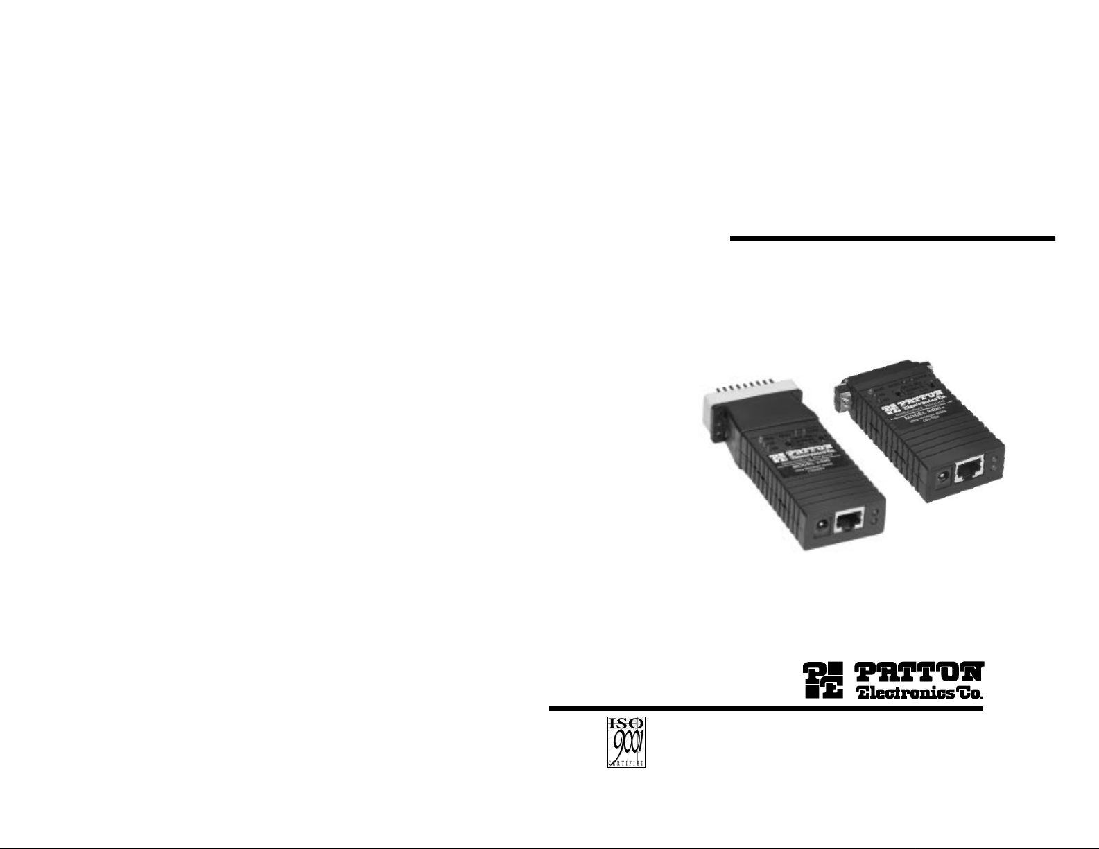
you must first configure the unit. To do so, first open the case by
inserting a flat head screw driver into an open slot on either side of the
case, as in Figure 1.
Figure 1. How to Use a Small Flathead Screwdriver to Begin to Open the Model 2400 Case
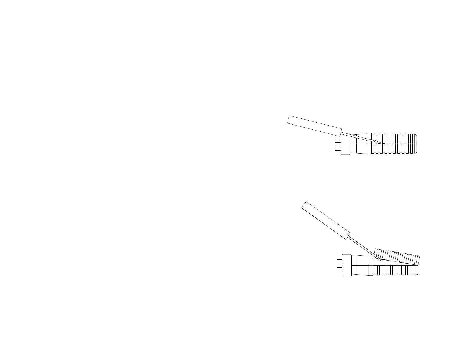
Twist the screw driver head slightly and the top half of the case will
separate from the lower half, as in Figure 2. You now have access to
the internal switches used to configure the unit.
2.2 DESCRIPTION
The Model 2400 DDS & Clear Channel CSU/DSU is a miniature
CSU/DSU that is designed for 56 kbps or 64 kbps Clear Channel
communications over a synchronous DDS circuit -- or over dedicated
twisted pair. The Model 2400 also supports distances up to 3.4 miles
(5.5 km) over a dedicated twisted pair circuit.
The Model 2400 provides switch selectable timing options of
internal, external, and network receive-recovered clock. Connecting
directly to the RS-232/V.24 (Model 2400/A) or V.35 (Model 2400/C)
port, the ultra-compact Model 2400 attaches without using additional
cables.
The Model 2400’s built-in V.54 loopback test modes and V.52 BER
test patterns are accessed using two front panel switches. Seven LEDs
monitor power, test modes and communication status. Twisted-pair line
connections are facilitated by a modular RJ-48S jack on the rear of the
unit.
Figure 2.
How to Use a Small Flathead Screwdriver to Finish Opening the Model 2400 Case
After opening the case, please refer to Sections 3.1 and 3.2 to set
the configuration switches and jumpers.
To close the case, fit the 2 halves together snugly and snap them
back in place.

3.1 CONFIGURATION SWITCH SET ‘S1’
The Model 2400 uses a set of eight internal switches to set
clocking mode, circuit assurance, RTS control, data rate and loop
control. Figures 3 (Model 2400/A) and 4 (Model 2400/C) show the
switch and jumper locations with respect to the other components on
bottom side the PC board.
Switch S1
Figure 3. Position of the DIP Switches on the 2400/A PC board
ON
12345678
SWITCH SET 1 SUMMARY TABLE
Position Function Factory Default
S1-1 Clock Mode Off
Network
S1-2 Clock Mode On
}
S1-3 Circuit Assurance Off Disabled
S1-4 RTS On Forced On
S1-5 Data Rate Off 56 Kbps
S1-6 Front Panel Switch Off Enable Front Panel
Control Switches
S1-7 DTE Loop Control On Loop Control
From DTE Disabled
S1-8 Receive RDL Off Receive RDL
Enabled
Switches S1-1 and S1-2: Clock Mode
The setting for switches S1-1 and S1-2 determines the transmitter
clocking mode for the Model 2400.
12345678
Switch S1
Figure 4. Position of the DIP Switches on the Model 2400/CM PC board
ON
Figure 5 (below) shows a close-up of DIP Switch S1 with respect to
ON and OFF positions. Default switch settings are shown in the table
on the following page. Descriptions of each switch follow the table.
ON
12345678
Figure 5. Close-up of DIP Switches Showing “ON” and “OFF” Positions
ON
OFF
S1-1
S1-2 Clock Mode Description
On Off External (DTE) Transmit clock derived
from terminal interface
Off On Network (Looped) Transmit clock derived
from the received line
signal; Use this mode
for Dedicated DDS
operation
Off Off Internal (Master) Transmit clock derived
internally
On On Campus Clock Transmit clock derived
from received line signal.
Allows remote
device (in
campus clock mode) to
initiate V.54 loopback. For
use only in campus shorthaul configuration (Note:
Opposite device must be
in internal clock mode).
 Loading...