

Page 1
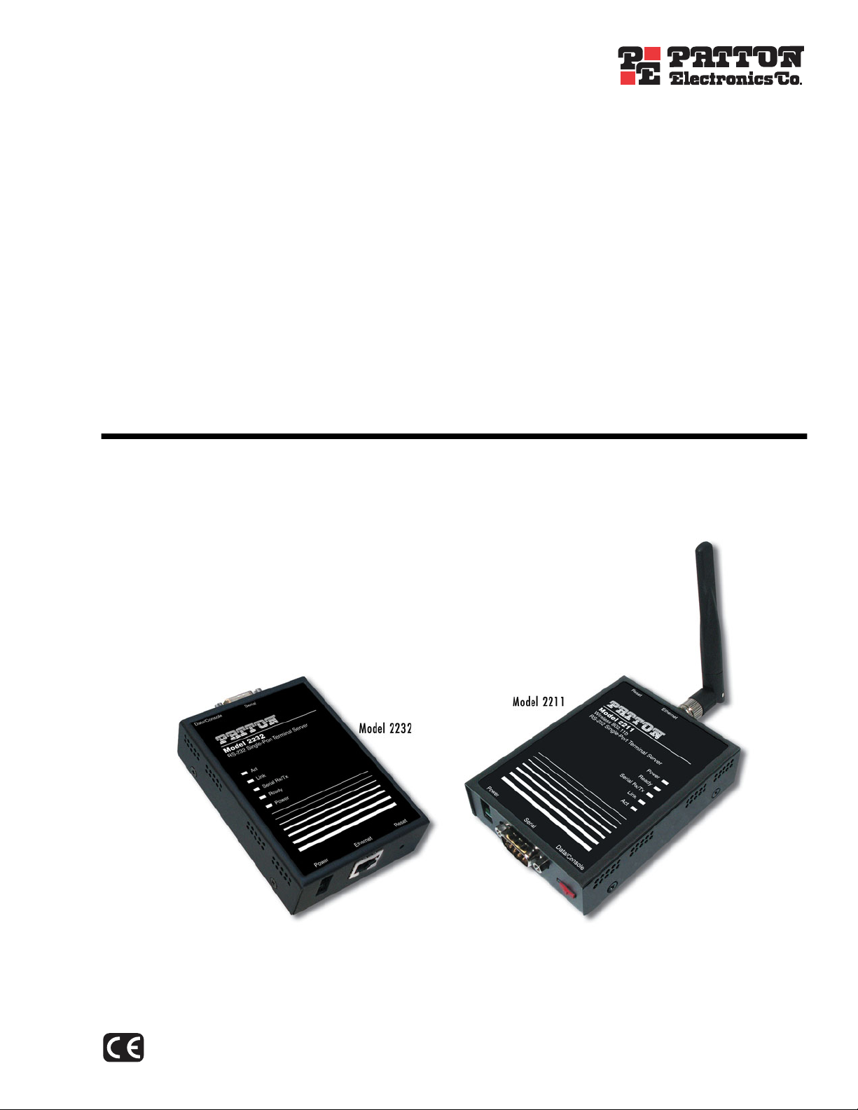
Model 2211
EtherBITS™ Wireless 802.11b
RS-232 Single-Port Device Server
Model 2232
EtherBITS™ RS-232 Single-Port
Device Server
Getting Started Guide
Sales Office: +1 (301) 975-1000
Technical Support: +1 (301) 975-1007
E-mail: support@patton.com
WWW: www.patton.com
Document Number: 08311U1-001 Rev. A
Part Number: 07M2232-GS
Revised: May 12, 2006
Page 2

Patton Electronics Company, Inc.
7622 Rickenbacker Drive
Gaithersburg, MD 20879 USA
Tel: +1 (301) 975-1000
Fax: +1 (301) 869-9293
Support: +1 (301) 975-1007
Web: www.patton.com
E-mail: support@patton.com
Trademark Statement
EtherBITS is a trademark of Patton Electronics Co..
Copyright © 2006, Patton Electronics Company. All rights reserved.
The information in this document is subject to change without notice. Patton Elec-
tronics assumes no liability for errors that may appear in this document.
Warranty Information
The software described in this document is furnished under a license and may be used
or copied only in accordance with the terms of such license.
Patton Electronics warrants all EtherBITS™ components to be free from defects, and
will—at our option—repair or replace the product should it fail within one year from
the first date of the shipment.
This warranty is limited to defects in workmanship or materials, and does not cover
customer damage, abuse or unauthorized modification. If the product fails to perform
as warranted, your sole recourse shall be repair or replacement as described above.
Under no condition shall Patton Electronics be liable for any damages incurred by the
use of this product. These damages include, but are not limited to, the following: lost
profits, lost savings and incidental or consequential damages arising from the use of or
inability to use this product. Patton Electronics specifically disclaims all other warran-
ties, expressed or implied, and the installation or use of this product shall be deemed
an acceptance of these terms by the user.
Note
Conformity documents of all Patton products can be viewed online at
www.patton.com under the appropriate product page.
Page 3

Summary Table of Contents
1 Overview ....................................................................................................................................................... 13
2 Getting started............................................................................................................................................... 17
3 Wireless LAN configuration (Model 2211 only) ........................................................................................... 30
4 IP address configuration ............................................................................................................................... 34
5 Host Mode configuration.............................................................................................................................. 39
6 Serial port configuration ............................................................................................................................... 50
7 System administration................................................................................................................................... 53
8 Contacting Patton for assistance ................................................................................................................... 55
A Compliance information .............................................................................................................................. 58
B Specifications ................................................................................................................................................ 60
C Cable Recommendations .............................................................................................................................. 64
D Well-known port numbers ........................................................................................................................... 68
E Troubleshooting ........................................................................................................................................... 70
3
Page 4

Contents
Summary Table of Contents ........................................................................................................................... 3
Contents ......................................................................................................................................................... 4
List of Figures ................................................................................................................................................. 7
List of Tables .................................................................................................................................................. 8
About this guide ............................................................................................................................................. 9
Audience................................................................................................................................................................. 9
Structure................................................................................................................................................................. 9
Precautions ........................................................................................................................................................... 10
Safety when working with electricity ...............................................................................................................10
General observations .......................................................................................................................................11
Factory default parameters.................................................................................................................................... 11
Typographical conventions used in this document................................................................................................ 12
General conventions .......................................................................................................................................12
1 Overview ....................................................................................................................................................... 13
Introduction..........................................................................................................................................................14
Glossary.................................................................................................................................................................15
MAC address ..................................................................................................................................................15
Host ................................................................................................................................................................15
Session ............................................................................................................................................................15
Client/Server ...................................................................................................................................................15
Acronyms ..............................................................................................................................................................16
2 Getting started............................................................................................................................................... 17
Introduction..........................................................................................................................................................18
Unpacking the device server ..................................................................................................................................18
Controls, ports, and indicators...............................................................................................................................19
Connecting the hardware.......................................................................................................................................20
Connecting power ...........................................................................................................................................20
Connecting the device server to the network ...................................................................................................21
Connecting the Ethernet cable (Model 2232 only) ....................................................................................21
Connecting to the wireless LAN (Model 2211 only) .................................................................................21
Connecting to the serial device ........................................................................................................................22
Accessing the Console Port....................................................................................................................................22
Using the System console ................................................................................................................................22
Using remote console ......................................................................................................................................23
Command usage....................................................................................................................................................25
'set' Command ..........................................................................................................................................26
'get' Command .........................................................................................................................................27
'help' Command .......................................................................................................................................28
'factorydefault' Command .........................................................................................................................29
'save' Command ........................................................................................................................................29
4
Page 5

5
Models 2211 & 2232 Getting Started Guide
'exit' Command ........................................................................................................................................29
'reboot' Command ....................................................................................................................................29
3 Wireless LAN configuration (Model 2211 only) ........................................................................................... 30
Introduction..........................................................................................................................................................31
Infrastructure Mode and Ad-hoc Mode ..........................................................................................................31
Network Name: SSID (Service Set Identifier) .................................................................................................31
Channel ..........................................................................................................................................................31
Security ...........................................................................................................................................................31
Settings..................................................................................................................................................................32
SSID ...............................................................................................................................................................32
WEP1 .............................................................................................................................................................32
WEP2 .............................................................................................................................................................33
WEP Key ........................................................................................................................................................33
4 IP address configuration ............................................................................................................................... 34
Introduction..........................................................................................................................................................35
Static IP.................................................................................................................................................................35
Static IP configuration ....................................................................................................................................36
DHCP...................................................................................................................................................................36
DHCP Configuration .....................................................................................................................................37
IP Filtering ............................................................................................................................................................37
5 Host Mode configuration.............................................................................................................................. 39
Introduction..........................................................................................................................................................40
TCP Server Mode Operations ...............................................................................................................................42
TCP Server Mode Configuration ....................................................................................................................43
TCP Client Mode Operations...............................................................................................................................44
TCP Client Mode Configuration ....................................................................................................................46
TCP Server/Client Mode Operations ....................................................................................................................47
TCP Server/Client Mode Configuration .........................................................................................................49
6 Serial port configuration ............................................................................................................................... 50
Introduction..........................................................................................................................................................51
7 System administration................................................................................................................................... 53
Introduction..........................................................................................................................................................54
8 Contacting Patton for assistance ................................................................................................................... 55
Introduction..........................................................................................................................................................56
Contact information..............................................................................................................................................56
Patton support headquarters in the USA .........................................................................................................56
Alternate Patton support for Europe, Middle East, and Africa (EMEA) ..........................................................56
Warranty Service and Returned Merchandise Authorizations (RMAs)...................................................................56
Warranty coverage ..........................................................................................................................................56
Out-of-warranty service .............................................................................................................................57
Returns for credit ......................................................................................................................................57
Return for credit policy .............................................................................................................................57
Page 6

6
Models 2211 & 2232 Getting Started Guide
RMA numbers ................................................................................................................................................57
Shipping instructions ................................................................................................................................57
A Compliance information .............................................................................................................................. 58
Compliance ...........................................................................................................................................................59
Model 2211 ....................................................................................................................................................59
Model 2232 ....................................................................................................................................................59
Radio and TV Interference (FCC Part 15) ............................................................................................................59
CE Declaration of Conformity ..............................................................................................................................59
B Specifications ................................................................................................................................................ 60
Serial interface .......................................................................................................................................................61
Network interface..................................................................................................................................................61
Model 2211 ....................................................................................................................................................61
Model 2232 ....................................................................................................................................................61
Protocols ...............................................................................................................................................................62
Model 2211 ....................................................................................................................................................62
Model 2232 ....................................................................................................................................................62
Security .................................................................................................................................................................62
Management .........................................................................................................................................................62
Diagnostic LEDs ...................................................................................................................................................62
Environmental.......................................................................................................................................................62
Physical .................................................................................................................................................................62
Model 2211 ....................................................................................................................................................62
Model 2232 ....................................................................................................................................................62
Power ....................................................................................................................................................................63
Model 2211 ....................................................................................................................................................63
Model 2232 ....................................................................................................................................................63
C Cable Recommendations .............................................................................................................................. 64
Ethernet pin-outs (Model 2232 only)....................................................................................................................65
Serial port pin-outs................................................................................................................................................66
Ethernet wiring diagrams (Model 2232 only) ........................................................................................................66
Serial wiring diagram.............................................................................................................................................67
D Well-known port numbers ........................................................................................................................... 68
Introduction..........................................................................................................................................................69
E Troubleshooting ........................................................................................................................................... 70
Power/LED Status Troubleshooting......................................................................................................................71
Serial Console Troubleshooting.............................................................................................................................71
Remote Console Troubleshooting .........................................................................................................................72
IP Address Troubleshooting ..................................................................................................................................72
DHCP Troubleshooting........................................................................................................................................72
TCP Server Mode Operation Troubleshooting......................................................................................................73
Serial Communication Troubleshooting................................................................................................................73
Page 7

List of Figures
1 Model 2211 EtherBITS device server . . . . . . . . . . . . . . . . . . . . . . . . . . . . . . . . . . . . . . . . . . . . . . . . . . . . . . . . 14
2 Model 2232 EtherBITS device server . . . . . . . . . . . . . . . . . . . . . . . . . . . . . . . . . . . . . . . . . . . . . . . . . . . . . . . . 14
3 Device server LEDs, switches, and ports . . . . . . . . . . . . . . . . . . . . . . . . . . . . . . . . . . . . . . . . . . . . . . . . . . . . . . 19
4 Factory Reset button location . . . . . . . . . . . . . . . . . . . . . . . . . . . . . . . . . . . . . . . . . . . . . . . . . . . . . . . . . . . . . . 20
5 Telnet program set up example (TeraTerm Pro) . . . . . . . . . . . . . . . . . . . . . . . . . . . . . . . . . . . . . . . . . . . . . . . . 24
6 State Transition Diagram of TCP server mode . . . . . . . . . . . . . . . . . . . . . . . . . . . . . . . . . . . . . . . . . . . . . . . . . 43
7 State Transition Diagram of TCP client mode . . . . . . . . . . . . . . . . . . . . . . . . . . . . . . . . . . . . . . . . . . . . . . . . . 46
8 State Transition Diagram of TCP server/client mode . . . . . . . . . . . . . . . . . . . . . . . . . . . . . . . . . . . . . . . . . . . . 48
9 Pin layout of the RJ45 connector . . . . . . . . . . . . . . . . . . . . . . . . . . . . . . . . . . . . . . . . . . . . . . . . . . . . . . . . . . . 65
10 Pin layout of the DB-9 connector . . . . . . . . . . . . . . . . . . . . . . . . . . . . . . . . . . . . . . . . . . . . . . . . . . . . . . . . . . . 66
11 Ethernet direct connection using crossover Ethernet cable . . . . . . . . . . . . . . . . . . . . . . . . . . . . . . . . . . . . . . . . 66
12 Ethernet connection using straight through Ethernet cable . . . . . . . . . . . . . . . . . . . . . . . . . . . . . . . . . . . . . . . . 67
13 RS-232 wiring diagram . . . . . . . . . . . . . . . . . . . . . . . . . . . . . . . . . . . . . . . . . . . . . . . . . . . . . . . . . . . . . . . . . . . 67
7
Page 8

List of Tables
1 General conventions . . . . . . . . . . . . . . . . . . . . . . . . . . . . . . . . . . . . . . . . . . . . . . . . . . . . . . . . . . . . . . . . . . . . . 12
2 Device server LEDs . . . . . . . . . . . . . . . . . . . . . . . . . . . . . . . . . . . . . . . . . . . . . . . . . . . . . . . . . . . . . . . . . . . . . . 19
3 Device server command set summary . . . . . . . . . . . . . . . . . . . . . . . . . . . . . . . . . . . . . . . . . . . . . . . . . . . . . . . . 25
4 Wireless LAN setting parameters . . . . . . . . . . . . . . . . . . . . . . . . . . . . . . . . . . . . . . . . . . . . . . . . . . . . . . . . . . . 32
5 IP configuration parameters . . . . . . . . . . . . . . . . . . . . . . . . . . . . . . . . . . . . . . . . . . . . . . . . . . . . . . . . . . . . . . . 35
6 Input examples of allowed remote hosts . . . . . . . . . . . . . . . . . . . . . . . . . . . . . . . . . . . . . . . . . . . . . . . . . . . . . . 37
7 Device server TCP/IP session modes . . . . . . . . . . . . . . . . . . . . . . . . . . . . . . . . . . . . . . . . . . . . . . . . . . . . . . . . . 40
8 Host mode configuration parameters . . . . . . . . . . . . . . . . . . . . . . . . . . . . . . . . . . . . . . . . . . . . . . . . . . . . . . . . 40
9 Serial Port Configuration parameters . . . . . . . . . . . . . . . . . . . . . . . . . . . . . . . . . . . . . . . . . . . . . . . . . . . . . . . . 51
10 Pin assignment of the RJ45 connector for Ethernet . . . . . . . . . . . . . . . . . . . . . . . . . . . . . . . . . . . . . . . . . . . . . 65
11 Pin assignment of DB-9 connector . . . . . . . . . . . . . . . . . . . . . . . . . . . . . . . . . . . . . . . . . . . . . . . . . . . . . . . . . . 66
12 Well-known port numbers . . . . . . . . . . . . . . . . . . . . . . . . . . . . . . . . . . . . . . . . . . . . . . . . . . . . . . . . . . . . . . . . 69
8
Page 9

About this guide
This guide describes installing and configuring a Patton Electronics Model 2211 EtherBITS™ Wireless
802.11b RS-232 Single-Port Device Server or Model 2232 EtherBITS RS-232 Single-Port Device Server. By
the time you are finished with this guide, your device server will be fully connected and able to transfer data.
Audience
This guide is intended for the following users:
Operators
Installers
Maintenance technicians
Structure
This guide contains the following chapters and appendices:
Chapter 1 on page 13 provides information about device server features and capabilities
Chapter 2 on page 17 describes installing the device server
Chapter 3 on page 30 describes how to set up the wireless LAN connection (Model 2211 only)
Chapter 4 on page 34 describes configuring the IP address
Chapter 5 on page 39 describes how to configure the operating session mode of the device server
Chapter 6 on page 50 describes how to configure the serial port
Chapter 7 on page 53 describes configuring the system administration
Chapter 8 on page 55 contains information on contacting Patton technical support for assistance
Appendix A on page 58 contains compliance information for the device servers
Appendix B on page 60 contains specifications for the device servers
Appendix C on page 64 provides cable recommendations
Appendix D on page 68 lists well-known port numbers
Appendix E on page 70 provides a troubleshooting information
For best results, read the contents of this guide before you install the device server.
9
Page 10
10
A
CAUTIO
O
N
N
N
N
Models 2211 & 2232 Getting Started Guide
About this guide
Precautions
Notes, cautions, and warnings, which have the following meanings, are used throughout this guide to help you
become aware of potential problems. Warnings are intended to prevent safety hazards that could result in personal injury. Cautions are intended to prevent situations that could result in property damage or
impaired functioning.
Note
IMPORT
CAUTI
A note presents additional information or interesting sidelights.
The alert symbol and IMPORTANT heading calls attention to
important information.
The alert symbol and CAUTION heading indicate a potential hazard. Strictly follow the instructions to avoid property damage.
The shock hazard symbol and CAUTION heading indicate a
potential electric shock hazard. Strictly follow the instructions to
avoid property damage caused by electric shock.
The alert symbol and WARNING heading indicate a potential safety hazard.
Strictly follow the warning instructions to avoid personal injury.
WARNI
The shock hazard symbol and WARNING heading indicate a potential electric
shock hazard. Strictly follow the warning instructions to avoid injury caused
WARNI
by electric shock.
Safety when working with electricity
This device contains no user serviceable parts. The equipment shall be
returned to Patton Electronics for repairs, or repaired by qualified
service personnel.
WARNI
Do not work on the system or connect or disconnect cables during periods of
lightning activity.
WARNI
Page 11

11
N
N
Models 2211 & 2232 Getting Started Guide
The external power adaptor shall be a listed limited power source that incorporates a disconnect device and shall be positioned within easy reach of the
WARNI
WARNI
operator. The mains outlet shall be within 10 feet (3 meters) of the device,
shall be easily accessible, and protected by a circuit breaker.
Hazardous network voltages are present in WAN ports regardless of whether
power to the unit is ON or OFF. To avoid electric shock, use caution when near
WAN ports. When detaching the cables, detach the end away from the
device first.
In accordance with the requirements of council directive 2002/
96/EC on Waste of Electrical and Electronic Equipment (WEEE),
ensure that at end-of-life you separate this product from other
waste and scrap and deliver to the WEEE collection system in
your country for recycling.
General observations
Clean the case with a soft slightly moist anti-static cloth
Place the unit on a flat surface and ensure free air circulation
Avoid exposing the unit to direct sunlight and other heat sources
Protect the unit from moisture, vapors, and corrosive liquids
About this guide
Factory default parameters
device server EtherBITS Universal Single-Port Device Server have the following factory default parameters.
Ethernet IP address: 192.168.161.5
Login: root
Password: root
Static IP address
Filter: “All services and ports are accessible from any host.”
Serial port: 9600 data rate , 8-bits, no parity, 1 stop bit, no flow control
Page 12
12
Models 2211 & 2232 Getting Started Guide
About this guide
Typographical conventions used in this document
This section describes the typographical conventions and terms used in this guide.
General conventions
The procedures described in this manual use the following text conventions:
Table 1. General conventions
Convention Meaning
Garamond blue type
Futura bold type
Futura bold-italic type Parts of commands, which are related to elements already named by the user, are
Italicized Futura type
Futura type Indicates the names of fields or windows.
Garamond bold type
Indicates a cross-reference hyperlink that points to a figure, graphic, table, or section heading. Clicking on the hyperlink jumps you to the reference. When you
have finished reviewing the reference, click on the Go to Previous View
button
Commands and keywords are in boldface font.
in boldface italic font.
Variables for which you supply values are in italic font
Indicates the names of command buttons that execute an action.
in the Adobe® Acrobat® Reader toolbar to return to your starting point.
Page 13

Chapter 1
Chapter contents
Introduction..........................................................................................................................................................14
Glossary.................................................................................................................................................................15
MAC address ..................................................................................................................................................15
Host ................................................................................................................................................................15
Session ............................................................................................................................................................15
Client/Server ...................................................................................................................................................15
Acronyms ..............................................................................................................................................................16
Overview
13
Page 14
14
Models 2211 & 2232 Getting Started Guide
1 • Overview
Introduction
The EtherBITS 2211 and 2232 enable you to network-enable a variety of serial devices that were not originally
designed to be networked. This capability brings the advantages of remote management and data accessibility
to thousands of serial devices over the network.
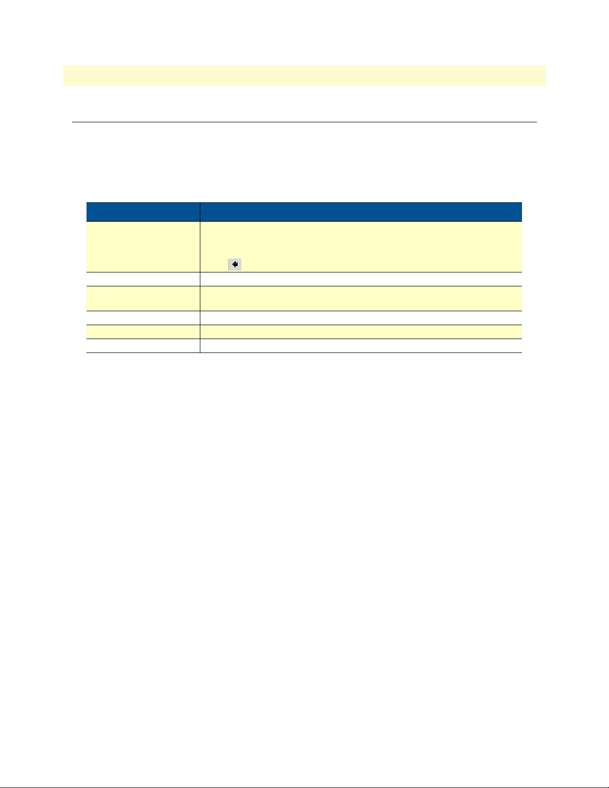
Figure 1. Model 2211 EtherBITS device server
Both devices are cost-effective single-port serial-Ethernet communication devices. The Model 2211 (see
figure 1) connects to the network via 802.11b wireless transmission. The Model 2232 (see figure 2) connects to
the network through an RJ-45 connector. Both devices support RS-232 serial communications that enable virtually any asynchronous serial device to be accessed over a network.
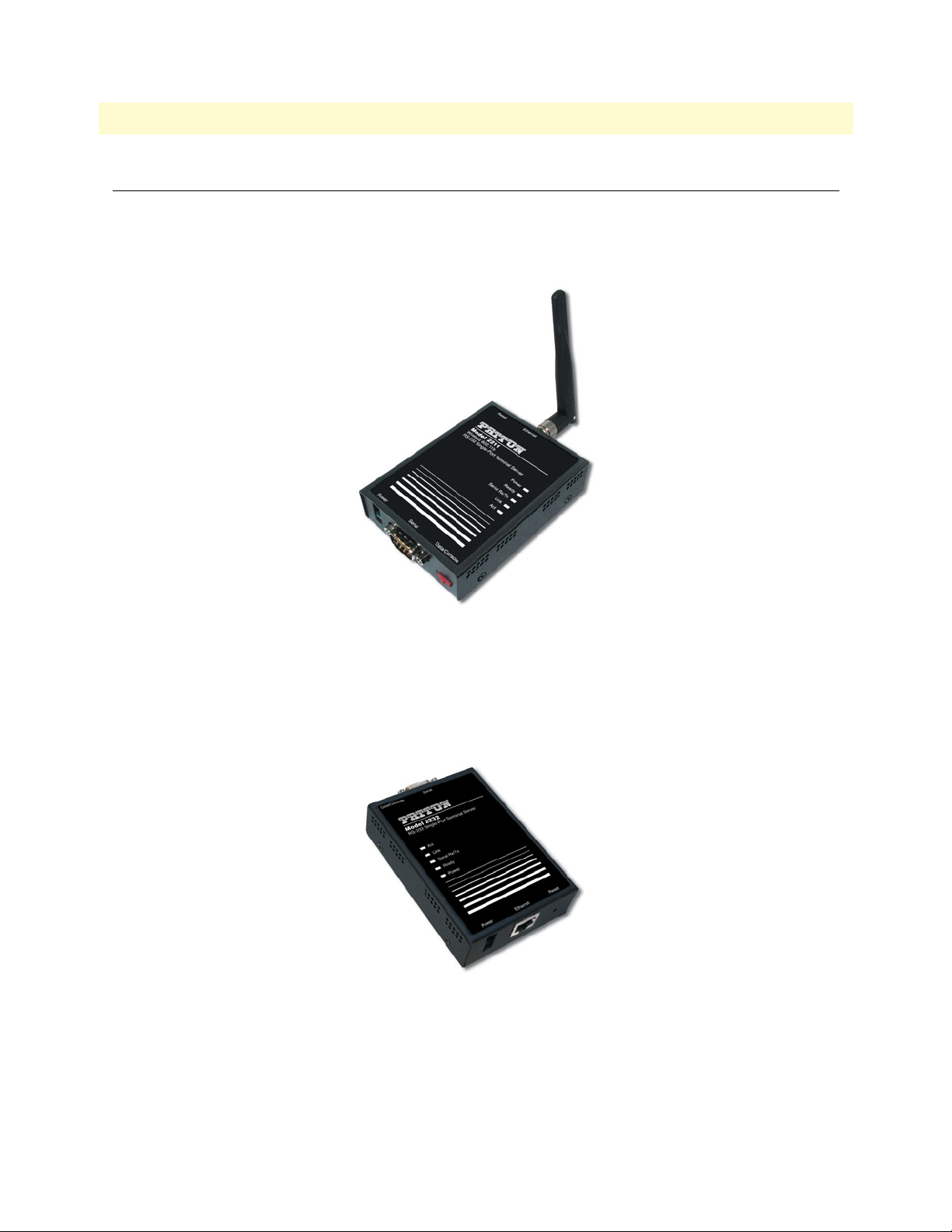
Figure 2. Model 2232 EtherBITS device server
As for the Internet connectivity, the devices open network protocols such as TCP/IP allowing serial devices to
be accessed over broadband network or conventional LAN (local area network) environment.
Introduction
Page 15

15
Models 2211 & 2232 Getting Started Guide
1 • Overview
The device servers provides a management console, by using Telnet and the serial console port, which is under
password protection. The device servers also provide a management function with the use of the EtherBITS
Manager Software Utility.
The device servers accommodate the requirements of the Retail POS, Security, Automation and
Medical marketplaces.
Note
This manual assumes user knowledge of Internetworking protocols and
serial communications
Glossary
This section defines commonly used terms in this manual. These terms are related to Internetworking, and
defined in regards to their use with device server.
MAC address
On a local area network or other network, the MAC (Media Access Control) address is the computer’s unique
hardware number. (On an Ethernet LAN, it is the same as the Ethernet address.)
It is a unique 12-digit hardware number, which is composed of 6-digit OUI (Organization Unique Identifier)
number and 6-digit hardware identifier number. The MAC address can be found on the bottom of the
original package.
Host
A user’s computer connected to the network
Internet protocol specifications define host as any computer that has full two-way access to other computers on
the Internet. A host will have a specific local or host number that, together with the network number, forms its
unique IP address.
Session
A series of interactions between two communication end points that occur during the span of a
single connection
Typically, one end point requests a connection with another specified end point. If the specified end point
replies, and agrees to the connection, the end points then take turns exchanging commands and data (talking to
each other). The session begins when the connection is established at both ends and terminates when the connection is ended.
Client/Server
Client/server describes the relationship between two computer programs in which one program, the client,
makes a service request from another program, the server, which fulfills the request.
A server is a computer program that provides services to other computer programs on one or many computers.
The client is the requesting program or user in a client/server relationship. For example, the user of a Web
browser is effectively making client requests for pages from servers all over the Web. The browser itself is a client in its relationship with the computer that is getting and returning the requested HTML file. The computer
handling the request and sending back the HTML file is a server.
Glossary
Page 16

Models 2211 & 2232 Getting Started Guide 1 • Overview
Acronyms
Acronym Definition
ISP Internet Service Provider
PC Personal Computer
NIC Network Interface Card
MAC Media Access Control
LAN Local Area Network
UTP Unshielded Twisted Pair
ADSL Asymmetric Digital Subscriber Line
ARP Address Resolution Protocol
IP Internet Protocol
ICMP Internet Control Message Protocol
UDP User Datagram Protocol
TCP Transmission Control Protocol
DHCP Dynamic Host Configuration Protocol
SMTP Simple Mail Transfer Protocol
FTP File Transfer Protocol
PPP Point-To-Point Protocol
PPPoE Point-To-Point Protocol over Ethernet
HTTP HyperText Transfer Protocol
DNS Domain Name Service
DDNS Dynamic Domain Name Service
SNMP Simple Network Management Protocol
RADIUS Remote Access for Dial-In User Service
SSH Secure Shell
NTP Network Time Protocol
UART Universal Asynchronous Receiver/Transmitter
Bps Bits per second (baud rate)
DCE Data Communications Equipment
DTE Data Terminal Equipment
CTS Clear to Send
DSR Data Set Ready
DTR Data Terminal Ready
RTS Request To Send
DCD Data Carrier Detect
Acronyms 16
Page 17

Chapter 2 Getting started
Chapter contents
Introduction..........................................................................................................................................................18
Unpacking the device server ..................................................................................................................................18
Controls, ports, and indicators...............................................................................................................................19
Connecting the hardware.......................................................................................................................................20
Connecting power ...........................................................................................................................................20
Connecting the device server to the network ...................................................................................................21
Connecting the Ethernet cable (Model 2232 only) ....................................................................................21
Connecting to the wireless LAN (Model 2211 only) .................................................................................21
Connecting to the serial device ........................................................................................................................22
Accessing the Console Port....................................................................................................................................22
Using the System console ................................................................................................................................22
Using remote console ......................................................................................................................................23
Command usage....................................................................................................................................................25
'set' Command ..........................................................................................................................................26
'get' Command .........................................................................................................................................27
'help' Command .......................................................................................................................................28
'factorydefault' Command .........................................................................................................................29
'save' Command ........................................................................................................................................29
'exit' Command ........................................................................................................................................29
'reboot' Command ....................................................................................................................................29
17
Page 18

Models 2211 & 2232 Getting Started Guide 2 • Getting started
Introduction
This chapter describes how to set up and configure the device server.
• “Unpacking the device server”—lists the contents of the device server’s shipping container
• “Controls, ports, and indicators”—Explains the layout of the device server controls and LED indicators
• “Connecting the hardware” on page 20—Describes how to connect the power, the network, and the serial
device to the EtherBITS device server.
• “Accessing the Console Port” on page 22—Describes how to access the console port by using a serial con-
sole at a local site or telnet console at a remote site.
• “Command usage” on page 25—Describes how to use command set of the device server to configure and
view parameter values and status.
The following items are required to get started:
• One DC power adapter (included in the package)
• One serial console cable for configuration (included in the package)
• One RS-232 serial cable for connecting the RS-232 serial device
• One Ethernet cable
• One PC with network interface card (hereafter, NIC) and/or one RS-232 serial port.
• Terminal emulation program running on the PC
Unpacking the device server
Inspect the shipping carton for external damage. Note any damage before removing the container contents.
Report equipment damage to the shipping carrier immediately for claim purposes. Save all packing materials in
case you need to return an item to the factory for servicing.
The device server comes with the following items:
• device server
• External 110 VAC (or 230 VAC) power supply
• Serial cable kit
• CD-ROM containing the Serial/IP, EtherBITS Device Manager, device server Quick Start Guide, and
device server Getting Started Guide
Introduction 18
Page 19
Models 2211 & 2232 Getting Started Guide 2 • Getting started
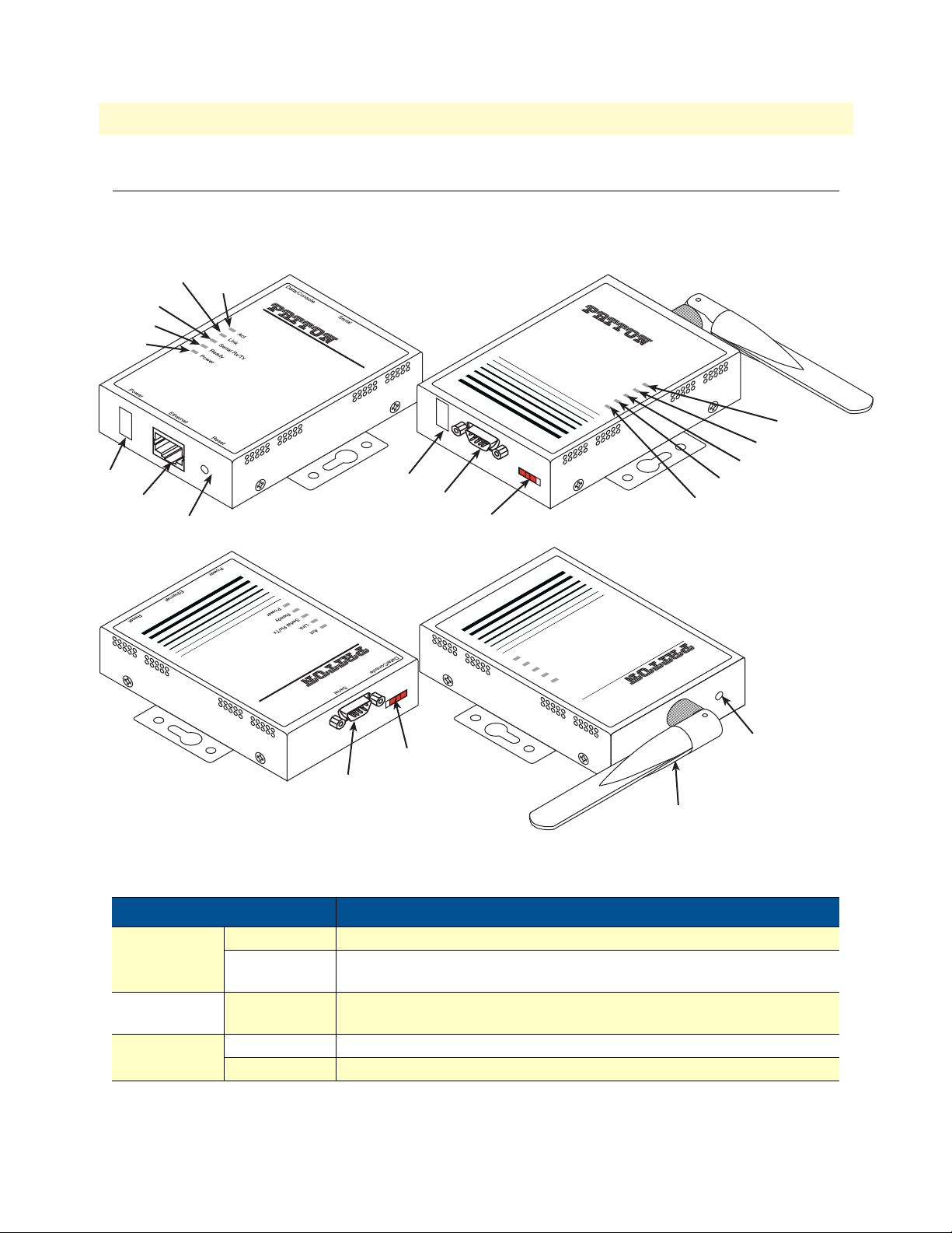
Controls, ports, and indicators
The device server has five LEDs that display the current system status (see figure 3). The serial port status LEDs
are described in table 2.
Serial Rx/Tx LED
Ready LED
Power LED
Power port
Ethernet port
Model 2232
Link LED
Reset button
Act LED
Model 2232
EtherBITS RS-232 Single-Port Device Server
Model 2232
Power port
EtherBITS RS-232 Single-Port Device Server
M
o
d
e
l 2
2
3
2
Power
Serial port
Console/Data switch
Serial
Data/Console
Serial Data/Console
Model 2211
Model 2211
EtherBITS Wireless 802.11b
RS-232 Single Port Device Server
Power
Act
Serial Rx/Tx
Link
Ready
Power
Serial Rx/Tx
Link
Act
Reset
Ready
Power
Ethernet
Act LED
Model 2211
RS-232 Single Port Device Server
EtherBITS Wireless 802.11b
Model 2211
EthernetReset
Power LED
Ready LED
Serial Rx/Tx LED
Link LED
Console/Data
Reset button
Serial port
switch
Antenna
Figure 3. Device server LEDs, switches, and ports
Table 2. Device server LEDs
Lamps Function
10 Base-T Link Green if connected to 10 Base-T Ethernet network.
Act Blinks whenever there is any activities such as incoming or outgoing pack-
ets through the device server’s Ethernet connection.
Serial port Rx/Tx Blinks whenever there is any incoming or outgoing data stream through
the serial port of the device server.
Status Ready Green if the device server is operating.
Power Red when power is supplied.
Controls, ports, and indicators 19
Page 20
Models 2211 & 2232 Getting Started Guide 2 • Getting started
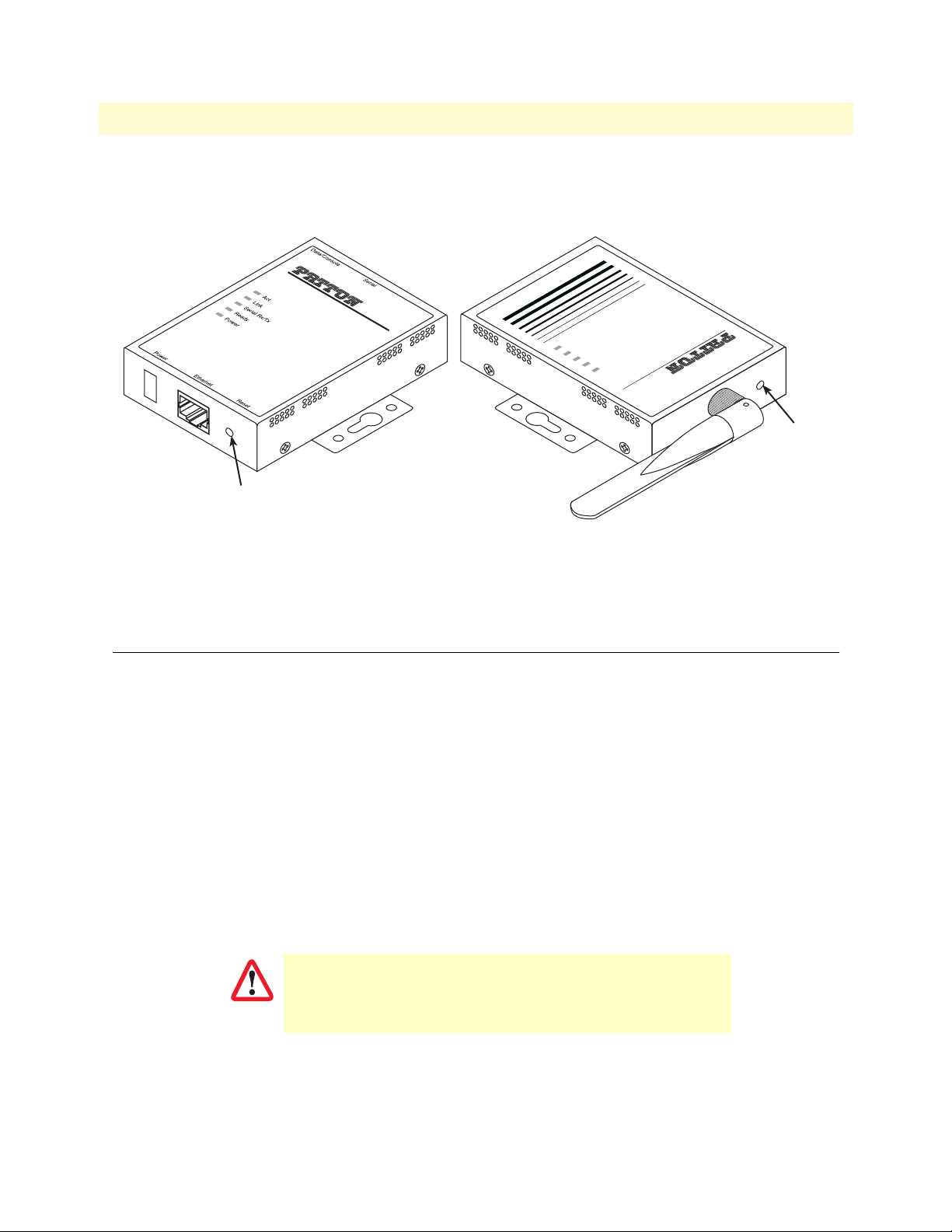
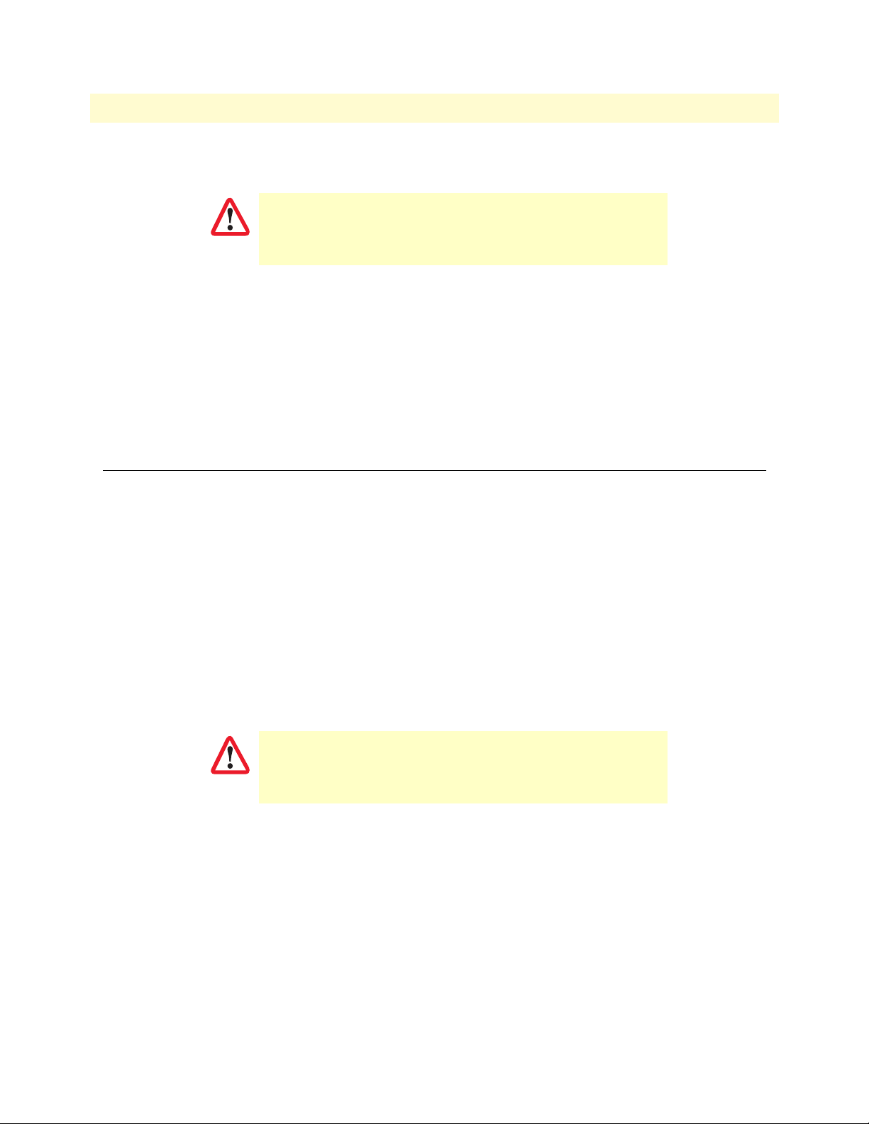
O
The Factory Reset button on the device server (see figure 4) is used to restore the device server to the factory
default configuration.
Model 2232
Model 2232
EtherBITS RS-232 Single-Port Device Server
S
e
ria
l
D
a
ta
/C
o
n
s
o
le
Act
Power
Link
Model 2211
Serial Rx/Tx
Ready
Power
RS-232 Single Port Device Server
EtherBITS Wireless 802.11b
Model 2211
EthernetReset
Reset button
Reset button
Figure 4. Factory Reset button location
The Console/Data switch (see figure 3 on page 19) enables a user to set the serial port for console or data mode.
(Refer to section “Accessing the Console Port” on page 22 for more information on serial console access)
Connecting the hardware
This section describes how to connect the device server to your equipment for initial testing.
• Connecting a power source to the device server (see section “Connecting power”).
• Connecting the device server to the network:
- Model 2232: See section “Connecting the Ethernet cable (Model 2232 only)” on page 21 to connect an
Ethernet cable between the Model 2232 and Ethernet hub or switch
- Model 2211: See section “Connecting to the wireless LAN (Model 2211 only)” on page 21 to connect
the Model device server to the wireless LAN
• Connecting the device server to a serial device through serial data cable (see “Connecting to the serial
device” on page 22).
Connecting power
The interconnecting cables shall be acceptable for external use
and shall be rated for the proper application with respect to volt-
CAUTI
age, current, anticipated temperature, flammability, and
mechanical serviceability.
1. Plug the DC power supply cable connector into the device server’s Power port (see figure 3 on page 19).
Connecting the hardware 20
Page 21

Models 2211 & 2232 Getting Started Guide 2 • Getting started
O
2. Verify that the power cord included with your device server is compatible with local standards. If it is not,
refer to chapter 5, “Contacting Patton for assistance” on page 32 to find out how to replace it with a com-
patible power cord.
3. Connect the male end of the DC power supply power cord to an appropriate AC power outlet. Verify that
the Power LED maintain a solid red.
Connecting the device server to the network
Refer to the appropriate section below to connect your device server to the network:
• Model 2232: See section “Connecting to the wireless LAN (Model 2211 only)” on page 21 to connect an
Ethernet cable between the Model 2232 and Ethernet hub or switch
• Model 2211: See section “Connecting to the wireless LAN (Model 2211 only)” on page 21 to connect the
Model device server to the wireless LAN
Connecting the Ethernet cable (Model 2232 only)
The interconnecting cables shall be acceptable for external use
and shall be rated for the proper application with respect to volt-
CAUTI
age, current, anticipated temperature, flammability, and
mechanical serviceability.
Connect the one end of the Ethernet cable to the Model 2232 10Base-T Ethernet port (see figure 3 on page 19)
and the other to the Ethernet network. If the cable is properly connected, the Model 2232 will indicate a valid
connection to the Ethernet network as follows:
• Link LED of the Model 2232 maintains solid green
• Act LED continuously blinks to indicate the incoming/outgoing Ethernet packets
If either of the above do not occur, the Model 2232 is not properly connected to the Ethernet network.
Connecting to the wireless LAN (Model 2211 only)
When power is connected correctly, the Model 2211 will automatically search for the 802.11b wireless local
area network (LAN) access point (AP) and attempt to connect to the wireless LAN AP. The Model 2211 will
indicate a valid connection to the wireless LAN AP as follows:
• The Link LED lamp on the 2211 front panel will remain solid orange.
• The Act LED lamp on the 2211 front panel will blink continuously to indicate that incoming and outgoing
wireless LAN packets are being transferred
Before connecting the Model 2211 to a wireless LAN access point, users must first set the corresponding information on the 2211, such as the SSID of the Wireless LAN access point.
Refer to chapter 3, “Wireless LAN configuration (Model 2211 only)” on page 30 to set the appropriate parameters for a wireless LAN connection.
Connecting the hardware 21
Page 22
Models 2211 & 2232 Getting Started Guide 2 • Getting started
O
O
Connecting to the serial device
The interconnecting cables shall be acceptable for external use
and shall be rated for the proper application with respect to volt-
CAUTI
age, current, anticipated temperature, flammability, and
mechanical serviceability.
Connect the serial cable to the device server Serial port (see figure 3 on page 19). To connect to the serial port
of the device, the user needs to consider the type of console port provided by the device itself. Refer to appendix C, “Cable Recommendations” on page 64 for details.
Note If the configuration of the device server through the serial console is
required, connect the serial cable to the serial port of user’s computer first.
And push the Console/Data switch (see figure 3 on page 19) to the
Console side.
Accessing the Console Port
There are two ways to access console port of the device server depending on whether the user is located at a
local site or at a remote site:
• System console: Local users can connect directly to the system console port of the device server using a
serial/data console cable (null-modem cable). To use the serial port as the console port, slide Data/Console
switch to the Console side. The serial port of the device server is used as the console port as well as the
data port.
• Remote console: Remote users can make a telnet connection to the remote console port (port 23) of the
device server via a TCP/IP network.
Both methods require the user to log into the device server in order to continue.
Using the System console
1. Connect one end of the console cable to the Serial port on the device server (see figure 3 on page 19).
The interconnecting cables shall be acceptable for external use
and shall be rated for the proper application with respect to volt-
CAUTI
age, current, anticipated temperature, flammability, and
mechanical serviceability.
2. Slide the Console/Data switch to the Console side.
3. Set the position of DIP switch for serial mode to RS-232 mode. Configuration of DIP switch is discussed
in appendix C, “Cable Recommendations” on page 64.
4. Connect the other end of the cable to the serial port of the user’s computer.
5. Run a terminal emulator program (i.e. HyperTerminal). Set the serial configuration parameters of the ter-
minal emulation program as follows:
– 9600 Baud rate
– Data bits 8
Accessing the Console Port 22
Page 23

Models 2211 & 2232 Getting Started Guide 2 • Getting started
– Parity None
– Stop bits 1
– Hardware flow control
6. Press the [ENTER] key.
7. Enter your username and password to log into the device server. The factory default user settings are
as follows.
– Login: admin
– Password: admin
8. After login, the command prompt screen will appear as follows:
login: admin
password: *****
Type 'help' to get command usages
> help
set group par1 [par2 ...] + <CR>
- group = 'ip','host','serial' or 'admin'
- par1 ... = configuration parameters. Use * to keep a parameter's value
get [group] + <CR>
- group = 'ip','host','serial','admin' or 'status'
- If group is specified, shows settings of the group.
- If group is omitted, shows settings of all groups.
factorydefault [option] + <CR>
- if option is omitted, all parameters are set with factory default values.
- if option='-ip',
all parameters except IP settings are set with factory default values.
help [group] + <CR>
- If group is omitted, shows this screen.
- If group is specified, shows 'set' command usage of the group.
save + <CR>
- Save changes
exit + <CR>
- Exit without rebooting the device
reboot + <CR>
- Exit and reboot the device
>
From the command prompt screen, users can set, get and save configuration parameter values using 'set', 'get'
and 'save' command. Users also can exit the console or reboot the device using 'exit” and 'reboot' command.
The usage of the commands can be found using 'help' command. For command usages description, please
refer to section “Command usage” on page 25.
Using remote console
The device server provides remote console feature via telnet as well as serial console so that users can access the
device server at remote site for configuration and monitoring purposes. The IP address of the device server
must be known before users can access the remote console port. The port number for the remote console is 23,
which is a TCP port number assigned for Telnet.
Accessing the Console Port 23
Page 24

Models 2211 & 2232 Getting Started Guide 2 • Getting started
Only one user can log into the remote console or serial console at a time. If the serial console is established
while a remote console is established, current remote console will be halted and no more remote console will be
established until serial console is finished.
To access the remote console of the device server, do the following:
1. Run a telnet program or a program that supports telnet functions such as TeraTerm-Pro or HyperTermi-
nal. The target IP address and the port number should be those of the device server. If required, specify the
port number as 23. Type the following command in the command line interface of your computer.
telnet 192.168.1.254
Or run a Telnet program with the parameters shown in figure 5:
Figure 5. Telnet program set up example (TeraTerm Pro)
2. The user has to log into the device server. Type the user name and password. A factory default setting of
the user name and password are both admin.
3. If the user logged into the device server successfully, the same command prompt screen as the one of serial
console will be displayed. The user can set, get, save configuration parameters and exit console, reboot the
device as like the serial console.
Accessing the Console Port 24
Page 25

Models 2211 & 2232 Getting Started Guide 2 • Getting started
Command usage
The device server provides several simple commands for configuration and control of the device server. Table 3
summarizes command set which the device server supports.
Table 3. Device server command set summary
Command Description Result
set group par1 [par2 ...] + <CR> Set configuration parameters:
• group = 'ip', 'host', 'serial' or
'admin'
• par1 ... = configuration parameters. Use * to keep a parameter's value
get [group] + <CR> Get configuration parameter values
• group = 'ip', 'host', 'serial',
'admin' or 'status'
• If group is specified, shows settings of the group.
• If group is omitted, shows settings of all groups.
help [group] + <CR> Shows command usage screen.
• If group is omitted, shows
help screen.
• If group is specified, shows 'set'
command usage of the group.
factorydefault [option] + <CR> Restore factory default values
• If option is omitted, all parameters are set with factory default
values.
• If option='-ip', all parameters
except IP settings are set with
factory default values.
save + <CR> Save changes If success,
exit + <CR> Exit without rebooting the device
(changes are not applied)
reboot + <CR> Exit and reboot the device None
If success,
“OK” + <CR> + <LF>
If error
“ERROR” + <CR> + <LF>
Parameter value display
Help message display
If success,
“OK” + <CR> + <LF>
If error
“ERROR” + <CR> + <LF>
“OK” + <CR> + <LF>
If error
“ERROR” + <CR> + <LF>
If success,
“OK” + <CR> + <LF>
If error
“ERROR” + <CR> + <LF>
Command usage 25
Page 26

Models 2211 & 2232 Getting Started Guide 2 • Getting started
'set' Command
With set command, users can configure parameter values of the device server for each environment. Basic set
command usage is as follows:
set group par1 [par2 ...] + <CR>
where,
group = 'ip','host','serial' or 'admin'
par1 par2 ... = configuration parameters. Use * to keep a parameter's value
The 'group' is the category where the parameters should be entered. For example, if users want to set parameters related to the IP configuration, use set command as shown in the following example.
> set ip static 192.168.1.100 255.255.255.0 192.168.1.1
OK
>
In the above example, the first parameter 'ip' indicates that the following parameters are IP configuration
parameters. The second parameter 'static' indicates that the device server will use static IP address of the third
parameter '192.168.1.100'. The fifth parameter indicates the subnet mask and the next indicates the default
gateway IP address.
If users want to change only one of the parameters of the group, users can omit trailing parameters and/or can
use '*' to keep a parameter value. The example below shows how to change subnet mask only without changing
IP address and gateway IP address.
> set ip static * 255.255.0.0
OK
>
Command usage of set will differ depending on the groups. Each set command usage of the group can be
found using help group command. For example, if users want to know how to use set command to configure
IP configuration, typing 'help ip' + <CR> will show 'set' command usage for the IP configuration as
shown below.
> help ip
set ip ipmode par1 par2 ...
- ipmode: static=Static IP / dhcp=DHCP / pppoe=PPPoE
- parameters:
if ipmode = static,
par1 = IP address,
par2 = subnet mask,
par3 = gateway
if ipmode = dhcp,
no parameters required
if ipmode = pppoe,
par1 = PPPoE username,
par2 = PPPoE password
>
Note The changed values will not take effect until save and reboot commands are
invoked. For more details, refer to section “'save' Command” on page 29
and section “'reboot' Command” on page 29.
Command usage 26
Page 27

Models 2211 & 2232 Getting Started Guide 2 • Getting started
'get' Command
With get command, users can view the current parameter values and status of the device server. Basic get command usage is as follows:
get [group] + <CR>
where,
group = 'ip','host','serial' , 'admin' or 'status'
- If group is specified, shows settings of the group.
- If group is omitted, shows settings of all groups.
The group means the category where parameters belong to as like set command. For example, if users want to
view parameter values related to IP configuration, use the get command as shown below.
> get ip
IP_mode: static
IP_address: 192.168.1.100
Subnet_mask: 255.255.255.0
Gateway: 192.168.1.1
>
'status' group is a special group where set command does not apply. get status will display current system status
as shown below (example shows Model 2232 information):
> get status
Serial_no.: 2232-0207_test
MAC_address: 00-01-95-77-88-99
F/W_REV.: V1.2.0
Current_IP: 192.168.0.125
>
If group is omitted, get command will show all of the parameter values as shown below (example shows Model
2232 information).
> get
--- Status --Serial_no.: 2232-0207_test
MAC_address: 00-01-95-77-88-99
F/W_REV.: V1.2.0
Current_IP: 192.168.0.125
--- Admin --Username: admin
Password: admin
Devicename: 2232 Device
--- IP --IP_mode: dhcp
--- Host --Host_mode: tcps
Local_port: 6001
Inactivity_timeout(sec): 300
--- Serial --Baudrate: 9600
Data_bits: 8_bits
Parity: None
Command usage 27
Page 28

Models 2211 & 2232 Getting Started Guide 2 • Getting started
Stop_bits: 1_bit
Flow_control: None
DTR_option: Always_high
DSR_option: None
Interchar_timeout(ms): 50
>
'help' Command
With help command, users can find command usage help in the console screen. Basic command usage is
as follows:
help [group] + <CR>
where,
if group is omitted, overall help screen will be displayed
if group is specified, 'set' command usage of specified group will be displayed.
The following shows the help screen when no group is specified
> help
set group par1 [par2 ...] + <CR>
- group = 'ip','host','serial' or 'admin'
- par1 ... = configuration parameters. Use * to keep a parameter's value
get [group] + <CR>
- group = 'ip','host','serial','admin' or 'status'
- If group is specified, shows settings of the group.
- If group is omitted, shows settings of all groups.
help [group] + <CR>
- If group is omitted, shows this screen.
- If group is specified, shows 'set' command usage of the group.
factorydefault [option] + <CR>
- if option is omitted, all parameters are set with factory default values.
- if option='-ip',
all parameters except IP settings are set with factory default values.
save + <CR>
- Save changes
exit + <CR>
- Exit without rebooting the device
reboot + <CR>
- Exit and reboot the device
The following shows the help screen with 'ip' group specified.
> help ip
set ip ipmode par1 par2 ...
- ipmode: static=Static IP / dhcp=DHCP / pppoe=PPPoE
- parameters:
if ipmode = static,
par1 = IP address,
par2 = subnet mask,
par3 = gateway
if ipmode = dhcp,
no parameters required
if ipmode = pppoe,
par1 = PPPoE username,
par2 = PPPoE password
Command usage 28
Page 29

Models 2211 & 2232 Getting Started Guide 2 • Getting started
'factorydefault' Command
With factorydefault command, users can load factory default parameter values in console. Command usage of
factorydefault is as follows:
factorydefault [option] + <CR>
where:
• If option is omitted, all parameters are set with factory default values.
• If option = -ip, all parameters except IP settings are set with factory default values.
Loaded values are not saved until the save command is invoked. After the factorydefault command has been
used, the save and reboot commands are required as follows for changes to take effect.
> factorydefault (or factorydefault -ip)
OK
> save
OK
> reboot
'save' Command
With save command, current parameter changes are saved to non-volatile memory. Command usage of save
command is as follows:
save + <CR>
Saved changes will be applied if the device server is rebooted by reboot command or manual rebooting.
'exit' Command
With exit command, current serial or remote console session will be closed. However, changed parameters are
not applied until the device server is manually rebooted. Command usage of exit command is as follows:
exit + <CR>
'reboot' Command
With reboot command, the device sesrver will be rebooted immediately. Changed parameter values will be
applied when the device server is up again. Command usage of reboot is as follows:
reboot + <CR>
Command usage 29
Page 30

Chapter 3 Wireless LAN configuration
(Model 2211 only)
Chapter contents
Introduction..........................................................................................................................................................31
Infrastructure Mode and Ad-hoc Mode ..........................................................................................................31
Network Name: SSID (Service Set Identifier) .................................................................................................31
Channel ..........................................................................................................................................................31
Security ...........................................................................................................................................................31
Settings..................................................................................................................................................................32
SSID ...............................................................................................................................................................32
WEP1 .............................................................................................................................................................32
WEP2 .............................................................................................................................................................33
WEP Key ........................................................................................................................................................33
30
Page 31

Models 2211 & 2232 Getting Started Guide 3 • Wireless LAN configuration (Model 2211 only)
Introduction
IEEE 802.11, a wireless LAN standard, is the basic network element used by this device. It requires one or
more nodes and a wireless LAN access point (AP). Often, the word node refers to the notebook computers, personal computers, and PDAs that use wireless LAN cards. In this guide, node will refer to the Model device
server device server.
Infrastructure Mode and Ad-hoc Mode
An AP is most often used to connect the Model device server to the Ethernet LAN. However, it can also be
used to connect to the Internet. This type of connection is referred as an infrastructure mode. On wireless computer networks, ad-hoc mode, also called peer-to-peer mode, is a method for device server devices to directly
communicate with each other without an AP. Ad-hoc mode can be very useful in replacing cables between
existing devices with a wireless connection.
Network Name: SSID (Service Set Identifier)
A wireless LAN network can be configured under different names at depending on the AP’s configuration.
SSID is an ID value that distinguishes one wireless network from another. If a network is configured in the
infrastructure mode, users need to input and set the target AP's SSID into device server so that the device
server can communicate with the target AP. Therefore, users need first to check the target AP’s SSID. On the
other hand, when using the ad-hoc mode, inter-communicating device servers should have the same SSID.
The SSID can be set to a maximum length of 32 bytes, and it can be set using ASCII characters or hexadecimal
(hex) numbers.
Channel
The device server searches for all accessible 802.11b Wireless LAN channels periodically to find other APs.
When the device server is first booted up, it searches for a preset AP (default value is Default). When the AP is
found, it accesses the AP automatically. The device server will use the channel belonging to the network group
in which it belongs. When using the infrastructure mode, the device server checks the channel values being
used in AP, and automatically sets the channel values to be identical to the AP channels values. In ad-hoc
mode, the two channels in device server should be given identical values.
Even when a certain value or an asterisk ('*') symbol is entered in a channel value entry using the set command, the device server will ignore those values and automatically set the values as the AP channel values of the
group in which it belongs.
Security
802.11b based applications are different from wired Ethernet applications in the way they support security
functions. The 802.11 Committee recognizes that the wired Ethernet supports a very high level of internal
security. Therefore, when creating policies for wireless LAN standards, the Committee has aimed to ensure that
Wireless has the same high level of security as that of the Ethernet.. WEP (wired equivalent privacy) uses RSA
Security’s RC4 PRNG encryption algorithm and 40-bit shared key to encrypt data. Thus, in the device server,
5 bytes of ASCII characters or 10-digit hex numbers are used to represent 64 bits of WEP1, and 13 bytes of
ASCII characters or 26-digit hex numbers are used to represent 128 bits of WEP1. The shortcoming of WEP is
that it can encrypt only the body of the data frame. Frame headers and other types of frames are not encrypted.
Introduction 31
Page 32

Models 2211 & 2232 Getting Started Guide 3 • Wireless LAN configuration (Model 2211 only)
Settings
For proper operation of the device server in a wireless environment, users must set the wireless parameters in
the device server’s
ment. To do this, users must check the following:
• Type of Wireless LAN network (infrastructure/ad-hoc)
• Wireless LAN SSID and channel
• Whether a Wireless LAN WEP is used, and the WEP setting status (number of bits, key values, and
coding methods)
• Whether Wireless LAN authentication protocols are used for the Wireless LAN connection
Some Wireless LAN networks require authentication protocols (like MD5).
Users can check the current Wireless LAN settings by using console commands:
> get wlan
SSID: Default
Type: Infrastructure
National Code: Korea
Encryption Type: 64bit
Key Input Method: Hexadecimal
WEP Key: 1234567890
>
wireless LAN according to the requirements of the designated wireless LAN network environ-
Table 4. Wireless LAN setting parameters
Parameter Values
SSID Default / (Max 16 32 characters)
Type Infrastructure mode or Ad-hoc mode
Channel CH .1-CH.13 (can be checked during booting sequence)
Encryption Type None(0), 64 or 128 bits
Key Input Method ASCII or Hexadecimal
Table 4 parameters are described in the following sections.
SSID
Factory default value of SSID is Default. User can change this value according to the SSID of his AP to be
used. If the value of SSID in device server is not changed from factory default value, Default, device server
scans APs in the neighborhood and selects the AP that has the strongest signal level automatically. This auto
scan and selection is continued until the valued of SSID is changed from Default at every reboot. But if there is
an AP with Default SSID, device server will connect to this AP first.
WEP1
If the WEP function is to be used, a WEP key value must be set. The WEP1 key field is used to select between
a 64-bit key or a 128-bit key. If WEP1 is set to 0, the WEP function will be disabled.
Settings 32
Page 33

Models 2211 & 2232 Getting Started Guide 3 • Wireless LAN configuration (Model 2211 only)
WEP2
The WEP2 field selects whether ASCII code or hexadecimal code will be used to represent the data values
in WEP1.
WEP Key
The WEP Key field is for user authentication. If the WEP1 value is 64 bits, the user must enter a 5-characters
ACSII password in ASCII mode or 10-digit hexadecimal password in hexadecimal mode. If the WEP1 value is
128 bits, the user must enter a 13-characters ASCII password in ASCII mode or 26-digit hexadecimal password in hexadecimal mode. For example, if WEP2 is set as a hex code type, the user could enter 0123456789
(when WEP1 is set to 64 bits), or 0123456789ABCDEF0123456789 (when WEP2 is set to 128 bits).
The basic set commands for wireless LAN (wlan) settings are as follows:
set wlan SSID type National_code ch WEP1 WEP2 WEP_Key
- SSID: Max 32 character(Use double quotation mark to include space character)
- type: i=infrastructure / a=AdHoc
- National_Code:
1.USA/2.Canada/3.EU,Australia/4.Spain/5.France/6.Korea/7.Japan/8.Others
- ch: set channel number when adhoc mode
- WEP1: 0=none / 1=64bit / 2=128bit
- WEP2: a=ASCII type pass,h=Hexdecimal type pass
- WEP_Key: ASCII type = 5(64bit) or 13(128bit) character input,
- Hexdecimal type = 10(64bit) or 26(128bit) number input
Note If the type is set as infrastructure, channel will be set to the same value of the
connected AP internally regardless of the value set by the user.
The following examples show the commands needed to configure the device server’s wireless LAN settings:
• SSID=Default, National Code=Korea, infrastructure , arbitrary channel number, WEP Key disabled
> set wlan Defalut i 6 * 0(National Code: Korea, WEP Key disabled)
• SSID=Default, National Code=Korea, Adhoc , channel number=4, WEP Key disabled
> set wlan Default a 6 4 0
• SSID=Default 1, National Code=Korea, Adhoc , channel number=4, WEP Key disabled (If there are space
characters in SSID, you should use a double quotation mark to set SSID.)
> set wlan “Default 1” a 6 4 0
Settings 33
Page 34

Chapter 4 IP address configuration
Chapter contents
Introduction..........................................................................................................................................................35
Static IP.................................................................................................................................................................35
Static IP configuration ....................................................................................................................................36
DHCP...................................................................................................................................................................36
DHCP Configuration .....................................................................................................................................37
IP Filtering ............................................................................................................................................................37
34
Page 35

Models 2211 & 2232 Getting Started Guide 4 • IP address configuration
Introduction
A valid IP address of the device server needs to be assigned before it starts to work in the user's network environment. A network system administrator may provide the user with this IP address setting information for
the network. The IP address must be unique within the network. Otherwise, the device server will not have a
valid connection to the network.
Users can choose the desired IP mode out of the two IP operating modes, i.e., Static IP and DHCP. The factory default IP mode is DHCP mode. Table 5 shows the parameter items for IP configuration.
Table 5. IP configuration parameters
Static IP IP address
Subnet mask
Default gateway
DHCP No parameters required
Basic set command usage for IP configuration is as follows:
set ip ipmode par1 par2 ...
where,
ipmode: 'static' for Static IP / 'dhcp' for DHCP
parameters:
if ipmode = static,
par1 = IP address, par2 = subnet mask, par3 = gateway
if ipmode = dhcp,
no parameters required
Static IP
In the Static IP mode, users have to manually specify all the parameters such as IP addresses of the device server,
valid subnet mask and the default gateway IP address.
IP address is an identification number assigned to a computer as a permanent address on the network. Computers use IP addresses to identify and talk to each other on the network. Choose a proper IP address which is
unique and valid for your network environment.
A subnet represents all the network hosts at one geographic location, in one building, or on the same local area
network. When there is any outgoing packet over the network, the device server will check whether the desired
TCP/IP host, specified in the packet, is on the local network segment with the help of the subnet mask. If the
address is proven to be on the same network segment as the device server, the connection is established directly
from the device server. Otherwise, the connection is established through the given default gateway.
A gateway is a network point that acts as an entrance to another network. Usually, the computers that control
traffic within the network or at the local Internet service provider are gateway nodes. The device server needs to
know the IP address of the default gateway computer in order to communicate with the hosts outside the local
network environment. For correct information on the gateway IP address, refer to the network administrator.
Introduction 35
Page 36

Models 2211 & 2232 Getting Started Guide 4 • IP address configuration
Static IP configuration
To configure IP configuration parameters of the device server, use set command as follows:
set ip static ip_address subnet_mask default_gateway + <CR>
where,
ip_address = IP address of the device server
subnet_mask = Subnet mask
default_gateway = Default gateway IP address
To apply changes, users have to invoke save and reboot commands after changing configuration.
> set ip static 192.168.1.10 255.255.255.0 192.168.1.1
OK
DHCP
Dynamic Host Configuration Protocol (DHCP) is a communications protocol that allows network administrators to manage and automate the assignment of IP addresses centrally in an organization's network. DHCP
allows a network administrator to supervise and distribute IP addresses from a central point and automatically
send a new IP address when a computer is plugged into a different place in the network.
As described in the section 4.1, the IP address must be entered manually at each computer in Static IP mode
and, if computers move to another location in another part of the network, a new IP address must be entered.
Meanwhile, all the parameters including the IP address, subnet mask, gateway, DNS servers will be automatically configured when the IP address is assigned in DHCP mode. DHCP uses the concept of a "lease" or
amount of time for which a given IP address will be valid for a computer. All the parameters required are
assigned by the DHCP server, and each DHCP client computer receives the proper network information
at boot-up.
To obtain an IP address, the device server sends a corresponding DHCP request as a broadcast over the network after each reset. The reply generated by the DHCP server contains the IP address as well as the subnet
mask, gateway address, DNS servers and the lease time. The device server immediately places this information
in its non-volatile memory. If the operating time reaches the lease time, the device server will request the
DHCP server for renewal of its lease time. If the DHCP server approves extending the lease, the device server
can continue to work with the current IP address. Otherwise, the device server will start the procedure to
request a new IP address to the DHCP server.
A DHCP sever assigns IP addresses dynamically from an IP address pool, which is managed by the network
administrator. This means DHCP client, i.e. the device server, receives a different IP address each time it boots
up. To prevent the case that users do not know the IP address of the device server in such environments, its IP
address should be reserved on the DHCP server side. In order to reserve the IP address in the DHCP network,
the administrator needs the MAC address of the device server found on the label sticker at the bottom of the
device server:
MAC=00:0B:6B:19:16:9E
DHCP 36
Page 37

Models 2211 & 2232 Getting Started Guide 4 • IP address configuration
DHCP Configuration
To set the device server to work in DHCP mode, just set IP mode to DHCP as follows:
> set ip dhcp
OK
>
IP Filtering
The device server has an IP address based filtering feature to prevent unauthorized remote hosts from accessing
device server. The user can allow one of the following scenarios by changing the parameter settings:
• Only one host of a specific IP address can access the device server
• Hosts on the a specific subnet can access the device server
• Any host can access the device server
The user may allow a host or a group of hosts to access the device server. Then the user must enter the IP
address and subnet to be allowed for accessing.
To allow only a specific host to the device server, enter the IP address of the specific host and just give
255.255.255.255 for the subnet. To allow any hosts to the device server, give 0.0.0.0 for both of the IP address
and subnet. Refer to table 6 for more details.
Table 6. Input examples of allowed remote hosts
Allowable Hosts
Any host 0.0.0.0 0.0.0.0
192.168.1.120 192.168.1.120 255.255.255.255
192.168.1.1-192.168.1.254 192.168.1.0 255.255.255.0
192.168.0.1-192.168.255.254 192.168.0.0 255.255.0.0
192.168.1.1-192.168.1.126 192.168.1.0 255.255.255.128
192.168.1.129-192.168.1.254 192.168.1.128 255.255.255.128
Input format
Base Host IP address Subnet mask
For example, to allow only a 192.168.1.120 host for accessing, enter the following commands,
1. DHCP mode
IP Filtering 37
Page 38

Models 2211 & 2232 Getting Started Guide 4 • IP address configuration
> set ip dhcp 192.168.1.120 255.255.255.255
OK
> save
OK
> reboot
2. Static IP mode (ip: 192.168.161.5 , subnet: 255.255.0.0 , gateway:192.168.1.1)
> set ip static 192.168.161.5 255.255.0.0 192.168.1.1 192.168.1.120 255.255.255.255
OK
> save
OK
> reboot
IP Filtering 38
Page 39

Chapter 5 Host Mode configuration
Chapter contents
Introduction..........................................................................................................................................................40
TCP Server Mode Operations ...............................................................................................................................42
TCP Server Mode Configuration ....................................................................................................................43
TCP Client Mode Operations...............................................................................................................................44
TCP Client Mode Configuration ....................................................................................................................46
TCP Server/Client Mode Operations ....................................................................................................................47
TCP Server/Client Mode Configuration .........................................................................................................49
39
Page 40

Models 2211 & 2232 Getting Started Guide 5 • Host Mode configuration
Introduction
Host mode represents the operating session mode of the device server. Several host modes are available for the
data communication between the serial device and remote hosts. Since TCP is connection-oriented protocol,
server, client, server/client modes are provided. Table 7 shows the brief description of the host modes. A factory
default host mode is TCP Server.
Table 7. Device server TCP/IP session modes
Mode Description
TCP server Select this mode, when users want the device server to operate as a TCP server.
The device server stands by until there is any TCP connection request. If TCP connection is not already established at that time, the device server accepts the
request and the session is established. In the established state, it transmits the data
through the serial port if there is any data from the remote host. Since the device
server supports only one TCP session for the serial port, the additional TCP connection request will be rejected if already established. This mode is useful when users
want to send data to the serial device at any time they want.
TCP client Select this mode, when users want the device server to operate as a TCP client.
When the serial device sends data or pre-defined timer is expired, the device
server tries to establish a TCP connection to a remote server through its TCP port. If
a TCP session is established between them, the device server will send data to the
server. If there’s any data from the server during the session, it will also send the
data through the serial port. However, if the device server failed to connect to the
remote server, the data from the serial port will be discarded. This is useful when
the serial device initiates sending data such as data gathering application.
TCP server/client If you are not sure which mode to choose, select this mode since it will be applied
in most applications. In this mode, the device server operates as TCP server AND
client. If the connection is not established, it will accept all incoming connection
and connect to the remote host if there are any data from the serial device. Otherwise, it will send data back and forth. In summary, the device server will work as if
it is virtually connected to the remote host.
For each host mode, required parameters for configuration is summarized in table 8.
Table 8. Host mode configuration parameters
TCP Server Listening TCP port
Inactivity timeout (sec)
TCP Client Destination IP
Destination TCP Port
Cyclic connection Interval
Inactivity timeout (sec)
TCP Server/Client Listening TCP port
Destination IP
Destination TCP Port
Cyclic connection Interval
Inactivity timeout (sec)
Introduction 40
Page 41

Models 2211 & 2232 Getting Started Guide 5 • Host Mode configuration
Basic set command usage for host mode configuration is as follows:
set host hostmode par1 par2 ...
where,
hostmode: tcps=TCP server / tcpc=TCP client / tcpsc=TCP server & client
parameters:
if hostmode = TCP server (tcps),
par1 = listening TCP port,
par2 = inactivity timeout (sec)
if hostmode = TCP client (tcpc),
par1 = destination IP address,
par2 = destination TCP port,
par3 = cyclic connection interval (min),
par4 = inactivity timeout (sec)
if hostmode = TCP server & client (tcpsc),
par1 = listening TCP_port,
par2 = destination IP address,
par3 = destination TCP port,
par4 = cyclic connection interval (min),
par5 = inactivity timeout (sec)
* set cyclic connection interval to 0 not to use cyclic connection
* set inactivity timeout to 0 for unlimited timeout
For easier understanding of TCP modes, a simplified State Transition Diagram is often used. And too help
users understand the diagram, the TCP state of the device server is briefly described as follow:
• Listen: It represents “a waiting for a connection request from any remote host”. It is a default start-up mode
when it is set as TCP server mode. This state is valid only in TCP server mode operation.
• Closed: It means “No connection state at all”. If the data transfer is completed, the state is changed to this
state if one of the host requests disconnection request. If it is in TCP server mode, the state is automatically
changed to [Listen] mode. It is a default start-up mode when it is set as TCP client mode or TCP server/client
mode.
• Sync-Received: In TCP server mode, the state will be changed from [Listen] to [Sync-Received], if any
remote host sends connection request. If the device server accepts the request, the state will be changed into
[Established]. This state is not valid in TCP client mode.
• Sync-Sent: If the device server sends a connection request to a remote host, the state is changed from
[Closed] to [Sync-Sent]. This state is maintained until the remote host accepts the connection request. This
state is valid only in TCP client mode.
• Established: It represents “an open connection”. If one of the hosts accepts a connection request from the
other host, the connection is opened and state is changed into [Established].
• Data: When it is in [Established] state, data from a host will be transferred to the other one. For easier
understanding of the TCP session operation, we called the state as [Data] state when actual data transfer is
performed. Actually, the [Data] mode is a part of [Established] state as is described in the RFC 793 [Transmission Control Protocol]. This is a normal state for the data transfer phase of the connection.
Introduction 41
Page 42

Models 2211 & 2232 Getting Started Guide 5 • Host Mode configuration
TCP Server Mode Operations
The device server works as a TCP server, and the default TCP state is [Listen] in this mode. The device server
supports only one TCP socket connection per one serial port. If a connection is currently established, the additional connection requests will be rejected. The remote host will be either Ethernet-Serial communication
devices acting as a TCP client or a socket program acting as a TCP client running on users' PC.
1) Typical State Transition
[Listen] --> [Sync-Received] --> [Established] --> [Data] --> [Closed] --> [Listen]
At start-up, an initial TCP state is [Listen]. If there is any incoming TCP connection request, the state will be
changed into [Sync-Received], then [Established], which means a session is opened. For a while, data will be
transferred between the hosts. This is the [Data] state. The session will be disconnected due to the request of
one of them, which is [Closed] state. And then, the state is automatically changed to its original state, [Listen].
2) Operations
Serial data transfer
When a session has been established, the device server reads the data from the serial port buffer till internal
serial buffer is full or inter-character time interval reaches the time specified as inter-character timeout value.
Then, it transfers the data to the IP address of the remote host. If there's no remote host connected to the
device server, all the incoming data from the serial port are discarded.
Session disconnection
The connected session will be disconnected when the remote host sends disconnection request or when no
data transfer activity is found through the serial port for a certain amount of time, which is
“Inactivity timeout”.
TCP Server Mode Operations 42
Page 43

Models 2211 & 2232 Getting Started Guide 5 • Host Mode configuration
Figure 6 shows the State Transition Diagram of the session operations in TCP server mode.
Figure 6. State Transition Diagram of TCP server mode
TCP Server Mode Configuration
To configure the device server to work as a TCP server, use set command as follows:
set host tcps listening_TCP_port inactivity_timeout + <CR>
where,
listening_TCP_port: Listening TCP port
Inactivity_timeout: Inactivity timeout in seconds.
Listening TCP port is the TCP port number through which remote host can connect a TCP session, and, send
and receive data. Incoming connection request to the ports other than Listening TCP Port will be rejected. The
device server does not restrict the number to a specific range, but it is strongly recommended not to use the
well-known ports for certain application (See Appendix D. Well-known Port Numbers). To change the port
number, select menu 2 on the TCP Server mode configuration screen.
Inactivity timeout is set to maintain the TCP connection state as Closed or Listen in TCP host mode unless
there is any data transfer between the serial device and the device server. If there is no incoming or outgoing
TCP Server Mode Operations 43
Page 44

Models 2211 & 2232 Getting Started Guide 5 • Host Mode configuration
data through the serial port during the specified inactivity timeout interval, the existing TCP connection will be
closed automatically.
If the value of inactivity timeout is set to 0, the current TCP connection is maintained unless there's no connection close request. Although inactivity timeout is disabled, the device server will check the connection status
between the device server and the remote host by sending “keep alive” packets periodically. If the remote host
does not answer the packets, it is regarded that the connection is down unintentionally. Then, the device server
will force to close the existing TCP connection.
Note At least, this value should be set larger than that of inter-character timeout. To
prevent the unintended loss of data due to the session disconnection, it is
highly recommended that this value is set large enough so that the intended
data transfer is completed.
The following example shows how to set TCP server mode:
> set host tcps 6001 300
OK
>
TCP Client Mode Operations
The device server works as a TCP client, and the default TCP state is [Closed] in this mode. The remote host
will be either Ethernet-Serial communication devices acting as a TCP server or a socket program acting as a
TCP server running on users' PC.
1) Typical State Transition
[Closed] --> [Sync-Sent] --> [Established] --> [Data] --> [Closed]
At start-up, an initial TCP state is [Closed]. If there is any incoming data through the serial port, the device
server will try to connect to a user-defined remote host. Then, the state will be changed to [Sync-Sent], which
means the connection request is being sent. If the remote host accepts the request, the state will be changed
into [Established], which means a session has been opened. For a while, data will be transferred between the
hosts. This is [Data] state. The session will be disconnected due to the request of one of them, which is its original state, [Closed].
2) Operations
Serial data transfer
Whenever the serial device sends data through the serial port of the device server, data will be accumulated
to the serial port buffer of the device server. If the internal serial port buffer is full or inter-character time
interval reaches to the time specified as inter-character timeout value, it tries to connect to the user-defined
IP address of the remote host, if TCP session is not established yet. If the device server successfully connects to the remote host, the data in the serial port buffer will be transferred to the host. Otherwise, all the
data stored in the buffer will be cleared.
TCP Client Mode Operations 44
Page 45

Models 2211 & 2232 Getting Started Guide 5 • Host Mode configuration
Session disconnection
The connected session will be disconnected when the remote host sends disconnection request or when no
data transfer activity is found through the serial port for certain amount of time, which is “Inactivity time-
out”. All the data remained in the serial port buffer will be cleared when it is disconnected.
Connection request from remote host
All the incoming TCP connection requests will be rejected in TCP client mode.
Cyclic Connection
If Cyclic Connection function is enabled, the device server will make an attempt to connect to the user-
defined remote host at certain interval even if there is no incoming serial data from the device. If the
remote host prepares certain data, it will be transferred to the serial device via its serial port after the connection is established. Eventually, users can monitor the serial device periodically by making the remote
host send the serial command to the device server whenever it is connected to the remote host. This option
is useful when users need to gather the device information periodically even if the serial device does not
TCP Client Mode Operations 45
Page 46

Models 2211 & 2232 Getting Started Guide 5 • Host Mode configuration
send its data periodically. Figure 7 shows the State Transition Diagram of the session operations in TCP
client mode.
Figure 7. State Transition Diagram of TCP client mode
TCP Client Mode Configuration
To configure the device server to work as a TCP client, use set command as follows:
set host tcpc dest_ip dest_port cyclic_connection_interval inactivity_timeout + <CR>
where,
dest_ip = destination IP address
dest_port = destination TCP port
cyclic_connection_interval = cyclic connection interval in minutes
inactivity_timeout = inactivity timeout in seconds.
TCP Client Mode Operations 46
Page 47

Models 2211 & 2232 Getting Started Guide 5 • Host Mode configuration
Destination IP address and destination TCP Port are the information on the remote host to which the device
server will try to connect in TCP client mode. The IP address (or domain name) should be specified together
with the TCP port number.
Cyclic connection interval is the time interval at which the device server will try to connect to the remote host
regardless of the existence of incoming data from the serial port. If the interval is specified with a valid value
other than 0, the function is enabled. The time interval will be the specified value by the unit of minute. If the
interval is entered as 0, cyclic connection feature will be disabled.
Inactivity timeout is the same as described in TCP server mode setting section.
The following example shows how to set TCP client mode:
> set host tcpc 192.168.1.1 6001 10 300
OK
>
TCP Server/Client Mode Operations
The 2211 works as either TCP server or client according to the situation. This will be the typical mode for
most applications, since it will transfer the data either from serial port or from TCP port. The default TCP
state is [Listen] which is the same as that of TCP server mode.
1) Typical State Transition
[Listen] --> [Sync-Received] --> [Established] --> [Data] --> [Closed] --> [Listen]
Or
[Listen] --> [Sync-Sent] --> [Established] --> [Data] --> [Closed] --> [Listen]
The initial state is [Listen]. If there are data coming from the serial port, it will connect to the remote host as a
TCP client. If there is incoming connection request from the remote host, it will accept the connection as a
TCP server, and then transfer data through the serial port. Thus, users can assume that the 2211 is always connected to the specified remote host.
2) Operations
The only difference from TCP server mode is that the 2211 will try to connect and send serial data to the
remote host even if the TCP session is not established. The difference from TCP client mode is that it will
TCP Server/Client Mode Operations 47
Page 48

Models 2211 & 2232 Getting Started Guide 5 • Host Mode configuration
accept incoming connection request from remote host if the session is not established. The detailed operation
principles are the same as that of TCP server and TCP client mode.
Figure 8. State Transition Diagram of TCP server/client mode
TCP Server/Client Mode Operations 48
Page 49

Models 2211 & 2232 Getting Started Guide 5 • Host Mode configuration
TCP Server/Client Mode Configuration
To configure the 2211 to work as a TCP server/client mode, use set command as follows:
set host tcpsc listening_port dest_ip dest_port cyclic_connection_interval inactivity_timeout
where,
listening_port = listening TCP port
dest_ip = destination IP address
dest_port = destination TCP port
cyclic_connection_interval = cyclic connection interval in minutes
inactivity_timeout = inactivity timeout in seconds.
Parameter definitions for TCP server and client mode configuration are the same with TCP server mode and
TCP client mode parameters.
The following example shows how to configure server/client mode:
> set host tcpsc 6001 192.168.1.100 7001 10 300
OK
>
TCP Server/Client Mode Operations 49
Page 50

Chapter 6 Serial port configuration
Chapter contents
Introduction..........................................................................................................................................................51
50
Page 51

Models 2211 & 2232 Getting Started Guide 6 • Serial port configuration
Introduction
To attach the serial device to the 2211 serial port, its serial port operation should match exactly to that of the
serial device. Serial port configuration parameters are summarized in table 9.
Table 9. Serial Port Configuration parameters
Parameter Values
Baud rate 1200, 2400, 4800, 9600, 19200, 38400, 57600, or 115200
Data bits 7 bits or 8 bits
Parity None, Even or Odd
Stop bits 1 bit or 2 bits
Flow control None, Hardware (RTS/CTS)
DTR option Always HIGH, Always LOW, or Show TCP connection
DSR option None, Accept TCP connection only by HIGH, or
Open/Close TCP connection
Inter-character timeout Inter-character timeout value in milliseconds
To configure serial port parameters, use set command as follows:
set serial baudrate data_bits parity stop_bits flow_control dtr_option dsr_option
interchar_timeout(ms)
where:
baudrate: 1200, 2400, 4800, 9600, 19200, 38400, 57600, or 115200
data_bits: 7=7-bits / 8=8-bits
parity: n=none / e=even / o=odd
stop_bits: 1=1-bit / 2=2-bits
flow_control: n=none / h=hardware
dtr_option: h=always high / l=always low / s=show tcp connection
dsr_option: n=none / a=accept only by high / o=open,close TCP connection
interchar_timeout: inter-character timeout value in milliseconds
The factory default settings of baud rate, data bits, parity and stop bits are 9600, 8 data bits, No-parity and 1 stop
bit respectively. Among the serial configuration, there are three serial modes the 2211 does not support. The
2211 does not support 7 data bits, No parity, 1 stop bit configuration. In this case, the 2211 will operate as 7
data bits, No parity, 2 stop bit mode. In case the 2211 is configured as 8 data bits, Even(or Odd) parity, 2 stop
bits mode, the 2211 will operate as 8 data bits, Even (or Odd) parity, 1 stop bit mode.
The factory default setting of the flow control is None. Only hardware flow control using RTS/CTS is supported by the 2211. Hardware flow control method controls data communication flow by sending signals back
and forth between two connected devices.
The purpose of the DTR/DSR pin is to emulate modem signal control or to control TCP connection state by
using serial port signal. The DTR is a write-only output signal, whereas the DSR is a read-only input signal in
the 2211 side.
The DTR option can be set to one of three types: always high, always low or show TCP connection. If the DTR
behavior is set to show TCP connection, the state of the DTR pin will be maintained high if the TCP connection is established.
Introduction 51
Page 52

Models 2211 & 2232 Getting Started Guide 6 • Serial port configuration
The DSR option can be set to one of three types: none, allow TCP connection only by high or open/close TCP connection. Allow TCP connection only by HIGH is valid only if host mode is TCP server or equivalent. If this
option is set, the incoming TCP connection request will be accepted only when the DSR signal is high state.
Open/close TCP connection is valid only if the host mode is a TCP client or equivalent. If the DSR behavior is
set to open/close TCP connection, the high state of the DSR pin will make the 2211 send a connection request to
the specified destination host, whereas the low state close a connection.
Inter-character timeout defines the interval that the 2211 fetches the overall serial data from its internal buffer. If
there is incoming data through the serial port, the 2211 stores data into the internal buffer. The 2211 transfers
data stored in the buffer via TCP/IP, only if the internal buffer is full or if the inter-character time interval
reaches to the time specified as inter-character timeout.
Optimal inter-character timeout would be different according to your application but at least it must be larger
than one character interval within specified baud rate. For example, assume that the serial port is set to 1200
bps, 8 Data bits, 1 stop bit, and no parity. In this case, the total number of bits to send a character is 10 bits
and the time required to transfer one character is
10 (bits) / 1200 (bits/s) * 1000 (ms/s) = 8.3 ms.
Therefore, you have to set inter-character timeout to be larger than 8.3 ms. The inter-character timeout is specified in milliseconds and must be larger than 10 ms.
If users want to send the series of characters into a packet, serial device attached to the 2211 should send characters without time delay larger than inter-character timeout between characters and the total length of data
must be smaller than or equal to the 2211 internal buffer size. The serial communication buffer size of 2211 is
1400 bytes.
The following example shows a serial port configuration of 9600 bps, 7 data bits, even parity, 2 stop bits, hardware flow control, DTR shows TCP connection, No DSR behavior and inter-character time out of 10 ms:
> set serial 9600 7 e 2 h s n 10
OK
>
Introduction 52
Page 53

Chapter 7 System administration
Chapter contents
Introduction..........................................................................................................................................................54
53
Page 54

Models 2211 & 2232 Getting Started Guide 7 • System administration
Introduction
Users can configure administrator username, password and device name using set command as follows:
set admin username password devicename
username: login username
password: login password
devicename: device name
The following example shows how to configure administrative parameters:
> set admin adminuser adminpassword 2211_test1
OK
>
Introduction 54
Page 55

Chapter 8 Contacting Patton for assistance
Chapter contents
Introduction..........................................................................................................................................................56
Contact information..............................................................................................................................................56
Patton support headquarters in the USA .........................................................................................................56
Alternate Patton support for Europe, Middle East, and Africa (EMEA) ..........................................................56
Warranty Service and Returned Merchandise Authorizations (RMAs)...................................................................56
Warranty coverage ..........................................................................................................................................56
Out-of-warranty service .............................................................................................................................57
Returns for credit ......................................................................................................................................57
Return for credit policy .............................................................................................................................57
RMA numbers ................................................................................................................................................57
Shipping instructions ................................................................................................................................57
55
Page 56

Models 2211 & 2232 Getting Started Guide 8 • Contacting Patton for assistance
Introduction
This chapter contains the following information:
• “Contact information”—describes how to contact Patton technical support for assistance.
• “Warranty Service and Returned Merchandise Authorizations (RMAs)”—contains information about the
RAS warranty and obtaining a return merchandise authorization (RMA).
Contact information
Patton Electronics offers a wide array of free technical services. If you have questions about any of our other
products we recommend you begin your search for answers by using our technical knowledge base. Here, we
have gathered together many of the more commonly asked questions and compiled them into a searchable
database to help you quickly solve your problems.
Patton support headquarters in the USA
• Online support—available at http://www.patton.com
• E-mail support—e-mail sent to support@patton.com will be answered within 1 business day
• Telephone support—standard telephone support is available 5 days a week, from 8:00am to 5:00pm EST
(1300 to 2200 UTC/GMT)—by calling +1 (301) 975-1007
• Fax—+1 (253) 663-5693
Alternate Patton support for Europe, Middle East, and Africa (EMEA)
• Online support—available at http://www.patton-inalp.com
• E-mail support—email sent to support@patton-inalp.com will be answered within 1 day
• Telephone support—standard telephone support is available five days a week—from 8:00 am to 5:00 pm
CET (0900 to 1800 UTC/GMT)—by calling +41 (0)31 985 25 55
• Fax—+41 (0)31 985 25 26
Warranty Service and Returned Merchandise Authorizations (RMAs)
Patton Electronics is an ISO-9001 certified manufacturer and our products are carefully tested before shipment. All of our products are backed by a comprehensive warranty program.
Note If you purchased your equipment from a Patton Electronics reseller, ask your
reseller how you should proceed with warranty service. It is often more convenient for you to work with your local reseller to obtain a replacement. Patton services our products no matter how you acquired them.
Warranty coverage
Our products are under warranty to be free from defects, and we will, at our option, repair or replace the product should it fail within one year from the first date of shipment. Our warranty is limited to defects in workmanship or materials, and does not cover customer damage, lightning or power surge damage, abuse, or
unauthorized modification.
Introduction 56
Page 57

Models 2211 & 2232 Getting Started Guide 8 • Contacting Patton for assistance
Out-of-warranty service
Patton services what we sell, no matter how you acquired it, including malfunctioning products that are no
longer under warranty. Our products have a flat fee for repairs. Units damaged by lightning or other catastrophes may require replacement.
Returns for credit
Customer satisfaction is important to us, therefore any product may be returned with authorization within 30
days from the shipment date for a full credit of the purchase price. If you have ordered the wrong equipment or
you are dissatisfied in any way, please contact us to request an RMA number to accept your return. Patton is
not responsible for equipment returned without a Return Authorization.
Return for credit policy
• Less than 30 days: No Charge. Your credit will be issued upon receipt and inspection of the equipment.
• 30 to 60 days: We will add a 20% restocking charge (crediting your account with 80% of the purchase
price).
• Over 60 days: Products will be accepted for repairs only.
RMA numbers
RMA numbers are required for all product returns. You can obtain an RMA by doing one of the following:
• Completing a request on the RMA Request page in the Support section at www.patton.com
• By calling +1 (301) 975-1000 and speaking to a Technical Support Engineer
• By sending an e-mail to returns@patton.com
All returned units must have the RMA number clearly visible on the outside of the shipping container. Please
use the original packing material that the device came in or pack the unit securely to avoid damage during
shipping.
Shipping instructions
The RMA number should be clearly visible on the address label. Our shipping address is as follows:
Patton Electronics Company
RMA#: xxxx
7622 Rickenbacker Dr.
Gaithersburg, MD 20879-4773 USA
Patton will ship the equipment back to you in the same manner you ship it to us. Patton will pay the return
shipping costs.
Warranty Service and Returned Merchandise Authorizations (RMAs) 57
Page 58

Appendix A Compliance information
Chapter contents
EMC Compliance .................................................................................................................................................59
Radio and TV Interference (FCC Part 15) ............................................................................................................59
CE Declaration of Conformity ..............................................................................................................................59
58
Page 59

Models 2211 & 2232 Getting Started Guide A • Compliance information
Compliance
Model 2211
FCC Part 15C (FCC ID: TXU2211)
EN 301 489-1 V1.6.1:2003 (EMC)
EN 301 490-17 V1.2.1:2002 (EMC)
EN60950-1 (Safety)
EN 300 328 V1.4.1 (Radio)
EN 50371 (Health)
Model 2232
FCC Part 15, Class A
EN 55022:1998/A1:2000/A2:2003 (Class A)
EN61000-3-2:2000
EN61000-3-3:1995/A1:2001
EN 55024:1998/A1:2001/A2:2003
Radio and TV Interference (FCC Part 15)
This equipment generates and uses radio frequency energy, and if not installed and used properly-that is, in
strict accordance with the manufacturer's instructions-may cause interference to radio and television reception.
This equipment has been tested and found to comply with the limits for a Class A computing device in accordance with the specifications in Subpart B of Part 15 of FCC rules, which are designed to provide reasonable
protection from such interference in a commercial installation. However, there is no guarantee that interference will not occur in a particular installation. If the equipment causes interference to radio or television reception, which can be determined by disconnecting the cables, try to correct the interference by one or more of
the following measures: moving the computing equipment away from the receiver, re-orienting the receiving
antenna, and/or plugging the receiving equipment into a different AC outlet (such that the computing equipment and receiver are on different branches).
CE Declaration of Conformity
We certify that the apparatus identified in this document conforms to the requirements of Council Directive
89/336/EEC, as amended by Directives 92/31/EEC, 93/68/EEC, and 2004/108/EC on the approximation of
the laws of the member states relating to electromagnetic compatibility.
The safety advice in the documentation accompanying this product shall be obeyed. The conformity to the
above directive is indicated by the CE sign on the device.
Compliance 59
Page 60

Appendix B Specifications
Chapter contents
Serial interface .......................................................................................................................................................61
Network interface..................................................................................................................................................61
Model 2211 ....................................................................................................................................................61
Model 2232 ....................................................................................................................................................61
Protocols ...............................................................................................................................................................62
Model 2211 ....................................................................................................................................................62
Model 2232 ....................................................................................................................................................62
Security .................................................................................................................................................................62
Management .........................................................................................................................................................62
Diagnostic LEDs ...................................................................................................................................................62
Environmental.......................................................................................................................................................62
Physical .................................................................................................................................................................62
Model 2211 ....................................................................................................................................................62
Model 2232 ....................................................................................................................................................62
Power ....................................................................................................................................................................63
Model 2211 ....................................................................................................................................................63
Model 2232 ....................................................................................................................................................63
60
Page 61

Models 2211 & 2232 Getting Started Guide B • Specifications
Serial interface
• One male DB-9 serial port for data communication/serial console
• Serial speeds 1200bps to 115200bps
• Flow Control: None, Hardware RTS/CTS
• Signals: Rx, Tx, RTS, CTS, DTR, DSR, GND
Network interface
Model 2211
• Network InterfacesWireless LAN Specification: IEEE802.11b Wireless LAN 11Mbps
• Frequency Band: 2400–2485 MHz
• Channels Support
- US: 11 (1–11)
- ETSI: 13 (1–13)
- Korea: 13 (1–13)
• Operating Range
- Indoor: 164 feet (50 meters) at 11 Mbps
- Outdoor: 984 feet (300 meters) at 11 Mbps
• Radio Power
- US: 0.021 Watts
- ETSI: 0.01 Watts
- Korea: 0.008 Watts
• Channel Spacing: 5 MHz
• Operation Mode: Infrastructure, Ad Hoc
• Wired Equivalent Privacy(WEP): MD5 Auto Generate, Hex or ASCII 64bits, 128bits
• Supports static and dynamic IP address
Model 2232
• 10Base-T Ethernet with RJ-45 Ethernet connector
• Supports static and dynamic IP address
Serial interface 61
Page 62

Models 2211 & 2232 Getting Started Guide B • Specifications
Protocols
Model 2211
• ARP, IP/ICMP, TCP, Telnet, DHCP client, WEP
Model 2232
• ARP, IP/ICMP, TCP, Telnet, DHCP client, PPPoE
Security
• SecurityUser ID & Password
Management
• Telnet or serial console port or EtherBITS Manager
• Full-featured system status display
Diagnostic LEDs
• Power LED
• Ready LED
• Serial Rx/Tx LED for data serial port
• Link LED for10Base-T
• Act LED for 10Base-T
Environmental
• Operating temperature: 32 to 131°F (0 to 55°C)
• Storage temperature: 25 to 151°F (-4 to 66°C)
• Humidity: 90% (Non-condensing)
Physical
Model 2211
• Dimensions: 3.22W x 4.48D x 1.02H in. (82W x 114D x 26H mm)
• Weight: 10.6 ounces (300 g)
Model 2232
• Dimensions: 3.9L x 2.8W x 1H in. (100L x 72W x 22H mm)
• Weight: 8.1 ounces (230 g)
Protocols 62
Page 63

Models 2211 & 2232 Getting Started Guide B • Specifications
Power
Model 2211
• Supply voltage: 9.0–30 VDC
• Supply current: 300 mA at 9 VDC
Model 2232
• Supply voltage: 7.5–15 VDC
• Supply current: 140 mA (nom.)
Power 63
Page 64

Appendix C Cable Recommendations
Chapter contents
Ethernet pin-outs (Model 2232 only)....................................................................................................................65
Serial port pin-outs................................................................................................................................................66
Ethernet wiring diagrams (Model 2232 only) ........................................................................................................66
Serial wiring diagram.............................................................................................................................................67
64
Page 65

Models 2211 & 2232 Getting Started Guide C • Cable Recommendations
O
Ethernet pin-outs (Model 2232 only)
The Model 2232 uses a standard Ethernet connector, which is a shielded connector that is compliant with the
AT&T258 specifications. Table 10 shows the pin assignment and wire color.
The interconnecting cables shall be acceptable for external use
and shall be rated for the proper application with respect to volt-
CAUTI
age, current, anticipated temperature, flammability, and
mechanical serviceability.
12345678
Figure 9. Pin layout of the RJ45 connector
Table 10. Pin assignment of the RJ45 connector for Ethernet
Pin Description Color
1 Tx+ White with orange
2 Tx- Orange
3 Rx+ White with green
4 NC Blue
5 NC White with blue
6 Rx- Green
7 NC White with brown
8 NC Brown
Ethernet pin-outs (Model 2232 only) 65
Page 66

Models 2211 & 2232 Getting Started Guide C • Cable Recommendations
O
Serial port pin-outs
The pin assignment of the device server DB9- connector is summarized in table 11. Each pin has a function
according to the serial communication type configuration.
The interconnecting cables shall be acceptable for external use
and shall be rated for the proper application with respect to volt-
CAUTI
age, current, anticipated temperature, flammability, and
mechanical serviceability.
12345
6789
Figure 10. Pin layout of the DB-9 connector
Table 11. Pin assignment of DB-9 connector
Pin RS-232
1 –
2 Rx
3 Tx
4 DTR
5 GND
6 DSR
7 RTS
8 CTS
9 –
Ethernet wiring diagrams (Model 2232 only)
Model 2285 Remote host
Rx+(3)
Rx-(6)
Tx+(1)
Tx-(2)
Figure 11. Ethernet direct connection using crossover Ethernet cable
Serial port pin-outs 66
Rx+(3)
Rx-(6)
Tx+(1)
Tx-(2)
Page 67

Models 2211 & 2232 Getting Started Guide C • Cable Recommendations
Model 2285 Hub
Figure 12. Ethernet connection using straight through Ethernet cable
Serial wiring diagram
Rx+(3)
Rx-(6)
Tx+(1)
Tx-(2)
Remote host
Rx+(3)
Rx-(6)
Tx+(1)
Tx-(2)
Device Server
Tx(3)
Rx(2)
RTS(7)
CTS(8)
DTR(4)
DSR(6)
Gnd(5)
Rx+(3)
Rx-(6)
Tx+(1)
Tx-(2)
Rx+(3)
Rx-(6)
Tx+(1)
Tx-(2)
Serial device
Rx
Tx
CTS
RTS
DSR
DTR
Gnd
RS-232
Figure 13. RS-232 wiring diagram
Serial wiring diagram 67
Page 68

Appendix D Well-known port numbers
Chapter contents
Introduction..........................................................................................................................................................69
68
Page 69

Models 2211 & 2232 Getting Started Guide D • Well-known port numbers
Introduction
Port numbers are divided into three ranges: Well Known Ports, Registered Ports, and Dynamic and/or Private
Ports. Well Known Ports are those from 0 through 1023. Registered Ports are those from 1024 through 49151.
Dynamic and/or Private Ports are those from 49152 through 65535.
Well Known Ports are assigned by IANA, and on most systems, can only be used by system processes or by programs executed by privileged users. Table A-3 shows some of the well-known port numbers. For more details,
please visit the IANA website: http://www.iana.org/assignments/port-numbers
Table 12. Well-known port numbers
Port number Protocol TCP/UDP
21 FTP (File Transfer Protocol) TCP
22 SSH (Secure Shell) TCP
23 Telnet TCP
25 SMTP (Simple Mail Transfer Protocol) TCP
37 Time TCP, UDP
39 RLP (Resource Location Protocol) UDP
49 TACACS, TACACS+ UDP
53 DNS UDP
67 BOOTP server UDP
68 BOOTP client UDP
69 TFTP UDP
70 Gopher TCP
79 Finger TCP
80 HTTP TCP
110 POP3 TCP
119 NNTP (Network News Transfer Protocol) TCP
161/162 SNMP UDP
443 HTTPS TCP
Introduction 69
Page 70

Appendix E Troubleshooting
Chapter contents
Power/LED Status Troubleshooting......................................................................................................................71
Serial Console Troubleshooting.............................................................................................................................71
Remote Console Troubleshooting .........................................................................................................................72
IP Address Troubleshooting ..................................................................................................................................72
DHCP Troubleshooting........................................................................................................................................72
TCP Server Mode Operation Troubleshooting......................................................................................................73
Serial Communication Troubleshooting................................................................................................................73
70
Page 71

Models 2211 & 2232 Getting Started Guide E • Troubleshooting
Power/LED Status Troubleshooting
Problem Cause Action
Power LED does not light up. Power cable is
not connected.
Link LED does not light up. Model 2232: Ethernet
cable is not connected
Model 2232: Invalid Ether-
net cable is used.
Model device server: An
invalid wireless connection
state.
ACT LED does not blink. Model 2232: Invalid
IP configuration
Model device server:
device server is not connected to a
wireless network.
Check power connection.
Check Ethernet cable connection.
There are two types of Ethernet cables: Straightthrough cable and crossover cable. If you are
using an Ethernet hub, use straight-through cable.
If direct connection between the 2232 and
remote host is used, use crossover cable instead.
Check your wireless configuration.
Check IP configuration parameters.
Check your wireless configuration.
Serial Console Troubleshooting
Problem Cause Action
PowSerial console is
not connected.
Serial console is halted for
few seconds periodically.
Cannot login to console. Invalid username and/or
Invalid serial cable. Be sure to use a serial console cable (null-modem
Invalid serial port configuration of terminal emulation
program.
Invalid Con.sole/Data
switch position
IP mode is DHCP, but IP is
not assigned.
password.
cable) for serial console.
Check serial port configuration of terminal emu-
lation program: 9600 bps, 8 Data bits, No parity, 1 stop bit, Hardware flow control.
Be sure that Console/Data switch position is
Console side.
If IP mode is set to DHCP but IP is not actually
assigned because of DHCP server failure, serial
console is halted for few seconds at every 20
seconds. Change IP mode to the static IP mode.
Use valid username and password. If username
and/or password are lost, perform factory
default reset using factory reset switch. Factory
default value of username and password are
both admin.
Power/LED Status Troubleshooting 71
Page 72

Models 2211 & 2232 Getting Started Guide E • Troubleshooting
Remote Console Troubleshooting
Problem Cause Action
Cannot connect to the device
server using telnet.
Cannot login to console. Invalid username and/or
The device server is not
assigned valid IP address.
Someone is using
serial console.
password.
Use serial console to assign valid IP address to
the device server.
Exit serial console and retry telnet connection.
Use valid username and password. If username
and/or password are lost, perform factory
default reset using factory reset switch. Factory
default value of username and password are
both admin.
IP Address Troubleshooting
Problem Cause Action
Cannot find IP address of
the 2232.
Cannot find IP address of
the 2211.
EtherBITSManager cannot
probe the device server.
2211 is disconnected from
your Wireless network.
The device server is not
assigned valid IP address.
EtherBITSManager and the
device server are not on
the same subnet.
Use serial console to find IP address.
Use EtherBITSManager program to probe the
2232 on the network.
Use serial console to find IP address
Use EtherBITSManager program to probe the
2211 on the network.
Use serial console to assign valid IP address to
the device server.
Run EtherBITSManager on the PC that is on the
same subnet with the device server.
DHCP Troubleshooting
Problem Cause Action
Cannot lease IP address DHCP server is
not working.
IP address of the device
server is changed
Remote Console Troubleshooting 72
DHCP server does not
extend lease time.
Check if DHCP server is working correctly.
Check if DHCP server is working correctly.
Page 73

Models 2211 & 2232 Getting Started Guide E • Troubleshooting
TCP Server Mode Operation Troubleshooting
Problem Cause Action
Cannot connect to the
device server.
IP configuration of remote
host is invalid.
Host mode of the device
server serial port is not
TCP server.
IP address of the device
server or TCP port number
is wrong.
DSR option is set but DSR
input is not high.
TCP connection with the
other host is
established already.
Check if IP configuration of the remote host
is valid.
Change the host mode of the device server serial
port to TCP server or TCP server/client.
Specify valid IP address and TCP port number of
the device server.
Disable DSR option or make DSR input of the
device server high.
Close established TCP connection or
connect later.
Serial Communication Troubleshooting
Problem Cause Action
Serial data are not transferred by TCP/
IP immediately.
Cannot communicate with
the device server.
Invalid data transferred. Invalid serial
Too large intercharacter timeout.
Invalid wireless or serial
port configuration.
port configuration.
Set inter-character timeout with smaller value.
Check if wireless and check to see that the serial
port configuration of the device server are the
same with that of the serial device.
Check if serial port configuration is correct.
TCP Server Mode Operation Troubleshooting 73
 Loading...