

Page 1
USER
MANUAL
MODEL 2073RC
64k/G.703 Access
Converter
An ISO-9001Certified
Company
Part# 07M2073RC
Doc# 031151U Rev. A
Revised 1/23/03
SALES OFFICE
(301) 975-1000
TECHNICAL SUPPORT
(301) 975-1007
Page 2

CONTENTS
1.0 Warranty Information ................................................................. 4
1.1 Radio and TV Interference............................................................ 4
1.2 CE Notice...................................................................................... 4
1.3 Service.......................................................................................... 5
2.0 General Information.................................................................... 6
2.1 Features........................................................................................ 6
2.2 Description.................................................................................... 6
3.0 Configuration .............................................................................. 7
3.1 Configuring the Front Interface Card............................................ 8
Switches SW3-2 and SW3-1: Clocking Mode .............................. 8
Switches SW3-5: Front panel switch enabled/disabled................ 9
Switch SW3-6: Response to DTE Request for Local
and Remote Loop......................................................................... 9
Switch SW3-4 Response to Remote digital (RDL) Loopback....... 9
Switch SW3-3 Terminal (DTE) data sampled using
the 2073RC Transmit clock or External Clock (provided by
V.35 DTEs only) ........................................................................... 9
3.2 Configuring the Rear Interface Card........................................... 10
Model 1001RCM13448C Strap Settings .................................... 12
DTE Shield (M/34 Pin A) & FRGND (JB3). .........................13
SGND & FRGND (JB4). ......................................................13
Model 1001RCM11548C Strap Settings .................................... 13
DTE Shield (DB-15 Pin 1) & FRGND (JB3) ......................... 14
SGND & FRGND (JB4) .......................................................15
Model IM2RC/IA (10Base-T Ethernet Rear Card)...................... 15
Status .................................................................................. 15
Link ...................................................................................... 16
Connecting to the network ................................................... 16
4.0 Installation................................................................................. 18
4.1 The Model 1001R14 Rack Chassis............................................ 18
The Rack Power Supply............................................................. 18
Powering up your 1001R14 rack................................................ 19
4.2 Installing the Model 2073RC into the chassis............................. 19
4.3 Connecting to a DTE device....................................................... 19
4.4 Connecting to a DCE device....................................................... 19
4.5 Connecting to a G.703/64 kbps Network.................................... 20
5.0 Operation................................................................................... 21
5.1 LED Descriptions........................................................................ 21
Loop (V.54 & Telco) Diagnostics................................................ 22
Operating Local Loopback (LLB)................................................ 22
Operating Remote Digital Loopback (RDL)................................ 23
Bit Error Rate (V.52) Diagnostics ............................................... 23
A Model 2073RC Specifications.................................................. 24
A.1 Transmission Format ................................................................... 24
2
Page 3

A.2 Transmission Line ....................................................................... 24
A.3 Clocking ...................................................................................... 24
A.4 Interface Modules ....................................................................... 24
A.5 Line Rates ................................................................................... 24
A.6 DTE Rates ................................................................................... 24
A.7 Diagnostics ................................................................................. 24
A.8 LED Status Indicators ................................................................. 24
A.9 Connectors ................................................................................. 24
A.10 Temperature Range .................................................................... 24
A.11 Altitude ........................................................................................ 24
A.12 Humidity ...................................................................................... 24
A.13 Dimensions ................................................................................. 24
A.14 Weight ......................................................................................... 24
B Interface Pin Assignment......................................................... 25
3
Page 4

1.0 WARRANTY INFORMATION
Patton Electronics
warrants all Model 2073RC components to be free
from defects, and will—at our option—repair or replace the product
should it fail within one year from the first date of the shipment.
This warranty is limited to defects in workmanship or materials, and does
not cover customer damage, abuse or unauthorized modification. If this
product fails or does not performs as warranted, y our sole recourse shall
be repair or replacement as described above. Under no condition shall
Patton Electronics
be liable for any damages incurred b y the use of this
product. These damages include, but are not limited to , the f ollo wing: lost
profits, lost savings and incidental or consequential damages arising
from the use of or inability to use this product.
Patton Electronics
specifically disclaims all other warranties, expressed or implied, and the
installation or use of this product shall be deemed an acceptance of
these terms by the user.
Note
Conformity documents of all Patton products can be viewed
online at www.patton.com under the appropriate product page.
1.1 RADIO AND TV INTERFERENCE
The Model 2073RC generates and uses radio frequency energy, and if
not installed and used properly-that is, in strict accordance with the manufacturer’s instructions-may cause interference to radio and television
reception. The Model 2073RC has been tested and found to comply with
the limits for a Class A computing device in accordance with specifications in Subpart B of Part 15 of FCC rules, which are designed to provide
reasonable protection from such interference in a commercial installation. However, there is no guarantee that interference will not occur in a
particular installation. If the Model 2073RC does cause interference to
radio or television reception, which can be determined by disconnecting
the unit, the user is encouraged to try to correct the interference by one
or more of the following measures: moving the computing equipment
away from the receiver, re-orienting the receiving antenna and/or plugging the receiving equipment into a different AC outlet (such that the
computing equipment and receiver are on different branches).
1.2 CE NOTICE
The CE symbol on your Patton Electronics equipment indicates that it is
in compliance with the Electromagnetic Compatibility (EMC) directive
and the Low Voltage Directive (LVD) of the European Union (EU). A Certificate of Compliance is available by contacting Technical Support.
4
Page 5

1.3 SERVICE
All warranty and non-warranty repairs must be returned freight prepaid
and insured to Patton Electronics. All returns must have a Return Materials Authorization number on the outside of the shipping container. This
number may be obtained from Patton Electronics Technical Services at:
• Tel: +1
• Email:
• URL:
(301) 975-1007
support@patton.com
http://www.patton.com
Note
Packages received without an RMA number will not be
accepted.
Patton Electronics' technical staff is also available to answer any questions that might arise concerning the installation or use of your Model
2073RC. Technical Service hours:
UTC-5), Monday through Friday
8 AM to 5 PM EST (8:00 to 17:00
.
5
Page 6

2.0 GENERAL INFORMATION
Thank you for purchasing this P atton Electronics product. This product has
been thoroughly inspected and tested and is warranted for one y ear for
parts and labor. If questions arise during installation or use of this product,
contact Patton Electronics Technical Support at
2.1 FEATURES
•
Bi-directionally converts X.21,V.35 or 10 Base-T to co-directional G.703
•
LED indicators monitor Data, Network, and Diagnostic signals
•
Internal, external (V.35 only), or network clocking options
•
Test Mode controlled by switch, or by local DTE (V.35 version only)
•
Complies with CCITT/ITU G.823 Jitter Control Specifications
•
Built-in surge protection and transformer isolation
•
Point-to-point distance up to 5250 ft (1600m) on 24 AWG twisted pair
•
120-ohm (twisted pair) network termination
2.2 DESCRIPTION
The Patton Model 2073RC interface converter allow a synchronous V.35,
X.21 or ethernet device to communicate bi-directionally over the G.703 codirectional PCM network. Supporting internal, external DTE timing or
G.703 network generated timing, the Model 2073RC is perfect for netw orking applications that require speeds of 64 kbps. The modular rear cards
style of interchangeable interface modules f or the 2073RC allow various
physical and electrical interfaces to connect to the 64K synchronous
G.703 network.
+1 (301) 975-1007
.
A 120-ohm twisted pair telephone port provides the interface for the G.703
network. Additionally, 75-ohm terminations can be made using the Patton
Model 460 (G.703 balun).
Diagnostics include Local Loopback, V.54 RDL testing, and 511/51E builtin BER patterns. Synchronous clock jitter is atten uated in accordance with
the G.823.
6
Page 7
3.0 CONFIGURATION
The 2073RC features configuration capability via hardware DIP s witches .
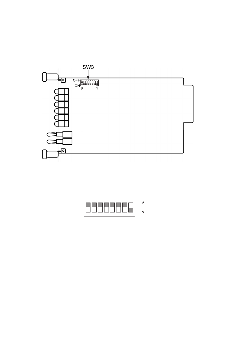
This section describes all possible hardware switch configuration. Figure 1
shows the location of the DIP switches on the top of the printed circuit board
Figure 1.
Model 2073RC top view showing location of DIP switches
Figure 2 shows the orientation of the DIP switches with respect to ON/
OFF positions.
ON
OFF
Figure 2.
ON
12345678
Close-up of DIP switches showing ON/OFF positions
7
Page 8
DIP SW3-8
DIP SW3-7
DIP SW3-6
DIP SW3-5
DIP SW3-4
DIP SW3-3
DIP SW3-2
DIP SW3-1
Note
Not Used
Not Used
ON = DTE TM Lines Disabled
OFF = DTE TM Lines Enabled
ON = FP TM Switches Disabled
OFF = FP TM Switches Enabled
ON = V54 RX Disabled
OFF = V54 RX Lines Enabled
Not Used
SW3-2
OFF
OFF
ON
ON
0 = ON, 1 = OFF
SW3-1
OFF
ON
OFF
ON
= Internal (Generated by 2073RC)
= External (From DTE)
= Network (Normal)
= Network (Campus)
Note Boldface
type
indicates a factory-default setting.
3.1 CONFIGURING THE FRONT INTERFACE CARD
Switches SW3-2 and SW3-1: Clocking Mode
Use Switch SW3 to set the system clock for the Model 2073RC. When
using two Model 2073RC together in a point-to-point application as short
range modems, set one unit for either Internal or External transmit clock
and the other unit to Network clock. When connecting directly to the
G.703 network, set the unit to Network clock.
SW3-2 SW3-1 Clocking Description
OFF OFF
OFF ON
ON OFF
ON ON
Internal (Generated by 2073RC)
External (From DTE)
Network (Normal)
Network (Campus)
8
Page 9

Switches SW3-5: Front panel switch enabled/disabled
Use Switch SW3-5 to enable or disable the Model 2073RC Test Mode
(Local Loop, Remote Digital Loop, and 511/511E patterns).
ON Front Panel Test Mode Switches Disabled
OFF Front panel Test Mode Switches Enabled
Switch SW3-6: Response to DTE Request for Local and Remote Loop
Use Switch SW3-6 to enable the Model 2073RC to enter Local Loopback
mode when pin interface (V.35 only) is raised. In the On position, the
Local Loopback may only be enabled manually by Switch SW3-6.
SW3-6 Activation Description
On Disabled Model 2073RC ignores DTE requests to enter
Local Loopback
Off Enabled Model 2073RC enters Local Loopback when the
appropriate interface pin is raised (see appendix for interf ace
pinout)
Switch SW3-4 Response to Remote digital (RDL) Loopback
Use Switch SW3-4 to enable or disable response to Remote digital Loopback by the local 2073RC when a RDL request is sent by a remote
device.
SW3-4 Description
ON RDL Response Disabled
OFF RDL Response Enabled
Switch SW3-3 Terminal (DTE) data sampled using the 2073RC
Transmit clock or External Clock (provided by V.35 DTEs only)
Use Switch SW3-3 to sample data from DTE using the 2073RC Transmit
clock (TC) or External Clock (XC))—normally Transmit clock (from
2073RC) is used.
ON TD Sampled with XC Source,
OFF TD Sampled with TC Source
9
Page 10

3.2 CONFIGURING THE REAR INTERFACE CARD
Your Model 2073RC comes with one of the following rear cards:
• The Model 1001RCM13448C (M/34/ RJ-48C)
• The Model 1001RCM11548C (DB-15/RJ-48C)
• The Model IM2RC/IA (RJ-45/10Base-T RJ-48C)
Each of these options supports one DTE interface connection and one 4-
wire line connection. Figure 3 illustrates the interface options for the
Model 2073RC Series.
Note
The 2073RC Series function card is paired with a specially
designed rear card and must not be swapped with other Patton
rear cards.
Model
1001RCM11548C
RJ-48C
DB-15 F
Figure 3.
Model 2073RC Series interface card options
Model
1001RCM13448C
RJ-48C
M/34 F
Model
IM2RC/IA
RJ-48C
Prior to installation, you will need to examine the rear card and make
sure it is properly configured for your application.
Each rear card is configured by setting straps located on the PC board.
To configure the rear cards, you must set the configuration straps.
Figure 4 shows the orientation of these straps. Each strap can either be
on pegs 1 and 2,or on pegs 2 and 3.
10
Page 11

Figure 4.
Orientation of Interface Card Straps
The following sections describe the strap locations and possible settings
for each rear card.
11
Page 12

Model 1001RCM13448C Strap Settings
Figure 5 shows the strap location for the Model 1001RCM13448C (M/34)
rear card. This strap determines whether Signal Ground and Frame
Ground will be connected.
Figure 5.
1
JB4
123
1001RCM13448C strap locations.
JB3
3
Table 1 provides an overview of interface strap functions for the rear
interface cards. Following the table overview are detailed descriptions of
each strap’s function.
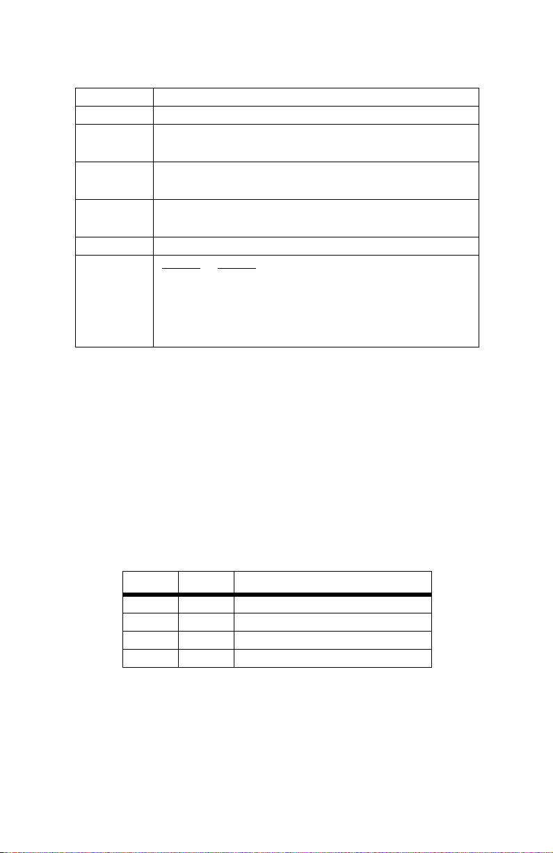
Table 1:
Interface Card Strap Summary
Strap Function Position 1&2 Position 2&3
JB3 DTE Shield (Pin A) & FRGND Connected* Open
JB4 FRGND & SGND (Pin B) Connected* Open
* Indicates default setting
12
Page 13

DTE Shield (M/34 Pin A) & FRGND (JB3).
In the connected position,
this strap links M/34 pin A & frame ground. In the open position, pin A is
disconnected from frame ground (see Table 2).
Table 2:
JB3 strap settings
Position Description
1 & 2 DTE Shield (Pin A) and FRGND Connection
2 & 3 DTE Shield (Pin A) and FRGND Not Connected
SGND & FRGND (JB4).
In the connected position, this strap links Signal
Ground and frame ground through a 100 ohm resistor. In the open position, signal ground is disconnected from frame ground (see Table 3).
Table 3:
JB4 strap settings
Position Description
1 & 2 SGND and FRGND Connected
2 & 3 SGND and FRGND Not Connected
Model 1001RCM11548C Strap Settings
Figure 6 on page 14 shows strap locations for the Model
1001RCM11548C (DB-15) rear cards. These straps determine various
grounding characteristics for the terminal interface and twisted pair lines.
JB3 and JB4 are user configurable.
13
Page 14

JB4
1
123
JB3
3
Figure 6.
1001RCM11548C strap locations.
Table 4 provides an overview of interface strap functions for the rear
interface cards. Following the table overview are detailed descriptions of
each strap’s function.
Table 4:
Interface Card Strap Summary
Strap Function Position 1&2 Position 2&3
JB3 DTE Shield (Pin1) & FRGND Connected* Open
JB4 FRGND & SGND (Pin 8) Connected* Open
* Indicates default setting
DTE Shield (DB-15 Pin 1) & FRGND (JB3).
In the connected position,
this strap links DB-15 pin 1 & frame ground. In the open position, pin 1 is
disconnected from frame ground (see Table 5).
Table 5:
JB3 strap settings
Position Description
1 & 2 DTE Shield (Pin 1) and FRGND Connected
2 & 3 DTE Shield (Pin 1) and FRGND Not Connected
14
Page 15

SGND & FRGND (JB4).
In the connected position, this strap links DB-15
pin 8 (Signal Ground) and frame ground through a 100 ohm resistor. In
the open position, pin 8 is connected directly to frame ground
(see Table 6).
Table 6:
JB4 strap settings
Position Description
1 & 2 SGND (Pin 8) and FRGND Connected through a 100 ohm resistor
2 & 3 SGND (Pin 8) and FRGND Directly Connected
Model IM2RC/IA (10Base-T Ethernet Rear Card)
There are no jumpers to set in the Model IM2RC/IA, for more information, refer to the Model IM2RC/IA user manual
The Model IM2RC/IA provides line side connections through an RJ-45
connector. Figure 7 shows rear panel options and connectors locations.
Descriptions of the 10Base-T connector LEDs follow Figure 7.
Status.
Figure 7.
Blinks yellow from one to elev en times to indicate system status.
IM2RC/A, rear panel options
Each pulse pattern is separated by a 2 second “off” period. Greater
pulse patterns have higher priority (buffer saturation has greater priority
than an empty MAC table). Valid system statuses are:
• 1 pulse = system status ok
• 2 pulses = No MAC entries in the MAC address table
• 3 pulses = Clear to send (CTS) or Carrier Detect (DCD) from base unit
are not asserted
15
Page 16

• 4 pulses = IMRC2/IAbuffer is saturated
• 5 pulses = WAN receive frame(s) too large
• 6 pulses = WAN receive frame(s) not Octet aligned
• 7 pulses = WAN receive frame(s) aborted
• 8 pulses = Detected WAN receive frame(s) with bad CRC
• 9 pulses = Detected LAN receive frame(s) too large
• 10 pulses = Detected LAN receive frame(s) not Octet aligned
• 11 pulses = Detected LAN receive frame(s) with bad CRC
After a status code is displayed eight times and the associated condition
is removed, the status code will no longer appear.
Link.
Glows green to indicate good link integrity on the 10Base-T twisted
pair line.
The RJ-45 Ethernet port on Ethernet Bridge Module is designed to con-
nect directly to a 10Base-T network. Figure 8 shows the 10Base-T RJ-45
port pin description. You may make connections up to 330 feet using
Type 4 or 5 cable.
1 (no connection)
1
2
3
4
5
6
7
8
2 (no connection)
3 (4-Wire ARX-)
4 (2-Wire TIP)/(4-Wire TX+)
5 (2-Wire RING)/(4-Wire TX-)
6 (4-Wire ARX+)
7 (no connection)
8 (no connection)
Figure 8.
Connecting to the network.
Model IMRC2/IA Ethernet Connector Pinout
The Line Interface is an 8-position keyed
modular jack configured as an RJ-48C (see. Figure 9). This interface will
connect to a 64 kbps/G.703, co-directional network running AMI line coding.
1 RX data (TIP)
1
2
3
4
5
6
7
8
2 RX data (RING)
3 (no connection)
4 TX data (TIP)
5 TX data (RING)
6 (no connection)
7 (no connection)
From network
To network
8 (no connection)
Figure 9.
64 kbps Network Interface
16
Page 17

Note
If the 2073RC is being used for private short-range modem
applications, the twisted-pair cable connected to its port will
need to be a cross-over cable.
17
Page 18

4.0 INSTALLATION
This section describes the functions of the Model 1001R14 rack chassis,
tells how to install front and rear Model 2073RC Series cards into the
chassis, and how to connect to the twisted pair interface and the serial
interface.
4.1 THE MODEL 1001R14 RACK CHASSIS
The Model 1001R14 Rack Chassis (see Figure 10) has 14 or 16 device
card slots, plus a single power supply or dual redundant power supplies.
Measuring only 3.5” high, the Model 1001R14 is designed to occupy only
2U in a 19” rack. Sturdy front handles allow the Model 1001R14 to be
extracted and transported conveniently.
Figure 10.
Model 1001R14 Rack Chassis with power supply
The Rack Power Supply
The power supply included in the Model 1001R14 rack uses the same
mid-plane architecture as the modem cards. The front card of the power
supply slides in from the front, and the rear card slides in from the rear.
They plug into one another in the middle of the rack. The front card is
then secured by thumb screws and the rear card by conventional metal
screws.
There are no user-serviceable parts in the power
supply section of the Model 1001R14 rack. Voltage setting changes and fuse replacement
should only be performed by qualified service
personnel. Contact Patton Electronics Technical
support at +1 (301) 975-1007, via our web site at
WARNING
www.patton.com, or by E-mail at
support@patton.com, for more information.
18
Page 19

Powering up your 1001R14 rack
The power supplies that come with your 1001R14 rack system are
equipped with a power entry connector on the rear power supply card.
The power supplies are hot-swappable, so you are not required to
remove the cards from the rack while applying power to the system.
Note Please refer to the Model 1001R14 Series User Manual AC and
DC Rack Mount Power Supplies for fuse and power card
replacement information.
4.2 INSTALLING THE MODEL 2073RC INTO THE CHASSIS
The Model 2073RC is comprised of a front card and a rear card. The tw o
cards meet inside the rack chassis and plug into each other by way of
mating 50 pin card edge connectors. Use the following steps as a guideline for installing each Model 2073RC into the rack chassis:
1. Slide the rear card into the back of the chassis along the metal rails
provided.
2. Secure the rear card using the metal screws provided.
3. Slide the card into the front of the chassis. It should meet the rear
card when it’s almost all the way into the chassis.
4. Push the front card gently into the card-edge receptacle of the rear
card. It should “click” into place.
5. Secure the front card using the thumb screws.
Note Since the Model 1001R14 chassis allows “hot swapping” of
cards,
it is not necessary to power down the rack
install or remove a Model 2073RC.
when you
4.3 CONNECTING TO A DTE DEVICE
The serial port on most rear interface cards are hard-wired as “DCE”
(Data Communications Equipment). The interfaces are designed to plug
into a DTE such as a terminal, PC or host computer. When making the
connection to your DTE device, use a “straight through” cable. When purchasing or constructing an interface cable, refer to the pin diagrams in
Appendix B on page 25 as guides.
4.4 CONNECTING TO A DCE DEVICE
The rear interface cards on most interface modules are hard wired as
“DCE”. Therefore, you must use a tail circuit cable when connecting to a
modem or other DCE device. When purchasing or constructing a tail circuit
interface cable, use the pin diag rams in Appendix B on page 25 as a guide .
19
Page 20

Note Pin-out requirements for tail circuit applications vary between
equipment manufacturers. If you have any questions about a
specific installation, please contact Patton Electronics Technical
Support.
4.5 CONNECTING TO A G.703/64 KBPS NETWORK
The Network Line Interface is an 8-position keyed modular jack configured as an RJ-48C (see Figure 11).
1 RX data (TIP)
1
2
3
4
5
6
7
8
2 RX data (RING)
3 (no connection)
4 TX data (TIP)
5 TX data (RING)
6 (no connection)
7 (no connection)
From network
To network
8 (no connection)
Figure 11. NetLink-E1 twisted-pair interface
Note If the 2073RC is being used for private short-range modem
applications, the twisted-pair cable connected to its port will
need to be a cross-over cable.
20
Page 21

5.0 OPERATION
Once the 2073RC is installed and configured properly it is ready to place
into operation.This section describes the function of the LED indicators,
and the use of the loopback and pattern test modes.
5.1 LED DESCRIPTIONS
The 2073RC is equipped with 12 LED indicators that monitor the status
of communication.
TD When the unit sends a one, the TXD LED is green.When it
sends a zero, the TXD LED is yellow.
RD When the unit receives a one, the RXD LED is green.When it
receives a zero, the RXD LED is yellow.
CTS Glows green to indicate that the clear-to-send signal from the
2073RC is active. Yellow indicates inactive CTS.
CD Glows green to indicate that the a carrier from the remote
modem is being received.
DTR Glows green to indicate that the DTE attached to the 2073RC
is active.
Link The Link LED lights when the unit is synchronized with the
incoming 64k/G.703 network signal.
TM The Test Mode indicator will turn on when the unit enters local
or remote loopbacks. It will also turn on when test patterns 511
or 511ER are activated.
ERR The error LED indicates various error conditions, when send-
ing a test pattern, the LED will remain lit if the unit does not
receive the identical pattern. When it receives the correct pattern, the LED will turn off.If error insertion is on, the LED will
blink once a second if everything is operating properly.
21
Page 22

Loop (V.54 & Telco) Diagnostics
The 2073RC offers two loop diagnostics for diagnosing the 2073RC and
any communication links. These tests can be activated via signals on the
serial port interface or the front panel switch.
Operating Local Loopback (LLB)
The Local Loopback (LLB) test checks the operation of the local 2073RC
and is performed separately on each unit. Any data sent to the local
2073RC in this test mode will be echoed (returned) back to the user
device (i.e.,characters typed on the k eyboard of a terminal will appear on
the terminal screen).
Figure 12. Local loopback
To perform a LL test, follow these steps:
1. The Local Loop can be initiated from the 2073RC unit either by acti-
vating the LL signal on the DTE (if you are not sure which lead is the
RDL signal, please refer to the Appendix,) or by toggling the top
front panel switch towards the label “LLB”. The Yellow TM (Test
mode) LED will turn on to indicate a successful Local loop condition.
2. Verify that the data terminal equipment is operating properly and
can be used for a test.
3. Perform a V.52 BER (bit error rate) test bit error rate (V.52) diagnos-
tics.If the BER test equipment indicates no faults, b ut the data terminal indicates a fault, follow the manufacturer’s checkout procedures
for the data terminal. Also, check the interface cable between the
terminal and the 2073RC.
22
Page 23

Operating Remote Digital Loopback (RDL)
The Remote Digital Loopback (RDL) test checks the performance of both
the local and remote 2073RC as well as a point-to-pointcommunication
link between them. Any characters sent to the remote 2073RC in this test
mode will be returned back to the originating device (i.e,characters typed
on the keyboard of the local terminal will appear on the local terminal
screen after having been passed to the remote 2073RC and looped back).
Figure 13. Remote loopback
1. The Remote Loop (V.54) can be initiated from the 2073RC unit:
either by activating the RDL signal on the DTE (if you are not sure
which lead is the RDL signal, refer to Appendix B “Interface Pin
Assignment” on page 25) or by toggling the top front panel switch
towards the label “RDL”. The Yellow TM (Test mode) LED will turn on
to indicate a successful RDL.
2. Perf orm a bit error rate test (BERT) using the internal V.52 generator
(as described in section “Bit Error Rate (V.52) Diagnostics”, turn the
Bit error rate (V.52) diagnostics on or using a separate BER Tester.If
the BER test indicates a fault, and the Remote Line Loopback test
was successful for both 2073RC you may have a problem with the
twisted pair line connection.
Bit Error Rate (V.52) Diagnostics
The 2073RC offers V.52 Bit Error Rate (BER) test patterns that can be
invoked along with the LLB and RDL tests to evaluate the unit(s) and the
communication links. When a 511 test is invoked, the 2073RC generates
a pseudo-random bit pattern of 511 bits, using a mathematical polynomial.The receiving 2073RC then decodes the received bits using the
same polynomial.If the received bits match the agreed upon pseudo-random pattern, the 2073RC and the communications link are functioning
properly . 511 or 511/E is initiated by setting the bottom front panel switch
towards the label ‘511’ or 511E” respectively. The Yellow TM (Test mode)
LED will turn on to indicate activation of the 511 or 511E test modes.
23
Page 24

APPENDIX A
MODEL 2073RC SPECIFICATIONS
A.1 TRANSMISSION FORMAT
Synchronous 64k/G.703 co-directional
A.2 TRANSMISSION LINE
Four-Wire unconditioned twisted pair
A.3 CLOCKING
Internal, External (V.35 only), or Network
A.4 INTERFACE MODULES
ITU/T V.35, ITU/T X.21, 10Base-T
A.5 LINE RATES
256 kbps
A.6 DTE RATES
64 kbps
A.7 DIAGNOSTICS
V.54 test modes for LAL and RDL; V:52 511/511E BERT pattern generator and detector.
A.8 LED STATUS INDICATORS
TD, RD, CTS, CD, DTR, Link, Error Test Mode
A.9 CONNECTORS
RJ-45 on line side; DB-25 female, M/34 female,RJ-45 female or DB-15
female depending upon which serial interface module is installed.
A.10 TEMPERATURE RANGE
32–122°F (0–50°C)
A.11 ALTITUDE
0–15,000 feet (0–4572 m)
A.12 HUMIDITY
up to 90% non-condensing
A.13 DIMENSIONS
3.5L x 2.1W x 0.78H in. (9.0L x 5.3W x 2.0H mm)
A.14 WEIGHT
1 lb. (0.45 kg)
24
Page 25

APPENDIX B
INTERFACE PIN ASSIGNMENT
V.35 Interface
(M/34F Female Connector)
(DCE Configuration)
Pin # Signal
B SGND (Signal Ground)
C RTS (Request to Send)
D CTS (Clear to Send)
E DSR (Data Set Ready)
F CD (Carrier Detect)
H DTR (Data Terminal Ready)
L LLB (Local Line Loop)
M TM (Test Mode)
N RDL (Remote Digital Loop)
P TD(Transmit Data)
R RD (Receive Data)
S TD/ (Transmit Data-B)
T RD/ (Receive Data-B)
U XTC (External Transmit Clock)
V RC(Receive Timing)
W XTC/ (External Transmit Clock)
X RC/ (Receive Timing)
Y TC(Transmit Clock-A)
AA TC/ (Transmit Clock-B)
25
Page 26

X.21 Interface
(DB-15 Female Connector)
(DTE /DCE Configuration)
Pin # Signal
1 Frame Ground
2 T (Transmit Data-A)
3 C (Control-A)
4 R (Receive Data-A)
5 I (Indication-A)
6 S (Signal Element Timing-A)
7 BT (Byte Timing-A)
8 SGND (Signal Ground)
9 T/ (Transmit Data-B)
10 C/ (Control-B)
11 R/ (Receive Data-B)
12 I/ (Indication-B)
13 S/ (Signal Element Timing-B)
14 BT/ (Byte Timing-B)
26
Page 27

Notes
_________________________________________________________
_________________________________________________________
_________________________________________________________
_________________________________________________________
_________________________________________________________
_________________________________________________________
_________________________________________________________
_________________________________________________________
_________________________________________________________
_________________________________________________________
_________________________________________________________
_________________________________________________________
_________________________________________________________
_________________________________________________________
_________________________________________________________
_________________________________________________________
_________________________________________________________
_________________________________________________________
_________________________________________________________
_________________________________________________________
_________________________________________________________
_________________________________________________________
_________________________________________________________
_________________________________________________________
27
Page 28

Notes
_________________________________________________________
_________________________________________________________
_________________________________________________________
_________________________________________________________
_________________________________________________________
_________________________________________________________
_________________________________________________________
_________________________________________________________
_________________________________________________________
_________________________________________________________
_________________________________________________________
_________________________________________________________
_________________________________________________________
_________________________________________________________
_________________________________________________________
_________________________________________________________
_________________________________________________________
_________________________________________________________
_________________________________________________________
_________________________________________________________
_________________________________________________________
_________________________________________________________
Copyright © 2003
Patton Electronics Company
All Rights Reserved.
28
 Loading...