

Page 1
USER
MANUAL
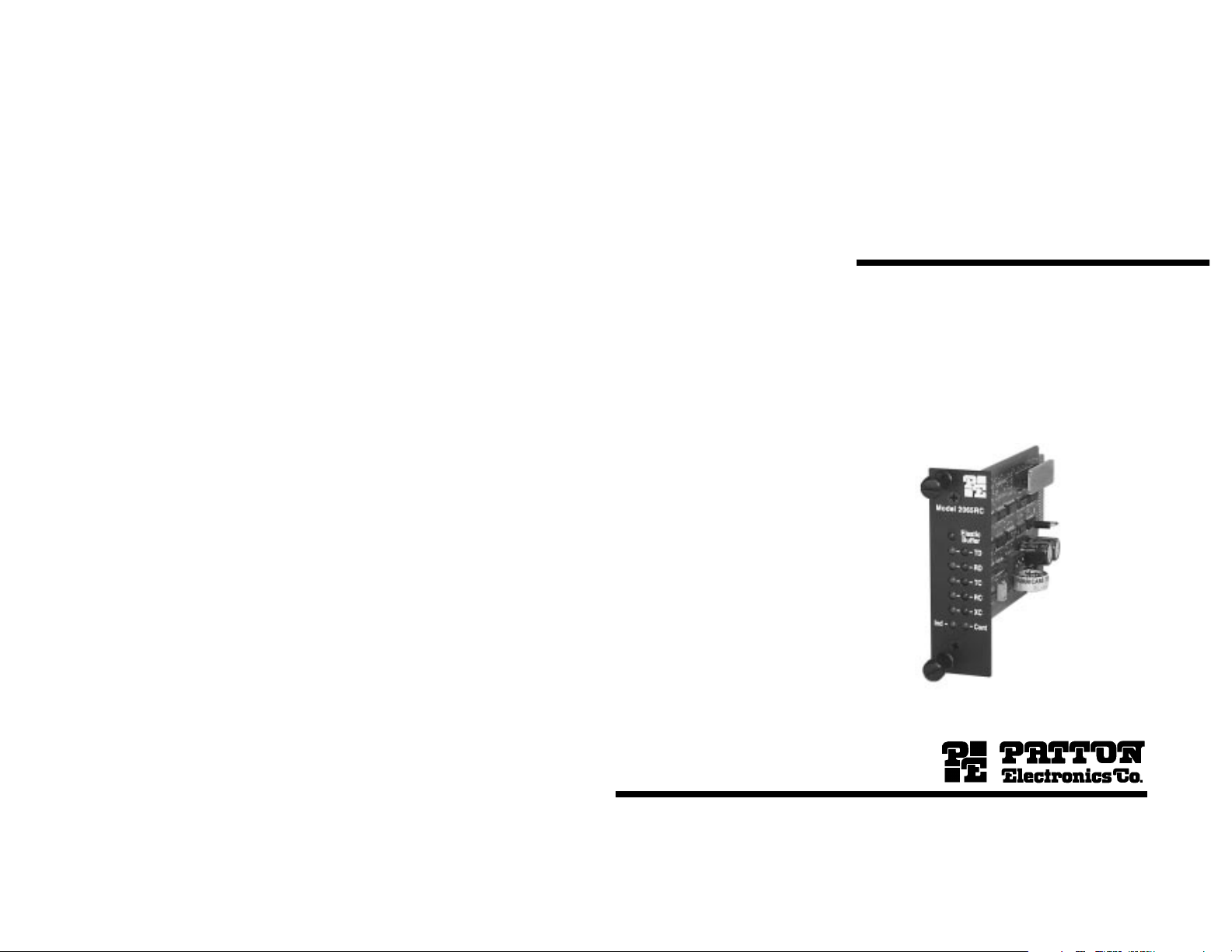
MODEL 2065/66RC
Miniature RS-232/V.35 to
X.21 Interface Converter:
Rack Mount Card
Part# 07M2065/66RC-B
Doc# 077071UB
Revised 5/24/96
SALES OFFICE
(301) 975-1000
TECHNICAL SUPPORT
(301) 975-1007
http://www.patton.com
Page 2

1.0 WARRANTY INFORMATION
Patton Electronics warrants all Model 2065/66RC components to
be free from defects, and will—at our option—repair or replace the
product should it fail within one year from the first date of shipment.
This warranty is limited to defects in workmanship or materials, and
does not cover customer damage, abuse or unauthorized modification.
If this product fails or does not perform as warranted, your sole
recourse shall be repair or replacement as described above. Under no
condition shall Patton Electronics be liable for any damages incurred
by the use of this product. These damages include, but are not limited
to, the following: lost profits, lost savings and incidental or
consequential damages arising from the use of or inability to use this
product. Patton Electronics specifically disclaims all other warranties,
expressed or implied, and the installation or use of this product shall be
deemed an acceptance of these terms by the user. I
1.1 RADIO AND TV INTERFERENCE
1.2 SERVICE
All warranty and nonwarranty repairs must be returned freight
prepaid and insured to Patton Electronics. All returns must have a
Return Materials Authorization number on the outside of the shipping
container. This number may be obtained from Patton Electronics
Technical Support: (301) 975-1007; http://www.patton.com; or,
support@patton.com.
Notice: Packages received without an RMA number will not be
accepted.
Patton Electronics' technical staff is also available to answer any
questions that might arise concerning the installation or use of your
Model 52X. Technical Service hours: 8AM to 5PM EST, Monday
through Friday.
The Model 2065/66RC generates and uses radio frequency
energy, and if not installed and used properly—that is, in strict
accordance with the manufacturer's instructions—may cause
interference to radio and television reception. The Model 2065/66RC
has been tested and found to comply with the limits for a Class A
computing device in accordance with the specifications in Subpart J of
Part 15 of FCC rules, which are designed to provide reasonable
protection from such interference in a commercial installation.
However, there is no guarantee that interference will not occur in a
particular installation.
If the Model 2065/66RC does cause interference to radio or
television reception, which can be determined by turning the power off
or disconnecting the unit, the user is encouraged to try to correct the
interference by one of the following measures: moving the computing
equipment away from the receiver, re-orienting the receiving antenna,
and/or plugging the receiving equipment into a different AC outlet (such
that the computing equipment and receiver are on different branches).
If the user detects intermittent or continuous product malfunction
due to nearby high power transmitting radio frequency equipment, the
user is advised to use data cables with an external outer shield bonded
to a metal or metalized connector, and to configure the rear card as
shown in Section 3.3 in this manual.
1.2 CE NOTICE
The CE symbol on your Patton Electronics equipment indicates
that it is in compliance with the Electromagnetic Compatibility (EMC)
directive and the Low Voltage Directive (LVD) of the Union European
(EU). A Certificate of Compliance is available by contacting Technical
Support.
2.0 GENERAL INFORMATION
Thank you for your purchase of this Patton Electronics product.
This product has been thoroughly inspected and tested and is
warranted for One Year parts and labor. If any questions during
installation or use of this product, contact Patton Electronics Technical
Support: (301) 975-1007; http://www.patton.com; or,
support@patton.com.
2.1 FEATURES
• Synchronous operation, full or half duplex
• Allows an X.21 DCE to communicate bi-directionally with an
RS-232/V.35 DCE or DTE
• V.35 data rates up to 2.048 Mbps
• RS-232 data rates up to 128 kbps
• RS-232/V.35 interface is DTE/DCE switchable
• Built-in 16 bit elastic buffers
(Model 2066RC)
(Model 2065RC)
1
2
Page 3

• Seven bi-color LED indicators on front card
• Receives timing from the X.21 DCE device
• Dual UD-26 Connectors on rear card
• Fits in Patton’s rack chassis and Cluster Boxes
3.0 CONFIGURATION
This section describes the location and orientation of the Model
2065/66RC's configuration switches and jumpers, and details all
possible settings. This section also identifies factory default
configuration settings.
2.2 DESCRIPTION
The Patton Model 2065/66RC Interface Converter Rack Card lets
an X.21 DCE to communicate bi-directionally with an RS-232/V.35 DCE
or DTE. Operating synchronously, full or half duplex, the Model
2065/66RC is protocol independent and incorporates two 16-bit elastic
buffers. For extra flexibility, the Model 2065/66RC is DTE/DCE
switchable on the RS-232/V.35 interface (the X.21 interface is
configured as a DTE). Clocking is supplied by the X.21 DCE device.
This interface converter is available in two versions: The Model
2065RC converts from X.21 to RS-232, and supports sync data rates to
128 kbps. The Model 2066RC converts from X.21 to V.35 and
supports sync data rates to 2.048 Mbps. Both versions use Patton’s
mid-plane architecture and are equipped with dual UD-26 connectors
on the rear interface card (adapter cables are available from Patton
Electronics).
The Model 2065/66RC is designed to mount in Patton’s 2U high
19” rack chassis and 2/4/8 slot Cluster Boxes. Available power
supplies include 120/230V AC and 48/24/12V DC. The Model
2065/66RC is made in the USA.
3.1 FRONT CARD CONFIGURATION
The Model 2065/66RC front card uses a single four-position DIP
switch (S1), plus a DCE/DTE strap, to configure the unit for a wide
range of applications. Figure 1 (below) shows the location of switch set
S1 and the DCE/DTE strap on the Model 2065/66RC front card. Figure
2 (below) shows the orientation of DIP switch set S1.
DCE/DTE strap
Switch S1
Figure 1. Model 2065/66RC front card, showing location of DIP switch and DCE/DTE strap.
ON
1234
Figure 2. Orientation of front card switch set S1
3.1.1 SWITCH SET S1
DIP switch set S1 has 4 switches and is used to define which
control signals will be passed between the two interfaces. Depending
upon the setting of the DCE/DTE strap, the function of the four switches
3
4
OFF
Page 4

will change. The summary table below describes DIP switch S1
settings, including factory defaults.
3.1.2 SETTING THE DCE/DTE STRAP
The RS-232/V.35 interface on the Model 2065/66RC is DCE/DTE
switchable. The default setting is “RS-232/V.35 DCE to X.21 DTE”,
based upon how the converter sees its
own
orientation. When
S1 SUMMARY TABLE
Position RS-232/V.35 = DCE RS-232/V.35 = DTE
ON = “CD from the RS-232/V.35
DCE must be ON in order for the
X.21 CONTROL signal
to turn ON”
OFF = “CD from the RS-232/V.35
DCE has no effect on the
CONTROL signal going to
the X.21 DCE”
S1-1
ON = “DTR from the RS232/V.35 DTE must be ON in
order for the X.21 CONTROL
signal to turn ON”
OFF = “DTR from the RS-
232/V.35 DTE has no effect on
the CONTROL signal going to
the X.21 DCE”
configured this way, the Model 2065/66RC will want to connect to an
RS-232/V.35 DTE device. Changing the DCE/DTE strap orientation will
enable the Model 2065/66RC to connect to an RS-232/V.35 DCE
device. (Note: the X.21 port on the Model 2065/66RC is
as a DTE and is
not
switchable. This port always wants to connect to
always
wired
an X.21 DCE device.)
The RS-232/V.35 DCE/DTE strap is located near the rear of the
Model 2065/66RC front card’s PC board (see Figure 3, below). The
arrows on the top of the strap indicate the configuration of the Model
2065/66RC. For example, if the “DCE” arrows are pointing toward the
edge of the card (up), then the Model 2065/66RC is wired as a DCE
and wants to connect to an RS-232/V.35 DTE device.
➞
➞
DCE
DTE
➞
➞
ON = “RTS from the RS-232/V.35
DTE must be ON in order for the
S1-2
S1-3
S1-4
Note: Bold indicates factory default setting
X.21 CONTROL signal
to turn ON”
OFF = “RTS from the RS-
232/V.35 DTE has no effect on
the CONTROL signal going to
the X.21 DCE”
(not applicable)
Set to OFF
(not applicable)
Set to ON
ON = “CTS from the RS-232/V.35
DCE must be ON in order for the
X.21 CONTROL signal
to turn ON”
OFF = “CTS from the RS-
232/V.35 DCE has no effect on
the CONTROL signal going to
the X.21 DCE”
ON = “DSR from the RS-232/V.35
DCE must be ON in order for the
X.21 CONTROL signal
to turn ON”
OFF = “DSR from the RS-
232/V.35 DCE has no effect on
the CONTROL signal going to
the X.21 DCE”
ON = “INDICATION from the
X.21 DCE controls RTS and DTR
going to the RS-232/V.35 DCE”
OFF = “INDICATION from the
X.21 DCE controls RTS only
going to the RS-232/V.35 DCE.
DTR is always ON”
Figure 3. Model 2065/66RC front card, with close-up of DCE/DTE strap.
To change the DCE/DTE orientation of the Model 2065/66RC’s RS232/V.35 interface, simply remove the strap and rotate it 180
0
, so that
the appropriate arrows are pointing toward the edge of the card.
5
6
Page 5

3.3 REAR CARD CONFIGURATION
The rear interface card for the Model 2065/66RC is equipped with
two female UD-26 connectors: one for each port. This card has one
configuration jumper (JB4). Figure 4 (below) shows the location of this
jumper on the PC board.
JB4
(peg 1 toward
bottom of card,
peg 3 toward top
of card)
Figure 4. Rear card jumper location
As Figure 5 (below) shows, jumper JB4 has two possible
positions: strap covering posts 1 & 2, or strap covering posts 2 & 3.
The orientation of the jumper with respect to pin positions is shown in
Figure 4 (above).
4.0 INSTALLATION
This section describes the functions of the Model 1000R16P rack
chassis, tells how to install front and rear Model 2065/66RC cards into
the chassis and provides diagrams for wiring up the interface
connections correctly.
4.1 THE MODEL 1000R16P RACK CHASSIS
The 1000R16P Rack Chassis (shown in Figure 6, below) has
sixteen short range modem card slots, plus its own power supply.
Measuring only 3.5" high, the 100016RP is designed to occupy only 2U
in a 19" rack. Sturdy front handles allow the 1000R16P to be extracted
and transported conveniently.
Figure 6. Model 1000R16P Rack Chassis with Power Supply
Figure 5. Possible function card strap positions
SGND & FRGND (JB4)
In the connected position, this jumper links UD-26 pin 7 (Signal
Ground) and frame ground. In the open position, pin 1 is “lifted” from
frame ground.
JB4
Position 1&2 = SGND (UD-26 pin 7)
and FRGND Connected
Position 2&3 = SGND (UD-26 pin 7)
and FRGND Not Connected
7
4.1.1 THE RACK POWER SUPPLY
The power supply included in the Model 1000R16P rack uses the
same mid-plane architecture as the modem cards. The front card of
the power supply slides in from the front, and the rear card slides in
from the rear. They plug into one another in the middle of the rack.
The front card is then secured by spring loaded thumb screws and the
rear card by conventional metal screws.
WARNING! There are no user-serviceable parts in the
power supply section of the Model 2065/66RC. Voltage
setting changes and fuse replacement should only be
performed by qualified service personnel. Contact Patton
Electronics Technical support at (301)975-1007 for more
information.
(continued)
8
Page 6

Switching the Power Supply On and Off
4.3 DCE/DTE CONNECTION
The power switch is located on the front panel. When plugged in
and switched on, a red front panel LED will glow. Since the Model
1000R16P is a "hot swappable" rack,
to be installed before switching on the power supply
may be switched off at any time without harming the installed cards.
4.2 INSTALLING THE MODEL 2065/66RC INTO THE CHASSIS
The Model 2065/66RC is comprised of a front Function card and a
rear Interface card. The two cards connect in the rack chassis via
mating 50 pin card edge connectors. Use the following steps as a
guideline for installing each Model 2065/66RC into the Model
1000R16P rack chassis:
1. Slide the rear Interface card into the back of the chassis along the
metal rails.
2. Secure the rear card using the metal screws provided.
3. Slide the Function card into the front of the chassis. It should
meet the rear card when it's almost all the way into the
chassis.
4. Push the front card
card. It should "click" into place.
5. Secure the front card using the spring loaded thumb screws.
gently
it is not necessary for any cards
. The power supply
into the card-edge receptacle of the rear
Note: Since the Model 1000R16P chassis allows "hot swapping" of
cards, it is not necessary to power down the rack when you install or
remove a Model 2065/66RC.
The Model 2065/66RC rear card has two UD-26 connectors,
labeled “A1” and “B1” (see figure 7, below). Port A1 connects to the
RS-232 device (Model 2065RC) or the V.35 device (Model 2066RC).
Port B1 connects to the X.21 device in all cases. Port A1 may be
configured as either a DCE or DTE. Port B1 is always configured
as a DTE.
A1 B1
Figure 7. Model 2065/2066RC rear interface card, showing connectors
To connect computing devices to ports A1 and B1 on the Model
2065/2066RC, follow these instructions:
1. Configure the Model 2065/2066RC for your specific application
according to the instructions in Section 3.0 of this manual.
2. Connect computing devices to the Model 2065/2066RC using
multipair adapter cables (see Appendix B for a list of custom
adapter cables available from Patton Electronics). In all cases, the
X.21 DCE must supply the system timing, and the RS-232/V.35
device must accept external clock. The wiring of your adapter
cables should support this requirement.
Notice! Any terminal cable connected to the Model
2065/66RC must be shielded cable, and the outer shield
must be 360 degree bonded–at both ends–to a metal or
metalized backshell.
9
10
Page 7

5.0 OPERATION
Once you have configured each Model 2065/66RC and connected
the cables, you are ready to operate the unit. This section describes
the LED status monitors, clocking requirements and the power-up
procedure.
5.1 LED STATUS MONITORS
The Model 2065/66RC features seven front panel LEDs that
indicate the condition of the modem and communication link. Figure 8
(below) shows the positions of the LEDs, and the bullets describe their
functions.
Model 2066RC
Elastic
Buffer
TD
RD
TC
RC
XC
ContInd
Figure 8. The Model 2065/66RC front panel, showing LED positions
If the DCE/DTE strap is set for “Converter = DTE”, then receive
data is an input to the converter. Red indicates a mark or idle
state. Green indicates a space or active state.
• TC (Transmit Clock) - indicates status of transmit clock at RS232/V.35 interface. If the DCE/DTE strap is set for “Converter =
DCE”, then transmit clock is an output from the converter. If the
DCE/DTE strap is set for “Converter = DTE”, then transmit clock is
an input to the converter. Red indicates a mark or idle state.
Green indicates a space or active state.
• RC (Receive Clock) - indicates status of receive clock at RS232/V.35 interface. If the DCE/DTE strap is set for “Converter =
DCE”, then receive clock is an output from the converter. If the
DCE/DTE strap is set for “Converter = DTE”, then receive clock is
an input to the converter. Red indicates a mark or idle state.
Green indicates a space or active state.
• XC (External Clock) - indicates status of external clock at RS232/V.35 interface. If the DCE/DTE strap is set for “Converter =
DCE”, then external clock is an input to the converter (see Note
1
).
If the DCE/DTE strap is set for “Converter = DTE”, then external
clock is an output from the converter (see Note2). Red indicates a
mark or idle state. Green indicates a space or active state.
Note1: When configured this way, an external clock output from the
RS-232/V.35 DTE to the converter is not required.
Note2: When configured this way, the external clock output from the
converter must be used by the RS-232/V.35 DCE as the clock source.
• Elastic Buffer - monitors elastic buffer status, and operates only
when the Model 2065/66RC’s RS-232/V.35 port is configured as a
DTE (i.e. the converter is connected between two DCE devices).
When configured in this manner, the two internal 16-bit elastic
buffers are enabled. If either of these buffers becomes full or
empty (due to clock loss or slip), the LED will briefly glow red to
indicate data loss. The buffer will then reset to half-full and the
LED will stop glowing. When the Model 2065/66RC’s RS-232/V.35
port is configured as a DTE, this LED has no function.
• TD (Transmit Data) - indicates status of transmit data at RS232/V.35 interface. If the DCE/DTE strap is set for “Converter =
DCE”, then transmit data is an input to the converter. If the
DCE/DTE strap is set for “Converter = DTE”, then transmit data is
an output from the converter. Red indicates a mark or idle state.
Green indicates a space or active state.
• RD (Receive Data) - indicates status of receive data at RS232/V.35 interface. If the DCE/DTE strap is set for “Converter =
DCE”, then receive data is an output from the converter.
(continued)
11
• IND (Indicate) - glows green when INDICATE from the X.21 DCE
is active.
• CONT (Control) - glows green when CONTROL to the X.21 DCE
is active.
5.2 CLOCKING
always
The Model 2065/66RC
connects to an X.21 DCE device. In
all applications the X.21 DCE must supply the system timing.
Consequently, the RS-232/V.35 device (DCE or DTE)
must
be
configured to accept an external clock input. Any other equipment
clock settings will likely cause clock slip and/or data loss.
5.2 POWER-UP
There is no power switch on the Model 2065/66RC: Power is
automatically applied to the 2065/66RC when its card-edge connector
touches the chassis' mid-plane socket, or when the chassis' power is
turned on.
Note: The 2065/66RC is a "hot swappable" card—it will not
be damaged by plugging it in or removing it while the rack is powered
up.
12
Page 8

APPENDIX A
MODEL 2065/66RC SPECIFICATIONS
Transmission Format: Synchronous
External Interface: Dual UD-26 high density connectors
Internal Interface: Connection to Model 1000R16P rack
chassis via male card edge
Electrical Interface: X.21 - EIA RS-422/V.11 compatible;
RS-232 - RS-232/V.24 compatible; V.35 data
and clock signals: receivers - V.35
compliant, drivers - 0.55V differential signal;
V.35 control signals - RS-232/V.24
compatible
Data Rates: Model 2065RC (RS-232), up to 128 kbps;
Model 2066RC (V.35), up to 2.048 Mbps.
Clocking: RS-232/V.35 DCE or DTE receiving timing
from an X.21 DCE device
DCE to DCE buffering: Dual 16-bit buffers for full duplex operation -
set to 8 bits in case of underflow or overflow.
Controls: Switchable, custom control settings (see
Section 3.0)
Indicators: Bi-level LED indicators for TD, RD, TC, RC
and XC; single green indicator for
INDICATION and CONTROL; single red
indicator for elastic buffer status.
Power Supply: Rack-mount power supply is switchable
between 120V and 240V AC; chassis
supplies 10V AC to the Model
2065/2066RC, typical consumption is 1.2
watts
Temperature: 0-50°C / 32-122°F
Humidity: 5-95%, noncondensing
Dimensions: 0.95”w x 3.1”h x 5.4”l
APPENDIX B
PATTON MODEL 2065/66RC FACTORY REPLACEMENT PARTS
The Patton Model 2065/66RC rack system features interchangeable
rear half cards, power cords/fuses for international various operating
environments and other user-replaceable parts. Model numbers and
descriptions for these parts are listed below:
Patton Model # Description
2065-26M/15F.....................Cable, 6 ft, UD-26M to DB-15F
2065-26M/15M....................Cable, 6 ft, UD-26M to DB-15M
2065-26M/25F.....................Cable, 6 ft, UD-26M to DB-25F
2065-26M/25M....................Cable, 6 ft, UD-26M to DB-25M
2065-26M/34F.....................Cable, 6 ft, UD-26M to M/34F
2065-26M/34M....................Cable, 6 ft, UD-26M to M/34M
1000RPEM..........................120/240V Rear Power Entry Module
1000RPSM-1.......................120/240V Front Power Supply Module
1000RPEM-DC ...................DC Rear Power Entry Module
1000RPSM-48A..................48V Front Power Supply Module
0805US...............................American Power Cord
0805EUR.............................European Power Cord CEE 7
0805EURP..........................Europlug Power Cord CEE 7/16
0805UK...............................United Kingdom Power Cord
0805AUS.............................Australia/New Zealand Power Cord
0805DEN.............................Denmark Power Cord
0805FR ...............................France/Belgium Power Cord
0805IN.................................India Power Cord
0805IS.................................Israel Power Cord
0805JAP..............................Japan Power Cord
0805SW ..............................Switzerland Power Cord
0516FPB1...........................Single Width Blank Front Panel
0516FPB4...........................4-Wide Blank Front Panel
0516RPB1...........................Single Width Blank Rear Panel
0516RPB4...........................4-Wide Blank Rear Panel
Copyright ©
Patton Electronics Company
All Rights Reserved
13
056S1..................................Set of 16 #4 pan head screws/washers
14
Page 9

APPENDIX C
MODEL 2065/66RC INTERFACE SETTINGS AND ORIENTATION
MODEL 2065/66RC X.21 INTERFACE (DTE)
APPENDIX D
PATTON MODEL 2065/66RC BLOCK DIAGRAM
Not Used -26
Not Used -25
Not Used -24
Not Used -23
Not Used -22
Not Used -21
Not Used -20
Control-b (C-b) -19
Not Used -18
Not Used -17
Receive-b (R-b) -16
Sgnl Elmt Tmg (a) (S-a) -15
Transmit (b) (T-b) -14
MODEL 2065RC RS-232 INTERFACE
Not Used -26
Not Used -25
External Clock (XC) -24
Not Used -23
Not Used -22
Not Used -21
Data Term Ready (DTR) -20
Not Used -19
Not Used -18
Receive Clock (RC) -17
Not Used -16
Transmit Clock (TC) -15
Not Used -14
13- Not Used
12- (S-b) Sgnl Elmt Tmg (b)
11- Not Used
10- (I-b) Indication (b)
9- Not Used
8- (I-a) Indication (a)
7- (SG) Signal Ground
6- Not Used
5- Not Used
4- (C-a) Control (a)
3- (R-a) Receive (a)
2- (T-a) Transmit (a)
1- (FG) Frame Ground
13- Not Used
12- Not Used
11- Not Used
10- Not Used
9- Not Used
8- (CD) Carrier Detect
7- (SG) Signal Ground
6- (DSR) Data Set Ready
5- (CTS) Clear to Send
4- (RTS) Request to Send
3- (RD) Receive Data
2- (TD) Transmit Data
1- (FG) Frame Ground
MODEL 2066RCV.35 INTERFACE
Not Used -26
Not Used -25
External Clock (a) (XC-a) -24
Not Used -23
Not Used -22
Not Used -21
Data Term Ready (DTR) -20
Not Used -19
Not Used -18
Receive Clock (a) (RC-a) -17
Receive Data (b) (RD-b) -16
Trans Clock (a) (TC-a) -15
Transmit Data (b) (TD-b) -14
13- Not Used
12- (TC-b) Trans Clock (b)
11- (XC-b) Ext Clock (b)
10- Not Used
9- (RC-b) Receive Clock (b)
8- (CD) Carrier Detect
7- (SG) Signal Ground
6- (DSR) Data Set Ready
5- (CTS) Clear to Send
4- (RTS) Request to Send
3- (RD-a) Receive Data (a)
2- (TD-a) Transmit Data (a)
1- (FG) Frame Ground
15
16
 Loading...