

Page 1

USER
MANUAL
MODEL 2042 Series
RS-530 to HSSI
Interface Converter
SALES OFFICE
(301) 975-1000
TECHNICAL SUPPORT
(301) 975-1007
http://www.patton.com
Part# 07M2042-UM
Doc# 07722U2-001,
Rev. D
Revised 10/25/06
An ISO-9001
Certified Company
Copyright © 2006
Patton Electronics Company
All Rights Reserved
CERTIFIED
Page 2

1
TABLE OF CONTENTS
SECTION PAGE
1.0 Warranty Information ............................................................2
1.1 Radio and TV Interference
1.2. CE Notice
1.3 Service Information
2.0 General Information ..............................................................4
2.1 Features
2.2 Description
3.0 Configuration ........................................................................5
3.1 Configuration Switches (Model 2042MC-MT)
3.2 Configuration Switches (Model 2042MT-MC)
4.0 Installation..............................................................................10
4.1 2042MC-MT Connection
4.2 2042MT-MC Connection
4.3 AC Power Connection
4.4 DC Power Connection
5.0 Operation ..............................................................................12
5.1 Back Panel LED Status Monitors
5.2 Test Modes
5.2.1 Local Loopback (LL)
5.2.2 Remote Digital Loopback (RL)
Appendix A - Specification ............................................................15
Appendix B - Factory Replacement Parts and Accessories ........16
Appendix C - Interface Pin Assignments17
Appendix D - 2042MT-MC Block Diagram....................................
19
Appendix E - 2042MC-MT Block Diagram....................................20
2
1.0 WARRANTY INFORMATION
Patton Electronics warrants all Model 2042 components to be
free from defects, and will—at our option—repair or replace the product should it fail within one year from the first date of shipment.
This warranty is limited to defects in workmanship or materials,
and does not cover customer damage, abuse or unauthorized modification. If this product fails or does not perform as warranted, your sole
recourse shall be repair or replacement as described above. Under no
condition shall Patton Electronics be liable for any damages incurred
by the use of this product. These damages include, but are not limited
to, the following: lost profits, lost savings and incidental or consequential damages arising from the use of or inability to use this product.
Patton Electronics specifically disclaims all other warranties,
expressed or implied, and the installation or use of this product shall
be deemed an acceptance of these terms by the user.
1.1 RADIO AND TV INTERFERENCE
The Model 2042 generates and uses radio frequency energy, and
if not installed and used properly—that is, in strict accordance with the
manufacturer's instructions—may cause interference to radio and television reception. The Model 2042 has been tested and found to comply with the limits for a Class Acomputing device in accordance with
the specifications in Subpart J of Part 15 of FCC rules, which are
designed to provide reasonable protection from such interference in a
commercial installation. However, there is no guarantee that interference will not occur in a particular installation. If the Model 2042 does
cause interference to radio or television reception, which can be determined by disconnecting the Model 2042, the user is encouraged to try
to correct the interference by one or more of the following measures:
moving the computing equipment away from the receiver, re-orienting
the receiving antenna and/or plugging the receiving equipment into a
different AC outlet (such that the computing equipment and receiver
are on different branches).This device must accept any interference
received, including interference that may cause undesired operation.
1.2 CE NOTICE
The CE symbol on your Patton Electronics equipment indicates
that it is in compliance with the Electromagnetic Compatibility (EMC)
directive and the Low Voltage Directive (LVD) of the Union European
(EU). ACertificate of Compliance is available by contacting Technical
Support.
WARNING: To Users of Digital Apparatus in Canada:
This Class Adigital apparatus meets all requirements of the
Canadian interference-causing equipment regulations.
Page 3

3
1.3 SERVICE
All warranty and nonwarranty repairs must be returned freight prepaid and insured to Patton Electronics. All returns must have a Return
Materials Authorization number on the outside of the shipping container. This number may be obtained from Patton Electronics Technical
Service at:
Tel: (301) 975-1007
Email: support@patton.com
www: http://www.patton.com
Patton Electronics' technical staff is also available to answer any
questions that might arise concerning the installation or use of your
Model 2042. Technical Service hours: 8AM to 5PM EST, Monday
through Friday.
NOTE: Packages received without an RMA number will not be
accepted.
4
2.0 GENERAL INFORMATION
Thank you for your purchase of this Patton Electronics product. It
has been thoroughly inspected and tested and is warranted for One
Year for parts and labor. If you have any questions about this product,
please call Patton Electronics Technical Support at (301) 975-1007.
2.1 FEATURES
• Bi-directionally converts RS-530 to HSSI.
• Supports synchronous data rates up to 10Mbps.
• Transparent to synchronous protocol.
• DB-25 and HD-50 connectors with integral 6-foot (1.8m) cable.
• Two versions available:
Model 2042MC-MT: Connects RS-530 (DTE) to HSSI (DCE)
Model 2042MT-MC: Connects 530 (DCE) to HSSI (DTE)
• Internal synchronization circuit enables high speed connections
• Externally AC powered.
• Made in the U.S.A.
2.2 DESCRIPTION
The Model 2042 is a RS-530 to High Speed Serial Interface
(HSSI) converter. It allows a HSSI (HD-50) device to communicate bidirectionally with a RS-530 device at synchronous data rates up to
10Mbps. The Model 2042 supports all HSSI co-directional timing patterns, 2 loopback modes (local and remote line), full duplex data and
control signals.
The Model 2042 is available in several versions: The Model
2042MT-MC lets a RS-530 DCE device communicate with a HSSI DTE
device. The Model 2042MC-MT lets a RS-530 DTE device communicate with a HSSI DCE device.
All versions are equipped with a male DB-25 connector on the
converter end, and a male HD-50 on the end of a 6-foot (1.8 m) cable.
Other connector genders and cable lengths are available on a custom
basis. Power is supplied to the Model 2042 by an external desktop AC
transformer.
Page 4
5
3.0 CONFIGURATION
The Model 2042 is easy to install and is ruggedly designed for
excellent reliability. The following instructions will help you set up and
install the Model 2042 properly.
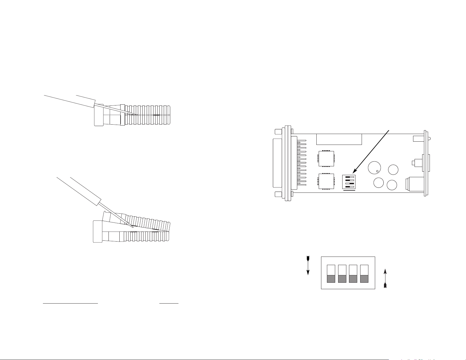
To use the Patton Model 2042, you must first configure the unit for
your application. To do so, first open the case by inserting a flat head
screw driver into an open slot on either side of the case, as in Figure 1.
Twist the screw driver head slightly and the top half of the case
will separate from the lower half, as in Figure 2. You now have access
to the internal switches used to configure the unit.
After opening the case, please refer to the section that pertains to
your unit for configuration details:
Patton Model Number Section
Model 2042MC-MT....................................................3.1
Model 2042MT-MC....................................................3.2
To close the case, fit the 2 halves together snugly and snap them
back in place.
Figure 1: Using a Small Screw Driver to Open the Model 2042 Case
Figure 2: Using a Small Screw Driver to Open the Model 2042 Case
6
3.1 CONFIGURATION SWITCHES (MODEL 2042MC-MT)
The Model 2042MC-MT has miniature DIP switches that you may
use to configure the units. Each Model 2042MC-MT is factory configured as DCE on the RS-530 end, and DTE on the HSSI end.
Therefore, the RS-530 end “wants” to plug directly into a DTE device.
Conversely, the HSSI end of the converter “wants” to plug directly into
DCE.
Please use this section to configure the internal DIP switches so
that the unit will work properly in your application. Figure 3 shows the
position of the DIP switches on the top side of the PC board.
Figure 4 shows the orientation of the switches on DIP Switches S1
through S4 with respect to ON/OFF positions. The default settings for
DIP Switch S1 are shown in the table 1 on page 6. Detailed descriptions of each switch follow the table.
Figure 3. The Model 2042MC-MT Assembly Drawing
Figure 4. Close-up of DIP Switches Showing “ON” and “OFF” Positions
1234
ON
OFF
ON
DIP Switches S1 - S4
ON
OFF
1234
Page 5

7
Switches S1 and S2: Clock Source
The setting for Switches S1 and S2 determines the source of the
HSSI Terminal Timing (TT) for the 2042MC-MT. With Switch S1 On
and S2 Off, the Model 2042MC-MT derives the HSSI Terminal Timing
from the ST signal provided by the HSSI DCE. With Switch S1 Off,
and S2 On, the RS-530 DTE provides TT to the HSSI DCE.
S1 S2 Description
Off Off Not a Valid Setting
Off On Terminal Timing Supplied by RS-530 DTE
device
On Off Terminal Timing supplied by HSSI ST signal
On On Not a Valid Setting
Switches S3 and S4: Synchronization Method
Switches S3 and S4 allow the Model 2042MC-MT to compensate
for timing delays when transmitting HSSI data at high speeds (greater
than 2.5 Mbps). At high bit rates, set Switch S3 On and Switch S4 Off.
In this setting, the RS-530 data will be synchronized to the SD timing
signal before conversion to HSSI. At lower bit rates (less than 2.5
Mbps), set Switch S3 Off and S4 On. In this setting, the RS-530 data
bypasses the synchronization circuit and is passed straight through to
the HSSI DCE.
S3
S-4 Description
Off Off Not a Valid Setting
Off On Data Skips Sync Circuit
On Off Data passes through sync circuit.
On On Not a Valid Setting
2042MC-MT DIP SWITCH SUMMARY TABLE
Position Function Factory Default
S1 Clock Source On
S2 Clock Source Off
S3 Sync Method Off
S4 Sync Method On
}
}
HSSI ST
Signal
Bypass
Sync Circuit
8
3.2 CONFIGURATION SWITCHES (MODEL 2042MT-MC)
The Model 2042MT-MC has miniature DIP switches that you may
use to configure the units. Each Model 2042MT-MC is factory configured as DTE on the RS-530 end, and DCE on the HSSI end.
Therefore, the RS-530 end “wants” to plug directly into a DCE device.
Conversely, the HSSI end of the converter “wants” to plug directly into
DTE.
Please use this section to configure the internal DIP switches so
that the unit will work properly in your application. Figure 5 shows the
position of the DIP switches on the top side of the PC board.
Figure 6 shows the orientation of the Switches on DIP Switches S1
through S4 with respect to ON/OFF positions. The default settings for
DIP switch S1 are shown in the table on page . Detailed descriptions
of each switch follow the table.
Figure 5. The Model 2042MT-MC Assembly Drawing
Figure 6. Close-up of DIP Switches Showing “ON” and “OFF” Positions
1234
ON
OFF
ON
DIP Switches S1 - S4
ON
OFF
1234
Page 6

9
Switches S1 and S2: Gapped Clock
Switches S1 and S2 allow the Model 2042MT-MC to generate a
HSSI gapped clock. Gapped clocking is a method of flow control in
which data flow is interrupted by an idle (gapped) clock signal. In this
mode, the Model 2042MT-MC will gap the ST clock to the HSSI DTE
whenever the RS-530 CTS signal is de-asserted. In the ‘No Gapped
Clock’ setting, the RS-530 clock passes through with only a level
change.
S1 S2 Description
Off Off Not a Valid Setting
Off On Gapped Clock
On Off No Gapped Clock
On On Not a Valid Setting
Switches S3 and S4: Synchronization Method
Switches S3 and S4 allow the Model 2042MT-MC to compensate
for timing delays when transmitting HSSI data at high speeds (greater
than 2.5 Mbps). At high bit rates, set Switch S3 On and Switch S4 Off.
In this setting, the HSSI SD signal will be synchronized to the SD timing signal before conversion to RS-530. At lower bit rates (less than
2.5 Mbps), set Switch S3 Off and S4 On. In this setting, the RS-530
data bypasses the synchronization circuit and is passed straight
through to the HSSI DTE.
S3 S4 Description
Off Off Not a Valid Setting
Off On Data Skips Sync Circuit
On Off Data passes through sync circuit.
Off Off Not a Valid Setting
2042MT-MC DIP SWITCH SUMMARY TABLE
Position Function Factory Default
S1 Gapped Clock On
S2 Gapped Clock Off
S3 Sync Method Off
S4 Sync Method On
}
}
No Gapped
Clock
Bypass
Sync Circuit
10
4.0 INSTALLATION
The Model 2042 is designed to connect RS-530 devices to
devices which employ the HSSI interface standard. This section
describes how to install the units.
4.1 2042MC-MT CONNECTION
The Model 2042MC-MT is designed to connect an RS-530 DTE
device to an HSSI DCE device. In this application, the DB-25 (RS-
530) and HD-50 (HSSI) male connectors of the Model 2042MC-MT
may connect directly to their respective equipment ports, or they may
connect via a short “straight-through” cable (See Appendix C for
Interface Pin Assignments). Figure 7 below illustrates the proper connection of the Model 2042MC-MT.
4.2 2042MT-MC CONNECTION
The Model 2042MT-MC is designed to connect an RS-530 DCE
device to an HSSI DTE device. In this application, the DB-25 (RS-530)
and HD-50 (HSSI) male connectors of the Model 2042MT-MC may
connect directly to their respective equipment ports, or they may connect via a short “straight-through” cable (See Appendix C for Interface
Pin Assignments). Figure 8 below illustrates the proper connection of
the Model 2042MT-MC.
Figure 7. A Common RS-530 DTE to HSSI DCE Installation
Figure 8. ACommon HSSI DTE to RS-530 DCE Installation
Router with HSSI
Interface
(DTE)
T1/T3 DSU with
RS-530 Interface
(DCE)
Model 2042MT-MC
Model 2042MC-MT
T1/E1 CSU/DSU with
HSSI Interface
(DCE)
T1/E1 Router with
RS-53 Interface
(DTE)
Page 7

11
4.3 AC POWER CONNECTION
The Model 2042 uses a 5VDC, 2A universal input, power supply
that is equipped with a male IEC-320 power entry connector and supports a voltage range of 100-240VAC. This transformer connects to
the Model 2042 by means of a cannon jack on the rear panel. There
are a variety of domestic and international power cords available for
the power entry (See Appendix B). The Model 2042 is powered-up as
soon as it is plugged into an AC outlet–there is no power switch.
4.4 DC POWER CONNECTION
The 36-60 VDC DC to DC adapter is supplied with the DC version
of the Model 2042. The black and red leads plug into a DC source
(nominal 48VDC) and the barrel power connector plugs into the barrel
power supply jack on the 2042
.
12
5.0 OPERATION
Once you have configured the Model 2042 properly (see Section
3.0) and have correctly connected DTE, DCE and power (see Section
4.0), you are ready to operate the unit. This section describes the LED
status monitors and loopback test modes.
5.1 BACK PANEL LED STATUS MONITORS
The Model 2042 features two LEDs that are located on the back
panel. Figure 9 below shows the positions of the LEDs. Following
Figure 9 is a description of each LED.
Status Glows green to indicate that both DTR (from the DTE
device) and DSR (from the DCE device) are active.
This LED will not be illuminated whenever one of the
two signals are inactive.
Test Mode Glows green to indicate that either one or both of the
test modes are active (See Section 5.2 for a description
of the test modes).
5.2 TEST MODES
The Model 2042 supports two loopback modes that may be used
to evaluate the condition of the communication links. These modes,
(Local Loopback (LL) and Remote Loopback (RL), are always initiated
by the signals on the DTE device (See Figure 10). This section
describes both loopback modes.
Figure 9. Model 2042 Rear Panel
External Power Jack
HSSI Cable
Test Mode LED
Status LED
NOTE: HSSI supports a third loopback mode: Local Digital
Loopback (LDL). However, RS-530 does not support this mode.
In order to use LDL, the RS-530 device must be programmed to
respond according the the HSSI specification for LDL (See
TIA/EIA-613, Section 6.2.1 Local Digital Loopback (Loop A).
To Power
Supply Jack
Barrel power connector
S/N: G01234567890
MADE IN CHINA BY SUNNY
MODEL : SYD1106-0505
INPUT : 36-60V 0.2A MAX
OUTPUT : +5V 1.0A
OUTPUT POWER : 5W MAX
SWITCHING POWER SUPPLY
-Vin
+Vin
To -48VDC
Source
Black lead (-V)
Red lead (+V)
Page 8

14
5.2.2 Remote Digital Loopback (RL)
The Remote Loopback (RL) test checks the performance of the
link between the DTE device and the DCE as well as the link between
the local and remote DCE devices. Any characters sent from the DTE
in this test mode will be sent to the local DCE, which will send the data
to the remote DCE. The remote DCE should return the data back
through the entire communication link and finally, to the DTE. To perform a RL test, follow these steps:
A. Activate RL from the DTE device. This may be done either by
raising pin N on the RS-530 interface (if the RS-530 device is
DTE), or by activating Local Loopback from the HSSI interface (if
the HSSI device is the DTE). The “test” LED should be lit.
B. Perform a BER (bit error rate) test from the DTE.
C. If the BER test equipment indicates a fault, and the Local
Loopback test was successful, you may have a problem with the
cable between the DCE devices.
NOTE: The Model 2042 simply converts and passes the data
through the communication link. The DCEs must be configured
to perform to the appropriate loopback diagnostic.
13
5.2.1 Local Loopback (LL)
The Local Loopback (LL) test checks the performance of the link
between the DTE device and the DCE. Any data sent to the Model
2042 from the DTE in this test mode will be sent to the local DCE and
will then be echoed (returned) back to the DTE (the Model 2042 simply
converts and passes the data to the the local DCE, which must perform the loopback). To perform a LL test, follow these steps:
A. Verify that the data terminal equipment is operating properly
and can be used for a test. If a fault is indicated, call a technician
or replace the unit.
B. Activate LL from the DTE device. This may be done either by
raising pin L (if the RS-530 device is DTE), or by activating Local
Loopback from the HSSI Interface (if the HSSI device is the DTE).
The “test” LED should be lit.
C. Perform a BER (bit error rate) test from the DTE. If the test
indicates no fault, deactivate LL and proceed as normal.
Figure 10. Local Loopback and Remote Loopback Modes
DCE
DCE
DTE
Model 2040MC-MT
RL
LL
Page 9

15
APPENDIX A
PATTON ELECTRONICS MODEL 2042
SPECIFICATIONS
Data Format: Synchronous
Data Rate: 0 - 10Mbps
Clocking: All HSSI co-directional timing patterns are supported.
Standards: Converts EIA/TIA-530 to HSSI (ANSI/TIA/EIA-613
Dec. “93 and ANSI/TIA/EIA-612 NOV. “93) electrical-
ly and mechanically;
Loopbacks: Local and Remote
Interfaces: Model 2042MC-MT: Connects RS-530 (DTE) to
HSSI (DCE)
Model 2042MT-MC: Connects RS-530 (DCE) to
HSSI (DTE)
Cable: 6 feet (1.8 m)
Connectors: Male HD/Slimline 50-pin (HSSI);
Male DB-25 (RS-530)
Compliance: FCC Class A, IEC CE (emissions).
Power: Unit will require an external desk top power supply.
Temperature
Range: 0 to 50º C (32 - 122ºF)
Humidity: 5 to 95%, non-condensing
Size: 3.0”L x 1.8”W x 0.8”H (7.6 X 4.4 X 1.9 CM)
Approval: CE (EMC Directive/EN 50082-1)
16
APPENDIX B
PATTON ELECTRONICS MODEL 2042
FACTORY REPLACEMENT PARTS AND ACCESSORIES
Patton Model # Description
08055DCUI......................100-240VAC (+5V ±5% reg. DC/2A)
Universal Input Adapter
0805EUR .........................European Power Cord CEE 7
0805UK ...........................United Kingdom Power Cord
0805US ...........................American Power Cord
0805AUS.........................Australia/New Zealand Power Cord
0805DEN .........................Denmark Power Cord
0805FR............................France/Belgium Power Cord
0805IN .............................India Power Cord
0805IS.............................Israel Power Cord
0805JAP ..........................Japan Power Cord
0805SW...........................Switzerland Power Cord
07M2042-B ......................User Manual
Page 10

17
APPENDIX C
PATTON ELECTRONICS MODEL 2042
HSSI INTERFACE
HD-50 Connector (DCE or DTE)
Pin # Signal
1 SGND (Signal Ground)
26 SGND (Signal Ground)
2 RT (Receive Timing-A)
27 RT/ (Receive Timing-B)
3 DSR/(DCE Ready-A)
28 DSR (DCE Ready-B)
4 RD (Receive Data-A)
29 RD/ (Receive Data-B)
5
Reserved for Future Use
30
Reserved for Future Use
6 ST (Send Timing - A, DCE Source)
31 ST/ (Send Timing-B, DCE Source)
7
Reserved for Future Use
32
Reserved for Future Use
8 DTR (DTE Ready-A)
33 DTR/ (DTE Ready-B)
9 TT (Terminal Timing-A, DTE Source)
34 TT/ (Terminal Timing-B, DTE Source)
10 LA(Loopback A-A)
35 LA/ (Loopback A-B)
11 SD (Send Data A)
36 SD/ (Send Data B)
12 LB (Loopback B-A)
37 LB/ (Loopback B-B)
13
Reserved for Future Use
38
Reserved for Future Use
14 - 18
Reserved for Future Use
39 - 43
Reserved for Future Use
19
Reserved for Future Use
44
Reserved for Future Use
20 - 23
Reserved for Future Use
45 - 48
Reserved for Future Use
24 TM - Test Mode (Indication-A)
49 TM/ - Test Mode (Indication-B)
25 SGND (Signal Ground)
50 SGND (Signal Ground)
18
APPENDIX C
PATTON ELECTRONICS MODEL 2042
RS-530 INTERFACE
DB-25 Connector
Pin # Signal
1 FG (Frame Ground)
2 TD (Transmit Data)
3 RD (Receive Data)
4 RTS (Request to Send)
5 CTS (Clear to Send)
6 DSR (Data Set Ready)
7 SGND (Signal Ground)
8 CD (Carrier Detect)
9 RC/ (Receive Timing-B)
10 CD/ (Carrier Detect-B)
11 XTC/ (External Transmit Clock)
12 TC/ (Test Control-B)
13 CTS/ (Clear to Send)
14 TD/ (Transmit Data-B)
15 TC (Test Control-A)
16 RD (Receive Data)
17 RC (Receive Timing)
18 LLB (Local Line Loop)
19 RTS/ (Request to Send)
20 DTR (Data Transfer Rate)
21 DL (Remote Digital Loop)
22 DSR/ (Data Set Ready)
23 DTR/ (Data Transfer Rate)
24 XTC (External Transmit Clock)
25 TM (Test Mode)
Page 11

19
20
APPENDIX D
PATTON ELECTRONICS MODEL 2042MT-MC
BLOCK DIAGRAM
APPENDIX E
PATTON ELECTRONICS MODEL 2042MC-MT
BLOCK DIAGRAM
Page 12

22
NOTES
________________________________________________________
________________________________________________________
________________________________________________________
________________________________________________________
________________________________________________________
________________________________________________________
________________________________________________________
________________________________________________________
________________________________________________________
________________________________________________________
________________________________________________________
________________________________________________________
________________________________________________________
________________________________________________________
________________________________________________________
________________________________________________________
________________________________________________________
________________________________________________________
________________________________________________________
________________________________________________________
________________________________________________________
________________________________________________________
21
NOTES
________________________________________________________
________________________________________________________
________________________________________________________
________________________________________________________
________________________________________________________
________________________________________________________
________________________________________________________
________________________________________________________
________________________________________________________
________________________________________________________
________________________________________________________
________________________________________________________
________________________________________________________
________________________________________________________
________________________________________________________
________________________________________________________
________________________________________________________
________________________________________________________
________________________________________________________
________________________________________________________
________________________________________________________
________________________________________________________
 Loading...