

Page 1
USER
MANUAL
MODEL 2020RC
Miniature RS-232 to V.35
Interface Converter:
Rack Mount Card
SALES OFFICE
(301) 975-1000
TECHNICAL SUPPORT
(301) 975-1007
http://www.patton.com
An ISO-9001
Certified Company
Part# 07M2020RC-B
Doc# 077121U
Rev. C
Revised 1/22/08
,
Page 2

1.0 WARRANTY INFORMATION
Patton Electronics warrants all Model 2020RC components to be
free from defects, and will—at our option—repair or replace the product
should it fail within one year from the first date of shipment.
This warranty is limited to defects in workmanship or materials, and
does not cover customer damage, abuse or unauthorized modification.
If this product fails or does not perform as warranted, your sole
recourse shall be repair or replacement as described above. Under no
condition shall Patton Electronics be liable for any damages incurred
by the use of this product. These damages include, but are not limited
to, the following: lost profits, lost savings and incidental or
consequential damages arising from the use of or inability to use this
product. Patton Electronics specifically disclaims all other warranties,
expressed or implied, and the installation or use of this product shall be
deemed an acceptance of these terms by the user.
1.1 RADIO AND TV INTERFERENCE
The Model 2020RC generates and uses radio frequency energy,
and if not installed and used properly—that is, in strict accordance with
the manufacturer's instructions—may cause interference to radio and
television reception. The Model 2020RC has been tested and found to
comply with the limits for a Class A computing device in accordance
with the specifications in Subpart J of Part 15 of FCC rules, which are
designed to provide reasonable protection from such interference in a
commercial installation. However, there is no guarantee that
interference will not occur in a particular installation.
If the Model 2020RC does cause interference to radio or television
reception, which can be determined by turning the power off or
disconnecting the unit, the user is encouraged to try to correct the
interference by one of the following measures: moving the computing
equipment away from the receiver, re-orienting the receiving antenna,
and/or plugging the receiving equipment into a different AC outlet (such
that the computing equipment and receiver are on different branches).
If the user detects intermittent or continuous product malfunction
due to nearby high power transmitting radio frequency equipment, the
user is advised to use data cables with an external outer shield bonded
to a metal or metalized connector, and to configure the rear card as
shown in Section 3.2 of this manual.
1
Page 3

1.2 SERVICE
All warranty and non-warranty repairs must be returned freight
prepaid and insured to Patton Electronics. All returns must have a
Return Materials Authorization number on the outside of the shipping
container. This number may be obtained from Patton Electronics
Technical Service at (301) 975-1007; http://www.patton.com; or
support@patton.com.
Packages received without an RMA number
will not be accepted.
Patton Electronics' technical staff is also available to answer any
questions that might arise concerning the installation or use of your
Model 2020RC. Technical Service hours: 8AM to 5PM EST, Monday
through Friday.
1.3 CE NOTICE
The CE symbol on your Patton Electronics equipment indicates
that it is in compliance with the Electromagnetic Compatibility (EMC)
directive and the Low Voltage Directive (LVD) of the Union European
(EU). A Certificate of Compliance is available by contacting Technical
Support.
2
Page 4

2.0 GENERAL INFORMATION
Thank you for your purchase of this Patton Electronics product.
This product has been thoroughly inspected and tested and is
warranted for One Year parts and labor. If any questions or problems
arise during installation or use of this product, please do not hesitate to
contact Patton Electronics Technical Support at (301) 975-1007.
2.1 FEATURES
• Synchronous operation, full or half duplex
• Allows an RS-232 DCE
to communicate bi-directionally with a
V.35 DTE
• Allows an RS-232 DTE to communicate bi-directionally with a
V.35 DCE
• Data rates up to 384 kbps
• DCE/DTE strap selectable
• Front panel LED indicators monitor seven parameters
• Dual UD-26 Connectors on rear card
• Fits in Patton’s rack chassis and Cluster Boxes
• Made in the USA
2.2 DESCRIPTION
The Patton Model 2020RC Interface Converter Rack Card lets a
synchronous RS-232 device communicate bi-directionally with a
synchronous V.35 device. Operating full or half duplex, the Model
2020RC is protocol independent and supports data rates to 384 kbps.
An internal DCE/DTE strap allows the user to configure the Model
2020RC as "DCE to DTE" or "DTE to DCE". In most cases, this
eliminates the need for special crossover cables. The Model 2020RC
uses Patton’s mid-plane architecture and is equipped with dual UD-26
connectors on the rear interface card (adapter cables are available from
Patton Electronics).
The Model 2020RC is designed to mount in Patton’s 2U high 19”
rack chassis and 2/4/8 slot Cluster Boxes. Available power supplies
include 120/230V AC and 48/24/12V DC. The Model 2020RC is made
in the USA.
3
Page 5
3.0 CONFIGURATION
This section describes the location and orientation of the Model
2020RC's configuration straps, and details all possible settings. This
section also identifies factory default configuration settings.
3.1 FRONT CARD CONFIGURATION
The Model 2020RC installs between DTE devices such as terminals
and host computers, and DCE devices such as modems, multiplexers
and CSU/DSUs. Most often the DTE device will be RS-232, and the
DCE device will be V.35. Therefore, the default DCE/DTE setting for
the Model 2020RC is RS-232 DCE to V.35 DTE, based on how the
Model 2020RC "sees" its
own
orientation. For example, if the Model
2020RC sees its own RS-232 port as DCE, it will want to plug into an
RS-232 DTE device such as a terminal.
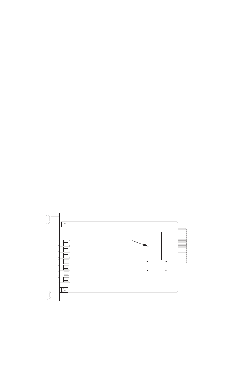
The DCE/DTE strap is located near the rear of the Model 2020RC
front card’s PC board (see Figure 1, below). The arrows on the strap,
and on the PC board itself, indicate the configuration of the Model
2020RC. For example, if the “DCE” arrows on the strap are pointing
toward the front of the card (with the “DTE” arrows pointing toward the
rear), then the Model 2020RC is wired so that the RS-232 port is a DCE
and the V.35 port is a DTE. You can confirm this by reading the “RS232” and “V.35” arrows on the PC board.
To reverse the DCE/DTE orientation of the Model 2020RC, remove the
strap and rotate it 180
0
. Confirm the orientation by checking the arrows
on the strap and on the PC board.
Figure 1. Model 2020RC front card, showing location of the DCE/DTE strap.
4
DCE/DTE strap
DTE
➨
➨
➨
➨
RS-232
V.35
Page 6

3.2 REAR CARD CONFIGURATION
The rear interface card for the Model 2020RC is equipped with two
female UD-26 connectors: one for each port. This card has one
configuration jumper (JB4). Figure 2 (below) shows the location of this
jumper on the PC board.
As Figure 3 (below) shows, jumper JB4 has two possible
positions: strap covering posts 1 & 2, or strap covering posts 2 & 3.
The orientation of the jumper with respect to pin positions is shown in
Figure 4
(above).
SGND & FRGND (JB4)
In the connected position, this jumper links UD-26 pin 7 (Signal
Ground) and frame ground. In the open position, pin 1 is “lifted” from
frame ground.
JB4
Position 1&2 = SGND (UD-26 pin 7)
and FRGND Connected
5
Figure 2. Rear card jumper location
JB4
(peg 1 toward
bottom of card,
peg 3 toward top
of card)
Figure 3. Possible function card strap positions
Page 7

Position 2&3 = SGND (UD-26 pin 7)
and FRGND Not Connected
6
Figure 4. Model 1000R16P Rack Chassis with Power Supply
WARNING! There are no user-serviceable parts in the
power supply section of the Model 2020RC. Voltage
setting changes and fuse replacement should only be
performed by qualified service personnel. Contact Patton
Electronics Technical support at (301)975-1007 for more
information.
Page 8

4.0 INSTALLATION
This section describes the functions of the Model 1000R16P rack
chassis, tells how to install front and rear Model 2020RC cards into the
chassis and provides diagrams for wiring up the interface connections
correctly.
4.1 THE MODEL 1000R16P RACK CHASSIS
The 1000R16P Rack Chassis (shown in Figure 4, below) has
sixteen short range modem card slots, plus its own power supply.
Measuring only 3.5" high, the 100016RP is designed to occupy only 2U
in a 19" rack. Sturdy front handles allow the 1000R16P to be extracted
and transported conveniently.
4.1.1 THE RACK POWER SUPPLY
The power supply included in the Model 1000R16P rack uses the
same mid-plane architecture as the modem cards. The front card of
the power supply slides in from the front, and the rear card slides in
from the rear. They plug into one another in the middle of the rack.
The front card is then secured by spring loaded thumb screws and the
rear card by conventional metal screws.
(continued)
7
Page 9

Switching the Power Supply On and Off
The power switch is located on the front panel. When plugged in
and switched on, a red front panel LED will glow. Since the Model
1000R16P is a "hot swappable" rack,
it is not necessary for any cards
to be installed before switching on the power supply
. The power supply
may be switched off at any time without harming the installed cards.
NOTE: Please refer to the Model 1000RP Series User Manual
AC
and DC Rack Mount Power Supplie
s for fuse and power card
replacement information.
4.2 INSTALLING THE MODEL 2020RC INTO THE CHASSIS
The Model 2020RC is comprised of a front Function card and a
rear Interface card. The two cards connect in the rack chassis via
mating 50 pin card edge connectors. Use the following steps as a
guideline for installing each Model 2020RC into the Model 1000R16P
rack chassis:
1. Slide the rear Interface card into the back of the chassis along the
metal rails.
2. Secure the rear card using the metal screws provided.
3. Slide the Function card into the front of the chassis. It should
meet the rear card when it's almost all the way into the
8
Figure 5. Model 2020RC rear interface card, showing connectors
A1 B1
Notice! Any terminal cable connected to the Model
2020RC must be shielded cable, and the outer shield must
be 360 degree bonded–at both ends–to a metal or
metalized backshell.
Page 10

chassis.
4. Push the front card
gently
into the card-edge receptacle of the rear
card. It should "click" into place.
5. Secure the front card using the spring loaded thumb screws.
NOTE: Since the Model 1000R16P chassis allows "hot swapping"
of cards, it is not necessary to power down the rack when you i
install or remove a Model 2020RC.
9
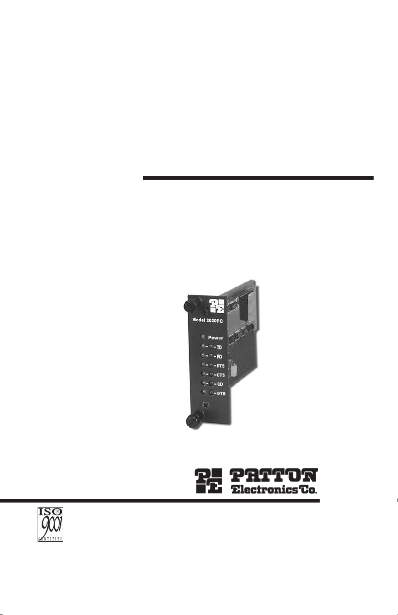
Figure 6. The Model 2020RC front panel, showing LED positions
Model 2020RC
Power
TD
RD
RTS
CTS
CD
DTR
Page 11

4.3 DCE/DTE CONNECTION
The Model 2020RC rear card has two UD-26 connectors, labeled
“A1” and “B1” (see figure 5, below). Port A1 connects to the RS-232
device. Port B1 connects to the V.35 device. As discussed in Section
3.1, the ports may be configured as DCE-to-DTE or DTE-to-DCE.
To connect computing devices to ports A1 and B1 on the Model
2020RC, follow these instructions:
1. Configure the Model 2020RC for your specific application
according to the instructions in Section 3.0 of this manual.
2. Connect computing devices to the Model 2020RC using multipair
adapter cables (see Appendix B for a list of custom adapter
cables available from Patton Electronics). Either the RS-232 or the
V.35 device may supply the clock. The wiring of your adapter
cables should support your system’s timing requirements.
10
Page 12

5.0 OPERATION
Once you have configured each Model 2020RC and connected the
cables, you are ready to operate the units. This section describes the
LED status monitors, clocking requirements and the power-up
procedure.
5.1 LED STATUS MONITORS
The Model 2020RC features thirteen front panel LEDs that indicate
the condition of the modem and communication link. Figure 6 (below)
shows the positions of the LEDs, and the bullets describe their
functions.
• Power - will glow green when power is applied to the Model
2020RC front card.
• TD (Transmit Data) - indicates status of transmit data from the
DTE. Red indicates a mark or idle state. Green indicates a space
or active state.
• RD (Receive Data) - indicates status of receive data from the
DCE. Red indicates a mark or idle state. Green indicates a space
or active state.
• RTS (Request to Send) - indicates status of Request to Send
from the DTE. Red indicates a mark or idle state. Green indicates
a space or active state.
• CTS (Clear to Send) - indicates status of Clear to Send from the
DCE. Red indicates a mark or idle state. Green indicates a space
or active state.
(continued)
• CD (Carrier Detect) - indicates status of Carrier Detect from the
11
Page 13

DCE. Red indicates a mark or idle state. Green indicates a space
or active state.
• DTR (Data Terminal Ready) - indicates status of Data Terminal
Ready from the DTE. Red indicates a mark or idle state. Green
indicates a space or active state.
5.2 CLOCKING
The Model 2020RC supports all clocking methods, whether clock is
supplied by the DCE or DTE, and whether it is supplied by the V.35 or
RS-232 device. No special configuration of the Model 2020RC is
required (or possible) with respect to clocking.
5.2 POWER-UP
There is no power switch on the Model 2020RC: Power is
automatically applied to the 2020RC when its card-edge connector
touches the chassis' mid-plane socket, or when the chassis' power is
turned on.
Note: The 2020RC is a "hot swappable" card—it will not be
damaged by plugging it in or removing it while the rack is powered up.
12
Page 14

APPENDIX A
MODEL 2020RC SPECIFICATIONS
Function: Bidirectional RS-232 to V.35 conversion
Transmission Format: Synchronous, transparent to protocol, full or
half duplex; passes all appropriate
control signals
External Interface: Dual UD-26 female high density connectors
Data Rates: Up to 384 kbps
Configuration: DTE/DCE, strap switchable
Clocking: Supplied by the connected devices
13
13- Not Used
12- Not Used
11- Not Used
10- Not Used
9- Not Used
8- (CD) Carrier Detect
7- (SG) Signal Ground
6- (DSR) Data Set Ready
5- (CTS) Clear to Send
4- (RTS) Request to Send
3- (RD) Receive Data
2- (TD) Transmit Data
1- (FG) Frame Ground
MODEL 2020RC RS-232 INTERFACE
Not Used -26
Not Used -25
External Clock (XC) -24
Not Used -23
Not Used -22
Not Used -21
Data Term Ready (DTR) -20
Not Used -19
Not Used -18
Receive Clock (RC) -17
Not Used -16
Transmit Clock (TC) -15
Not Used -14
13- Not Used
12- (TC-b) Trans Clock (b)
11- (XC-b) Ext Clock (b)
10- Not Used
9- (RC-b) Receive Clock (b)
8- (CD) Carrier Detect
7- (SG) Signal Ground
6- (DSR) Data Set Ready
5- (CTS) Clear to Send
4- (RTS) Request to Send
3- (RD-a) Receive Data (a)
2- (TD-a) Transmit Data (a)
1- (FG) Frame Ground
MODEL 2020RC V.35 INTERFACE
Not Used -26
Not Used -25
External Clock (a) (XC-a) -24
Not Used -23
Not Used -22
Not Used -21
Data Term Ready (DTR) -20
Not Used -19
Not Used -18
Receive Clock (a) (RC-a) -17
Receive Data (b) (RD-b) -16
Trans Clock (a) (TC-a) -15
Transmit Data (b) (TD-b) -14
Page 15
Electrical Interface: RS-232: RS-232/V.24 compatible; V.35 data
and clock receivers: V.35
compliant; V.35 data and
clock drivers: 0.55V differential signal;
V.35 control signals: RS-232/V.24 compatible
14
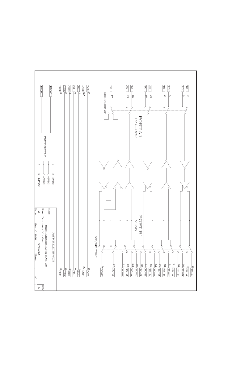
APPENDIX D
PATTON MODEL 2020RC BLOCK DIAGRAM
Copyright ©
Patton Electronics Company
All Rights Reserved
Page 16

An ISO-9001
Certified Company
Dear Valued Customer,
Thank you for purchasing Patton Electronics products! We do
appreciate your business. I trust that you find this user manual helpful.
We manufacture one of the widest selections of data communications
products in the world including CSU/DSU's, network termination units,
powered and self-powered short range modems, fiber optic modems, interface
converters, baluns, electronic data switches, data-line surge protectors,
multiplexers, transceivers, hubs, print servers and much more. We produce
these products at our Gaithersburg, MD, USA, facility, and can custom
manufacture products for your unique needs.
We would like to hear from you. Please contact us in any of the
following ways to tell us how you like this product and how we can meet your
product needs today and in the future.
Web: http://www.patton.com
Sales E-mail: sales@patton.com
Support E-mail: support@patton.com
Phone - Sales (301) 975-1000
Phone - Support (301) 975-1007
Fax: (301) 869-9293
Mail: Patton Electronics Company
7622 Rickenbacker Drive
Gaithersburg, MD 20879 USA
We are committed to a quality product at a quality price. Patton
Electronics is ISO 9001 certified. We meet and exceed the highest standards
in the industry (CE, UL, etc.).
It is our business to serve you. If you are not satisfied with any
aspect of this product or the service provided from Patton Electronics or its
distributors, please let us know.
Thank you.
Burton A.Patton
Vice President
P.S. Please tell us where you purchased this product:
_________________________________________________________
_________________________________________________________
_________________________________________________________
_________________________________________________________
_________________________________________________________
_________________________________________________________
 Loading...