

Page 1
USER
MANUAL
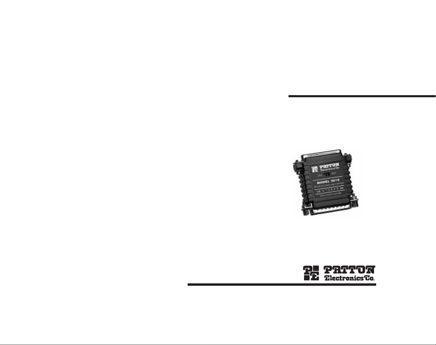
MODEL 2018
RS-232 to
Current Loop Converter
SALES OFFICE
(301) 975-1000
TECHNICAL SUPPORT
(301) 975-1007
http:www.patton.com
Part# 07M2018-B
Doc# 07304UB
Revised 3/31/94
Page 2

1.0 WARRANTY INFORMATION
Patton Electronics warrants all Model 2018 components to be
free from defects, and will—at our option—repair or replace the product should it fail within one year from the first date of shipment.
This warranty is limited to defects in workmanship or materials,
and does not cover customer damage, abuse or unauthorized modification. If this product fails or does not perform as warranted, your sole
recourse shall be repair or replacement as described above. Under no
condition shall Patton Electronics be liable for any damages incurred
by the use of this product. These damages include, but are not limited
to, the following: lost profits, lost savings and incidental or consequential damages arising from the use of or inability to use this product.
Patton Electronics specifically disclaims all other warranties,
expressed or implied, and the installation or use of this product shall
be deemed an acceptance of these terms by the user.
1.1 RADIO AND TV INTERFERENCE
The Model 2018 generates and uses radio frequency energy, and
if not installed and used properly—that is, in strict accordance with the
manufacturer's instructions—may cause interference to radio and television reception. The Model 2018 has been tested and found to comply with the limits for a Class A computing device in accordance with
the specifications in Subpart J of Part 15 of FCC rules, which are
designed to provide reasonable protection from such interference in a
commercial installation. However, there is no guarantee that interference will not occur in a particular installation. If the Model 2018 does
cause interference to radio or television reception, which can be determined by disconnecting the RS-232 interface, the user is encouraged
to try to correct the interference by one or more of the following measures: moving the computing equipment away from the receiver, re-orienting the receiving antenna and/or plugging the receiving equipment
into a different AC outlet (such that the computing equipment and
receiver are on different branches).
1.2 SERVICE
All warranty and non-warranty repairs must be returned freight
prepaid and insured to Patton Electronics. All returns must have a
Return Materials Authorization number on the outside of the shipping
container. This number may be obtained from Patton Electronics
Technical Service at (301) 975-1007.
Packages received without an
RMA number will not be accepted.
Patton Electronics' technical staff is also available to answer any
questions that might arise concerning the installation or use of your
Model 2018. Technical Service hours: 8AM to 5PM EST, Monday
through Friday.
1
2.0 GENERAL INFORMATION
Thank you for your purchase of this Patton Electronics product.
This product has been thoroughly inspected and tested and is warranted for One Year parts and labor.
If any questions or problems arise during installation or use of this
product, please do not hesitate to contact Patton Electronics Technical
Support at (301) 975-1007.
2.1 FEATURES
• Full duplex, asynchronous transmission over 4 wires
• Operates actively or passively
• Data rates from 50 to 115,200 bps
• Range to 5 miles on 24 AWG twisted pair
• No AC power required
• Optically isolated on line side
• DB-25 connectors on both ends
• External DCE/DTE switch
• Made in the USA
2.2 DESCRIPTION
The Model 2018 RS-232 to current loop converter lets an asyn-
chronous RS-232 device communicate with a 20mA or 60mA current
loop device. The Model 2018 requires no AC power or batteries to
operate and supports data rates to 115.2 Kbps. When connected to an
active current loop interface, no additional power is needed. When
connected to a passive current loop interface, DC line power may be
applied to the Model 2018 via pins 9 and 21 of the DB-25 current loop
interface.
Operating full duplex, the Model 2018 supports communication
distances up to 5 miles over two unconditioned twisted pair. To guard
against data loss due to ground loops, the Model 2018 is equipped
with 2500V RMS optical isolators on the line side.
The Patton Model 2018 connects directly to either the RS-232
interface or the 20mA or 60mA current loop interface using a male or
female DB-25 connector. An external DCE/DTE switch on the Model
2018 eliminates the need for a crossover cable on the RS-232 interface. The Model 2018 is manufactured in the USA.
2
Page 3

3.0 CONFIGURATION
The Model 2018 is designed to be easy to use. There are no internal jumpers or DIP switches to set, so there is no need to open the
case to configure the unit. The only configuration necessary for operation is proper setting of the external DCE/DTE switch.
3.1 SETTING THE DCE/DTE SWITCH
For your convenience, the Model 2018 has an externally accessible DCE/DTE switch (see Figures 1 and 2). If the RS-232 device connected to the Model 2018 is a modem or multiplexer (or is wired like
one), set the switch to “DTE”. This setting causes the Model 2018 to
behave like Data Terminal Equipment, transmitting data on RS-232 pin
2 and receiving data on pin 3.
If the RS-232 device connected to the Model 2018 is a PC, terminal or host computer (or is wired like one), set the switch to “DCE”.
This setting causes the Model 2018 to behave like Data
Communications Equipment, transmitting data on RS-232 pin 3 and
receiving data on pin 2. Remember: The switch setting is always from
the point of view of the Model 2018, not the connected equipment.
3.1.1 DCE/DTE SWITCH POSITIONS
The unique characteristics of this product made it necessary to
reverse the DCE/DTE switch positions on half of the models. Since the
switch positions are clearly marked on the label of your Model 2018,
you should have no trouble seeing which way to move the switch. But
just to double-check, refer to Figures 1 and 2 and make sure the markings on your unit correspond to those below:
Figure 1. Switch positions for 2018MF and 2018FF
Figure 2. Switch positions for 2018FM and 2018MM
43
4.0 INSTALLATION
The versatile Model 2018 can be installed in at least three different
applications: RS-232 to
active
current loop, RS-232 to
passive
current
loop and RS-232 to RS-232 (distances to 5 miles over two twisted
pair).
4.1 RS-232 TO ACTIVE CURRENT LOOP
The simplest installation of the Model 2018 is into environments
where an RS-232 device is communicating with an
active
current loop
device. In this case, both the RS-232 and current loop interfaces are
automatically supplying power to the data circuit. As Figure 3 illustrates, only 4 wires are needed to connect the current loop side of the
Model 2018 to the current loop device interface. For best results,
these 4 wires should be in twisted pairs.
To install the Model 2018 in an active current loop environment,
you will need a DB-25 cable with at least 4 conductors. These conductors should be wired to the appropriate DB-25 pins as shown in
Figure 3. Since this end of the cable connects to the Model 2018, its
gender should be
opposite
to that of the Model 2018's connector.
When you connect this cable to your current loop device, be sure the
signal paths correspond to those shown.
The RS-232 side of the Model 2018 is designed to plug directly
into the serial port of your RS-232 device. You may use a straight
through RS-232 cable for connection as well. Be sure to set the Model
2018's DCE/DTE switch according to the instructions in Section 3.0 of
this manual.
Figure 3. Connection to an active current loop interface
Model 2018
RS-232 Side
Current Loop
14 (T+)
19 (T-)
25 (R+)
23 (R-)
(R+)
(R-)
(T+)
(T-)
Active Current
Loop Device
DTE
DCE
DCE
DTE
DCE DTE
DCE DTE
Page 4

4.3 RS-232 TO RS-232 DISTANCE EXTENSION
You may use the Model 2018 as a distance extender for RS-232
to RS-232 applications. In this case, you will need
two
Model 2018
converters, plus an external DC power source* on one end of the communication link. Figure 5 shows the appropriate pin/voltage for applying external DC power to the Model 2018 link.
To use two Model 2018s as RS-232 distance extenders, you will
need a DB-25 cable with at least two twisted pairs (19 - 26 AWG).
Your cable should be custom-wired as shown in Figure 5. Be sure the
genders of the cable's DB-25 connectors are
opposite
to those of the
respective Model 2018s. The maximum cable length depends on various factors, including overall cable capacitance, data rate, noise and
operating environment. Call Patton Technical Support at (301) 9751007 if you have any questions.
The RS-232 side of the Model 2018 is designed to plug directly
into the serial port of your RS-232 device. You may use a straight
through RS-232 cable for connection as well. Be sure to set the Model
2018's DCE/DTE switch according to the instructions in Section 3.0 of
this manual.
Figure 5. RS-232 distance extension
*Note: A 12V DC power adapter is available from Patton Electronics
4.2 RS-232 TO PASSIVE CURRENT LOOP
You may install the Model 2018 into environments where an
RS-232 device is communicating with a
passive
current loop device.
In this case, you will need to supply external DC power* to the Model
2018 on the current loop interface side. Figure 4 shows the appropriate pins/voltages for applying external DC power to the Model 2018.
To install the Model 2018 in a passive current loop environment,
you will need a DB-25 cable with at least 3 conductors plus shield.
Wire the cable as shown in Figure 4, paying attention to jumpers and
signal paths. Since this end of the cable connects to the Model 2018,
its gender should be
opposite
to that of the Model 2018's connector.
When you connect this cable to your current loop device, be sure the
signal paths correspond to those shown.
The RS-232 side of the Model 2018 is designed to plug directly
into the serial port of your RS-232 device. You may use a straight
through RS-232 cable for connection as well. Be sure to set the Model
2018's DCE/DTE switch according to the instructions in Section 3.0 of
this manual.
Figure 4. Connection to a passive current loop interface
*Note: A 12V DC power adapter is available from Patton Electronics
5 6
Model 2018
RS-232 Side
Current Loop
14 (T+)
19 (T-)
6
9
21
22
25 (R+)
23 (R-)
(R+)
(R-)
(T+)
(T-)
Passive
Current Loop
Device
12V DC
12V DC
Model 2018
RS-232 Side
Current Loop
14 (T+)
19 (T-)
6
21
9
22
23 (R-)
25 (R+)
(R-) 23
(R+) 25
(T+) 14
(T-) 19
Model 2018
RS-232 Side
Current Loop
12VDC
Power
Supply
Page 5

APPENDIX A
PATTON MODEL SPECIFICATIONS
Transmission Line: 19 to 26 AWG twisted pair
Range: Up to 5 miles on 24 AWG twisted pair
Interfaces: Asynchronous, EIA RS-232, CCITT V.24 full
duplex; 20mA or 60mA current
loop
Data Rates: 50 - 115,200 bps
Isolation: 2500V RMS via opto-isolators on line side
Connectors: DB-25 male or female on both RS-232 and
current loop sides
Power Supply: No external power; uses power from NIC
data and control signals
Temperature Range: 0-60°C (32-140°F)
Altitude: 0-15,000 feet
Humidity: 5 to 95% noncondensing
Dimensions: 2.21”l x 0.8”h x 2.10”w
Weight: 1.7 oz
APPENDIX B
BLOCK DIAGRAM
7 8
Page 6

APPENDIX C
RS-232 PIN CONNECTIONS
APPENDIX D
CURRENT LOOP PIN CONNECTIONS
1- (FG) Frame Ground
2- (TD) Transmit Data To Mdl 2018
3- (RD) Receive Data From Mdl 2018
4- (RTS) Request to Send To Mdl 2018
5- (CTS) Clear to Send From Mdl 2018
6- (DSR) Data Set Ready From Mdl 2018
7- (SG) Signal Ground
8- (DCD) Data Carrier Detect From Mdl 2018
To Mdl 2018 Data Term. Ready (DTR) - 20
DIRECTION "DCE" SETTING DIRECTION
1- (FG) Frame Ground
2- (TD) Transmit Data From Mdl 2018
3- (RD) Receive Data To Mdl 2018
4- (RTS) Request to Send From Mdl 2018
5- (CTS) Clear to Send To Mdl 2018
6- (DSR) Data Set Ready To Mdl 2018
7- (SG) Signal Ground
8- (DCD) Data Carrier Detect To Mdl 2018
From Mdl 2018 Data Term. Ready (DTR) - 20
DIRECTION "DTE" SETTING DIRECTION
9 10
6
9
(TX+) 14
(TX-) 19
21
22
(RX-) 23
(RX+) 25
 Loading...