

Page 1
USER
MANUAL
MODEL 2017RC
Miniature RS-232 to 20mA
Current Loop Converter:
Dual Port Rack Mount Card
SALES OFFICE
(301) 975-1000
TECHNICAL SUPPORT
(301) 975-1007
http://www.patton.com
An ISO-9001
Certified Company
Part# 07M2017RC-B
Doc# 073062U, Rev. C
Revised 1/22/08
CERTIFIED
Page 2

1.0 WARRANTY INFORMATION
Patton Electronics warrants all Model 2017RC components to be
free from defects, and will—at our option—repair or replace the product
should it fail within one year from the first date of shipment.
This warranty is limited to defects in workmanship or materials,
and does not cover customer damage, abuse or unauthorized
modification. If this product fails or does not perform as warranted,
your sole recourse shall be repair or replacement as described above.
Under no condition shall Patton Electronics be liable for any damages
incurred by the use of this product. These damages include, but are
not limited to, the following: lost profits, lost savings and incidental or
consequential damages arising from the use of or inability to use this
product. Patton Electronics specifically disclaims all other warranties,
expressed or implied, and the installation or use of this product shall be
deemed an acceptance of these terms by the user.
1.1 RADIO AND TV INTERFERENCE
The Model 2017RC generates and uses radio frequency energy,
and if not installed and used properly—that is, in strict accordance with
the manufacturer's instructions—may cause interference to radio and
television reception. The Model 2017RC has been tested and found to
comply with the limits for a Class A computing device in accordance
with the specifications in Subpart J of Part 15 of FCC rules, which are
designed to provide reasonable protection from such interference in a
commercial installation. However, there is no guarantee that
interference will not occur in a particular installation.
If the Model 2017RC does cause interference to radio or television
reception, which can be determined by turning the power off or
disconnecting the unit, the user is encouraged to try to correct the
interference by one of the following measures: moving the computing
equipment away from the receiver, re-orienting the receiving antenna,
and/or plugging the receiving equipment into a different AC outlet (such
that the computing equipment and receiver are on different branches).
If the user detects intermittent or continuous product malfunction
due to nearby high power transmitting radio frequency equipment, the
user is advised to use data cables with an external outer shield bonded
to a metal or metalized connector, and to configure the rear card as
shown in Section 3.2 of this manual.
1
Page 3

1.2 CE NOTICE
The CE symbol on your Patton Electronics equipment indicates
that it is in compliance with the Electromagnetic Compatibility (EMC)
directive and the Low Voltage Directive (LVD) of the Union European
(EU). A Certificate of Compliance is available by contacting Technical
Support.
1.3 SERVICE
All warranty and non-warranty repairs must be returned freight
prepaid and insured to Patton Electronics. All returns must have a
Return Materials Authorization number on the outside of the shipping
container. This number may be obtained from Patton Electronics
Technical Service at (301) 975-1007; http://www.patton.com; or
support@patton.com.
Packages received without an RMA number
will not be accepted.
Patton Electronics' technical staff is also available to answer any
questions that might arise concerning the installation or use of your
Model 2017RC. Technical Service hours: 8AM to 5PM EST, Monday
through Friday.
2
Page 4

2.0 GENERAL INFORMATION
Thank you for your purchase of this Patton Electronics product.
This product has been thoroughly inspected and tested and is
warranted for one year parts and labor. If any questions or problems
arise during installation or use of this product, please do not hesitate to
contact Patton Electronics Technical Support at (301) 975-1007.
2.1 FEATURES
• Bi-directional RS-232 to 20mA current loop conversion
• 2 Independent interface converters per card
• Full duplex, asynchronous transmission over two twisted pairs
• Switch selectable active/passive transmitter
• Optical Isolation and Surge Suppression
• Front Panel LED indicators for TD, RD and power
• Selectable receiver impedance
• Made in the USA
2.2 DESCRIPTION
The Patton Model 2017RC Interface Converter Rack Card is a
dual rack card that lets two asynchronous RS-232 devices
communicate bi-directionally with two asynchronous 20mA current loop
devices. Operating full duplex on both ports, the Model 2017RC
supports data rates to 115.2 kbps.
Internal active/passive switches allow the user to configure the
Model 2017RC with an active or passive transmitter. This unique
feature allows configuration to fit a wide variety of current loop
applications. The Model 2017RC uses Patton’s mid-plane architecture
and is equipped with dual RJ-45 connectors on the rear interface card
(adapter cables are available from Patton Electronics).
The Model 2017RC is designed to mount in Patton’s 2U high 19”
rack chassis and 2/4/8 slot Cluster Boxes. The combination of rack
mount, Cluster Box and interface powered units provides a completely
integrated “networking” solution. The Model 2017RC is made in the
USA.
3
Page 5
3.0 CONFIGURATION
This section describes the location and orientation of the Model
2017RC's configuration straps, and details all possible settings. This
section also identifies factory default configuration settings.
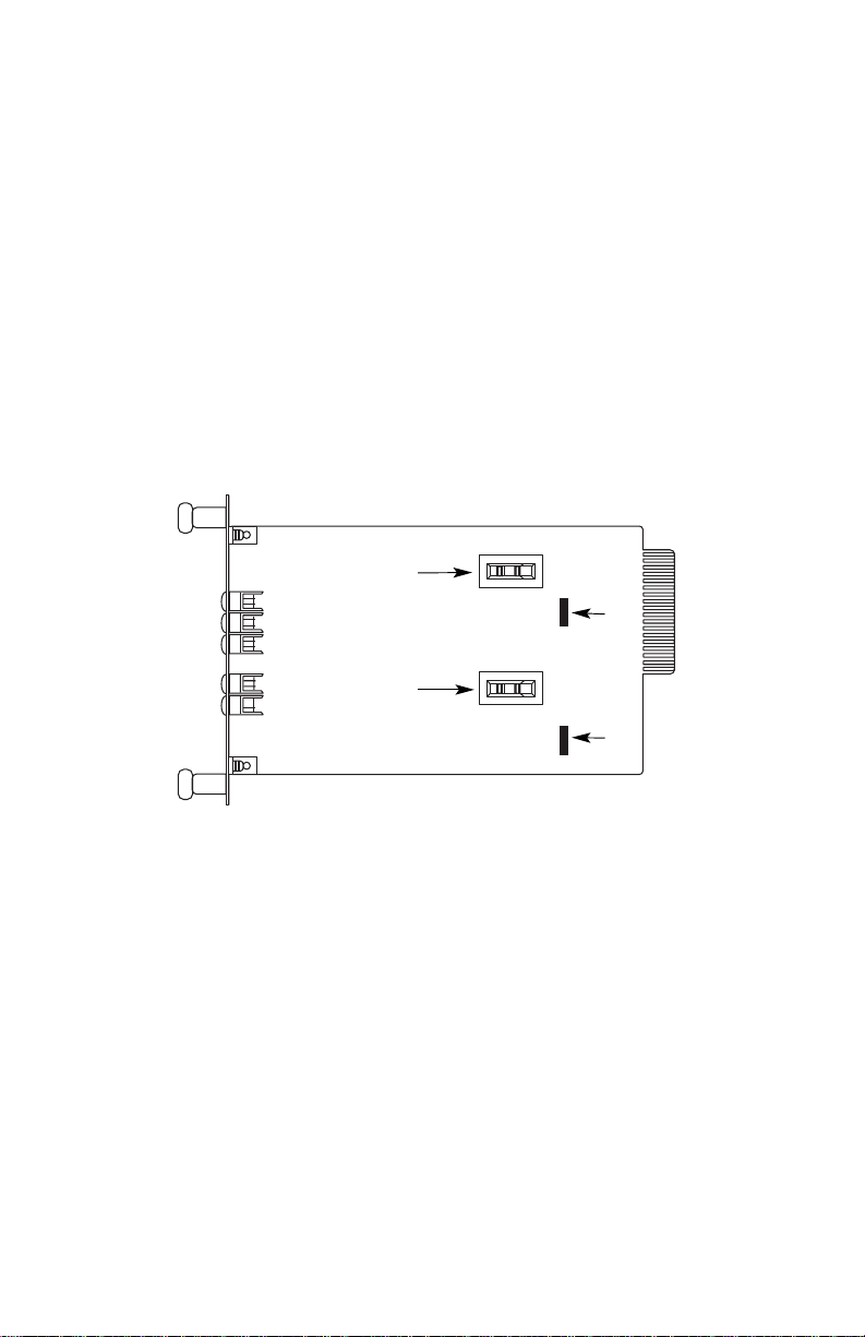
3.1 FRONT CARD CONFIGURATION
The Model 2017RC uses one switch and one jumper per port that
allow configuration to a wide range of asynchronous applications.
These switches and jumpers are accessible when the card is slid out of
the rack chassis. Figure 1 shows the switches and jumpers on the
position of the Model 2017RC PC board.
3.1.1 Active/Passive Configuration
In any closed current loop, the transmitter
or
the receiver acts as
the active current source, while the other of the two must be passive.
To configure the Model 2017RC active/passive modes, you must first
determine whether the transmitter should be active or passive.
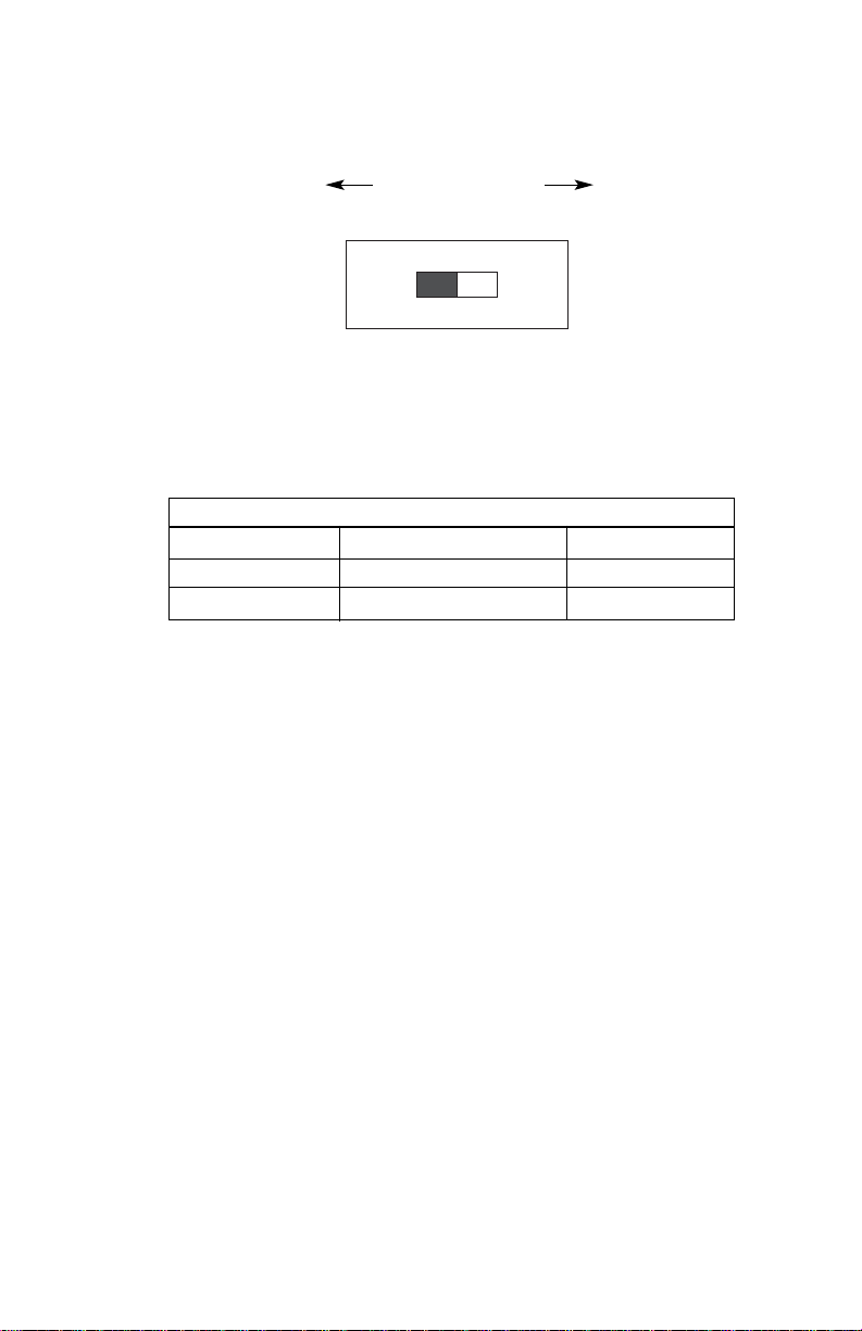
The active/passive switches are used to control the mode of the
20mA transmitters. Each converter on the dual port card has one
switch. As Figure 2 shows, the switch controls the mode of the
transmitter.
The Model 2017RC receivers are always passive.
WARNING: Never connect two active devices together. Your
configurations must be "active to passive" or "passive to active".
Figure 1. Model 2017RC front card, showing location of the Switches and Jumpers
4
Active/PassiveSwitch
- Port A
Active/PassiveSwitch
- Port B
JB1
JB2
1
2
3
1
2
3
N
L
N
L
Page 6
The following table shows the factory default settings of switches
S1 and S3. Following the table are descriptions of each switch.
Switches S1 and S3: Transmitter Active/Passive Select
Slide switches S1 (TXA) and S3 (TXB) are used to set the port A
and port B transmitter modes of operation, respectively. When the
active mode of operation is selected, the Model 2017RC transmitter will
supply the 20mA loop current to the connected passive receiver. When
the passive mode of operation is selected, the Model 2017RC
transmitter must be connected to an active receiver.
5
ACTIVE PASSIVE
TX
SWITCH SUMMARY TABLE
Position Function Factory Default
S1 Transmitter (A) Mode Select Active
S3 Transmitter (B) Mode Select Active
Figure 2. Orientation of transmitter active/passive switch
PORT A
DCE DTE
Page 7

3.1.2 Setting the Receiver Impedance Straps
JB1 and JB2 are used to set the input impedance of the port A and
port B receivers, respectively. This allows the user to choose the
optimum impedance setting for the particular application. There are
two possible positions for JB1 and JB2: strap covering posts 1 & 2, or
strap covering posts 2 & 3. Figure 3 shows the orientation of the strap
with respect to its post positions.
The following table provides a summary of strap functions rear
interface card.
Straps JB1 and JB2: Receiver Impedance
In the normal setting, JB1 and JB2 are positioned on posts 1 and
2. The “Normal” setting is best suited for applications in which two
Model 2017RCs are used together. The low impedance setting may
improve performance with other current loop devices.
JB1
Position 1&2 = Normal
(default)
Position 2&3 = Low Receiver Impedance
JB2
Position 1&2 = Normal
(default)
Position 2&3 = Low Receiver Impedance
NOTE: peg 1 is oriented toward top of card, peg 3 is oriented toward bottom of card
6
Strap Position 1&2 Position 2&3
JB1 Normal
†
Low
JB2 Normal
†
Low
IMPEDANCE STRAP SUMMARY TABLE
NOTE: †indicates factory default
Figure 3. Orientation of interface card straps
123 123 123
Page 8

3.2 REAR CARD CONFIGURATION
The Model 2017RC has two interface card options: the 1Q11 (which
comes equipped with two RJ-11 ports and two RJ-45 ports) and the
1Q45 (which comes equipped with four RJ-45 ports). Figure 4
illustrates these two different rear interface options.
Prior to installation, you should examine the rear card you have
selected and ensure that it is suitable for your application. Each rear
card is configured by setting straps on the PC board. Section 3.2.1
describes the strap locations and settings for each card.
3.2.1 REAR CARD STRAP SETTINGS
Figure 5 shows the strap locations for the 1Q11 and the 1Q45 rear
cards. These straps determine various grounding characteristics for
the RS-232 and twisted pair lines.
7
Figure 4. Model 1000RC rear interface card options
RJ-11/6
RJ-45/10
1Q45
1Q11
RJ-11/6
RJ-45/10
RJ-45/10
RJ-45/10
RJ-45/10
RJ-45/10
Figure 5. Strap locations for both rear cards
1
2
3
1
2
3
1
2
3
1
2
3
123
(Unit A)
JB2
JB4
JB6
JB7
JB5
(Unit B)
(Unit A)
(Unit B)
Converter
twisted pair
}
}
Page 9

The table below provides a summary of strap functions for both of
the rear cards. Descriptions of each strap follow the table.
Line A Shield & Line B Shield (JB2 & JB4)
This strap pertains to the line interface. In position 1&2, the strap
links RJ-11 pins 1 and 6 (RJ-45 pins 2 and 7) to frame ground and the
rear panel. These pins can be used as connections for the twisted pair
cable shield. In position 2&3, pins 1 and 6 (or 2 and 7) are
disconnected from frame ground.
JB2
Position 1&2 = Line A Shield Connected to Frame Ground
Position 2&3 = No Shield
JB4
Position 1&2 = Line B Shield Connected to Frame Ground
Position 2&3 = No Shield
SGND & FRGND (JB5)
In position 1&2, this strap links signal ground and frame ground
through a 100 Ohm, 1/2 W resistor. In position 2&3, pin 1 is “not
connected to frame ground.
JB5
Position 1&2 = SGND and FRGND Connected
Position 2&3 = SGND and FRGND Not Connected
8
Strap Position 1&2 Position 2&3
JB2 Line A Shield No Shield
†
JB4 Line B Shield No Shield
†
JB5 SGND & FRGND* Open (Not Connected)
†
JB6 Unit A DSR
†
N/A
JB7 Unit B DSR
†
N/A
INTERFACE CARD STRAP SUMMARY TABLE #1
NOTE†indicates factory default
*via 100 ohm resistor
Page 10

DTE as DSR or RI (JB6 & JB7)
Because the Model 2017RC uses DSR (but not RI), only position
1&2 is valid when this rear card is used. Position 1&2 causes the
terminal (DTE) to see DSR when the Model 2017RC is powered up
properly. Position 2&3 is for Ring Indicate, which is not used on the
Model 2017RC. Furthermore, use of position 2&3 will cause DSR to
float, which will lead to improper operation of the Model 2017RC.
JB6 &
JB7
Position 1&2 = DSR
Position 2&3 = Not a V
alid Setting for Model 2017RC
9
Page 11

4.0 INSTALLATION
This section describes the functions of the Model 1000R16 rack
chassis, tells how to install front and rear Model 2017RC cards into the
chassis and provides diagrams for wiring up the interface connections
correctly.
4.1 THE MODEL 1000R16 RACK CHASSIS
The Model 1000R16 Rack Chassis (Figure 6) has sixteen short
range modem card slots, plus its own power supply. Measuring only
3.5” high, the Model 1000R16 is designed to occupy only 2U in a 19”
rack. Sturdy front handles allow the Model 1000R16 to be extracted
and transported conveniently.
4.1.1 THE RACK POWER SUPPLY
The power supply included in the Model 1000R16 rack uses the
same mid-plane architecture as the modem cards. The front card of
the power supply slides in from the front, and the rear card slides in
from the rear. They plug into one another in the middle of the rack.
The front card is then secured by thumb screws and the rear card by
conventional metal screws.
10
WARNING! There are no user-serviceable parts in the
power supply section of the Model 2017RC. Fuse
replacement should only be performed by qualified
service personnel. Contact Patton Electronics Technical
support at (301)975-1007 for more information.
Figure 6. Model 1000R16 Rack Chassis with Power Supply
Page 12

Switching the Power Supply On and Off
The power switch is located on the front panel. When plugged in
and switched on, a red front panel LED will glow. Since the Model
1000R16 is a “hot swappable” rack,
it is not necessary for any cards to
be installed before switching on the power supply
. The power supply
may be switched off at any time without harming the installed cards.
NOTE: Please refer to the Model 1000RP Series User Manual
AC
and DC Rack Mount Power Supplie
s for fuse and power card
replacement information.
4.2 INSTALLING THE MODEL 2017RC INTO THE CHASSIS
The Model 2017RC is comprised of a front card and a rear card.
The two cards meet inside the rack chassis and plug into each other by
way of mating 50 pin card edge connectors. Use the following steps as
a guideline for installing each Model 2017RC into the Model 1000R16
rack chassis:
1. Slide the rear card into the back of the chassis along the metal rails.
2. Secure the rear card using the metal screws provided.
3. Slide the front card into the front of the chassis. It should meet the
rear card when it's almost all the way into the chassis.
4. Push the front card
gently
into the card-edge receptacle of the rear
card. It should “click” into place.
5. Secure the front card using the thumb screws.
Note: Since the Model 1000R16 chassis allows “hot swapping” of
cards, it is not necessary to power down the rack when you
install or remove a Model 2017RC.
4.3 RS-232 CONNECTION
The RS-232 ports are always the
lower
ports on the interface card.
The 10-pin RJ-45 is pinned according a modified modular interface
standard. For specific interface pin-outs, please refer to the diagrams
in Appendix D.
The Model 2017RC is wired as a DCE (Data Communications
Equipment). Therefore, it wants to connect to a DTE (Data Termination
Equipment). If your RS-232 output device is a DTE, you may need to
use a special cable. If your RS-232 output device is DCE, you will
require a null modem connection. Call Patton Technical Support at
(301) 975-1007 for specific installation instructions.
Page 13

12
4.4 TWISTED PAIR CONNECTION
The Model 2017RC operates half or full duplex over two twisted
pairs. In
all
applications, the twisted pair wire must be 26 AWG or
thicker, unconditioned, dry, metallic wire. Both shielded and unshielded
wire yield favorable results. Note: The Model 2017RC can only
communicate in a closed data circuit with another Model 2017RC or a
compatible 20mA device. Dial-up analog circuits, like those in a
standard Hayes-type modem, are
not acceptable.
For further
information, see Appendix B.
4.4.1 POINT-TO-POINT TWISTED PAIR CONNECTION
The 6-position RJ-11 and 8-position RJ-45 jack options for the
Model 2017RC (always the
upper
jack on the rear interface card) are
prewired for a standard TELCO wiring environment. Pin descriptions of
the RJ-11 and RJ-45 modular jacks.
RJ-1
1 SIGNAL RJ-45 SIGNAL
1 ...................GND
†
1 ...................N/C
2 ...................RCV- 2 ...................GND
3 ...................XMT+ 3 ...................RCV-
4 ...................XMT- 4 ...................XMT+
5 ...................RCV+ 5 ...................XMT-
6 ...................GND 6 ...................RCV+
7 ...................GND
8 ...................N/C
Page 14

4.4.2 POINT-TO-POINT TWISTED PAIR CONNECTION
The 6-position RJ-11 and 8-position RJ-45 jack options for the
Model 2017RC–always the
upper
jack on the rear interface card–are
prewired for a standard TELCO wiring environment (See Appendix D
for pin number orientations). Connection of a 4-wire twisted pair circuit
between two or more Model 2017RCs requires a
crossover cable
as
shown in the following charts.
RJ-1
1 Cable
SIGNAL PIN# PIN# SIGNAL
GND
†
1-----------------------6 GND
†
RCV- 2-----------------------4 XMTXMT+ 3 -----------------------5 RCV+
XMT- 4-----------------------2 RCVRCV+ 5 -----------------------3 XMT+
GND
†
6-----------------------1 GND
†
†
Connection to ground is optional
RJ-45 Cable
SIGNAL PIN# PIN# SIGNAL
GND
†
2-----------------------7 GND
†
RCV- 3-----------------------5 XMTXMT+ 4 -----------------------6 RCV+
XMT- 5-----------------------3 RCVRCV+ 6 -----------------------4 XMT+
GND
†
7-----------------------2 GND
†
†
Connection to ground is optional
13
Page 15

5.0 OPERATION
Once you have configured each Model 2017RC and connected the
cables, you are ready to operate the units. This section describes the
LED status monitors, and the power-up procedure.
5.1 LED STATUS MONITORS
The Model 2017RC features nine front panel LEDs that indicate
data activity and power status. Figure 7 (below) shows the positions of
the LEDs. Following Figure 7 are functional descriptions of each LED.
Power glows green when power is applied to the Model
2017RC front card.
TD (Transmit Data) - indicates status of transmit data
from the DTE. Red indicates a mark or idle state.
Green indicates a space or active state.
RD (Receive Data) - indicates status of receive data from
the DCE. Red indicates a mark or idle state. Green
indicates a space or active state.
5.2 POWER-UP
There is no power switch on the Model 2017RC: Power is
automatically applied to the 2017RC when its card-edge connector
touches the chassis' mid-plane socket, or when the chassis' power is
turned on.
Note: The 2017RC is a "hot swappable" card—it will not be
damaged by plugging it in or removing it while the rack is powered up.
14
Figure 7. The Model 2017RC front panel, showing LED positions
Model 2017RC
Power
TD
Unit
A
RD
TD
Unit
B
RD
Page 16

APPENDIX A
MODEL 2017RC SPECIFICATIONS
Data Rates: 0 to 115.2 kbps
Transmission Format: Asynchronous, full duplex
Transmission Line: 19 to 26 AWG unconditioned, 2 twisted
pairs
RS-232 Interface: 10 pin RJ-45 DCE
Control Signals: RTS looped back to CTS, DTR looped back
to DSR and CD
Current loop
Interface: RJ11 (6 position) or RJ45 (8 position)
Drive Voltage: 12 VDC, nominal
Drive Current: 20mA, nominal
Maximum Loop
Voltage: 25 VDC
Maximum Loop
Current: 60mA
Isolation: Optical (passive modes only)
Surge Protection: 27V, 600W Silicon Avalanche Diodes
LED Indicators: Bi-color red/green indicators for TD and RD;
single green LED indicator for power
Power: 1.4W, max @ 10VAC, supplied by rack
Temperature: 0-40°C (32-104°F)
Humidity: 5 to-95%, noncondensing
Dimensions: 0.95”w x 3.1”h x 5.4”l
15
Page 17

APPENDIX B
PATTON MODEL 2017RC CABLE RECOMMENDATIONS
The following statements apply to the Model 2017RC when used as
a short range modem over private twisted pair:
All Patton Electronics Company Short Range Modems (SRMs) are
tested to the distances published in our Catalogs and Specification
Sheets on twisted-pair cable with the following characteristics:
W
ire Gauge Capacitance Resistance
19 AWG 83nF/mi or 15.72 pF/ft. .0163Ω/ft.
22 AWG 83nF/mi or 15.72 pF/ft. .0326Ω/ft.
24 AWG 83nF/mi or 15.72 pF/ft. .05165Ω/ft.
26 AWG 83nF/mi or 15.72 pF/ft. .08235Ω/ft.
We fully expect that the Short Range Modems will operate on lines
with specifications different from those tested, but to reduce the
potential difficulties in the field, one should ensure that the cable being
used has similar or better characteristics (lower capacitance or lower
resistance).
Wire with capacitance of 20pF/ft. or less is suitable for all our Short
Range Modems however, distances may vary from those published in
our catalog. Resistance will also affect distance but not functionality.
Wire should be 26 AWG or larger (smaller AWG#).
Patton products are designed to withstand normal environmental
noise and conditions; however, other environmental factors too
numerous to discuss in this format may affect proper operation of the
SRM’s.
Selection of the proper SRM for an application is critical to
maintaining Customer Satisfaction and must be taken seriously.
Certain models are better suited for particular applications and
environments than others.
16
Page 18

APPENDIX C
FACTORY REPLACEMENT PARTS
The Patton Model 2017RC rack system features custom front and
rear power supply entry modules and other user-replaceable parts.
Model numbers and descriptions for these parts are listed below:
Patton Model #
Description
1000RPEM..........................120/240V Rear Power Entry Module
1000RPSM-2.......................120/240V Front Power Supply Module
1000RPEM-DC ...................DC Rear Power Entry Module
1000RPSM-48A ..................48V Front Power Supply Module
1000RPEM-V ......................120/240V CE Compliant Rear Power
Entry Module
1000RPSM-V ......................120/240V CE Compliant Front Power
Supply Module
0805US ...............................American Power Cord
0805EUR.............................European Power Cord CEE 7
0805UK ...............................United Kingdom Power Cord
0805AUS.............................Australia/New Zealand Power Cord
0805DEN.............................Denmark Power Cord
0805FR ...............................France/Belgium Power Cord
0805IN.................................India Power Cord
0805IS.................................Israel Power Cord
0805JAP..............................Japan Power Cord
0805SW ..............................Switzerland Power Cord
0516FPB1 ...........................Single Width Blank Front Panel
0516FPB4 ...........................4-Wide Blank Front Panel
0516RPB1...........................Single Width Blank Rear Panel
0516RPB4...........................4-Wide Blank Rear Panel
056S1..................................Set of 16 #4 pan head screws/washers
17
Page 19

APPENDIX D
PATTON MODEL 2017RC
INTERFACE SETTINGS AND ORIENTATION
Copyright © 1997
Patton Electronics Company
All rights reserved
PATTON MODULAR INTERFACE - 10 Wire RJ-45
Contact Number Circuit Description
1 N/A Not Used
2 125 DSR
3 109 Received Line Signal Indicator (CD)
4 108 / 2 DTE Ready (DTR)
5 102 Signal Common
6 104 Received Data
7 103 Transmitted Data
8 106 Clear to Send
9 105 / 133 Request to Send / Ready for Receiving
10 N/A Not Used
Pins 2-9 conform to the EIA/TIA-561 eight position non-synchronous interface standard.
For all modular jacks
(6, 8 or 10 position):
Pin 1 is always toward
the bottom when the
rear card is oriented
correctly in the slot
18
Page 20

An ISO-9001
Certified Company
Dear Valued Customer,
Thank you for purchasing Patton Electronics products! We do
appreciate your business. I trust that you find this user manual helpful.
We manufacture one of the widest selections of data communications
products in the world including CSU/DSU's, network termination units,
powered and self-powered short range modems, fiber optic modems, interface
converters, baluns, electronic data switches, data-line surge protectors,
multiplexers, transceivers, hubs, print servers and much more. We produce
these products at our Gaithersburg, MD, USA, facility, and can custom
manufacture products for your unique needs.
We would like to hear from you. Please contact us in any of the
following ways to tell us how you like this product and how we can meet your
product needs today and in the future.
Web: http://www.patton.com
Sales E-mail: sales@patton.com
Support E-mail: support@patton.com
Phone - Sales (301) 975-1000
Phone - Support (301) 975-1007
Fax: (301) 869-9293
Mail: Patton Electronics Company
7622 Rickenbacker Drive
Gaithersburg, MD 20879 USA
We are committed to a quality product at a quality price. Patton
Electronics is ISO 9001 certified. We meet and exceed the highest standards
in the industry (CE, UL, etc.).
It is our business to serve you. If you are not satisfied with any
aspect of this product or the service provided from Patton Electronics or its
distributors, please let us know.
Thank you.
Burton A.Patton
Vice President
P.S. Please tell us where you purchased this product:
_________________________________________________________
_________________________________________________________
_________________________________________________________
_________________________________________________________
_________________________________________________________
_________________________________________________________
 Loading...