


USER
MANUAL
MODEL 2003
RS-232/RS-485 Keyboard
Adapter
SALES OFFICE
(301) 975-1000
TECHNICAL SUPPORT
(301) 975-1007
http://www.patton.com
Part# 07M2003-D
Doc# 077271UD
Revised 06/09/99
An ISO-9001
Certified Company
CERTIFIED

1 2
1.0 WARRANTY INFORMATION
Patton Electronics warrants all Model 2003 components to be
free from defects, and will--at our option--repair or replace the product
should it fail within one year from the first date of shipment.
This warranty is limited to defects in workmanship or materials,
and does not cover customer damage, abuse, or unauthorized modification. If this product fails or does not perform as warranted, your sole
recourse shall be repair or replacement as described above. Under no
condition shall Patton Electronics be liable for any damages incurred
by the use of this product. These damages include, but are not limited
to, the following: lost profits, lost savings, and incidental or consequential damages arising from the use of or inability to use this product.
Patton Electronics specifically disclaims all other warranties,
expressed or implied, and the installation or use of this product shall be
deemed an acceptance of these terms by the user.
1.1 RADIO AND TV INTERFERENCE
The Models 2003 generates and uses radio frequency energy, and
if not installed and used properly--that is, in strict accordance with the
manufacturer's instructions--may cause interference to radio and television reception. The Model 2003 has been tested and found to comply
with the limits for a Class A computing device in accordance with the
specifications in Subpart J of Part 15 of FCC rules, which are designed
to provide reasonable protection from such interference in a commercial installation. However, there is no guarantee that interference will
not occur in a particular installation. If the Model 2003 does cause
interference to radio or television reception, which can be determined
by disconnecting the RS-232 or TTL interface, the user is encouraged
to try to correct the interference by one or more of the following measures: moving the computing equipment away from the receiver, re-orienting the receiving antenna, and/or plugging the receiving equipment
into a different AC outlet (such that the computing equipment and
receiver are on different branches).
1.2 CE NOTICE
The CE symbol on your Patton Electronics equipment indicates
that it is in compliance with the Electromagnetic Compatibility (EMC)
directive and the Low Voltage Directive (LVD) of the Union European
(EU). A Certificate of Compliance is available by contacting Technical
Support.
TABLE OF CONTENTS
SECTION
PAGE
1.0 Warranty Information..............................................................2
1.1 Radio and TV Interference
1.2 CE Notice
1.3 Service
2.0 General Information ................................................................4
2.1 Features
2.2 Description
2.3 Applications
3.0 Configuration ..........................................................................6
3.1 Configuration Switches
3.2 Configuration Straps
4.0 Installation ..............................................................................13
4.1 Connecting RS-232/RS-485 Devices
4.2 Connecting the Computer/Keyboard Ports
5.0 Operation ................................................................................16
5.1 Command/Data Entry
5.2 Operating Modes
5.3 Data Transfer Commands
5.4 Keyboard Commands
5.5 Turn Around Commands
5.6 Keyboard Monitor Commands
5.7 Other Commands
5.8 Multi-drop Operation
5.9 LED Indicators
Appendix A - Specifications ..........................................................21
Appendix B - Scan Codes ............................................................22
Appendix C - ASCII Scan Codes ..................................................25

3 4
1.3 SERVICE
All warranty and non-warranty repairs must be returned freight prepaid and insured to Patton Electronics. All retur ns must have a Return
Materials Authorization number on the outside of the shipping container.This number may be obtained from Patton Electronics Technical
Support: (301) 975-1007; http://www.patton.com;or, support@pat-
ton.com.
NOTE: Packages received without an RMA number will not be
accepted.
Patton Electronics' technical staff is also available to answer any
questions that might arise concerning the installation or use of your
Model 2003. Technical Support hours: 8AM to 5PM EST, Monday
through Friday.
2.0 GENERAL INFORMATION
Thank you for your purchase of this Patton Electronics product.
This product has been thoroughly inspected and tested and is warranted for One Year parts and labor. If any questions or problems arise
during installation or use of this product, please do not hesitate to contact Patton Electronics Technical Support at (301)-975-1007.
2.1 FEATURES
• Tap into a PC keyboard port–with RS-232 or RS-485–while retaining use of the existing keyboard !
• Both
RS-232 and RS-485 interfaces included in the same unit
• Multidrop up to 54 addressable Model 2003 adapters in RS-485
environments
• Supports data rates of 1200, 2400, 4800 and 9600 bps
• Monitor Mode facilitates keyboard activity monitoring
• Translates ASCII, Hex, Binary, Key Scan Codes and DOS Scan
Codes
• No AC power required–draws all necessary operating power from
interfaces
2.2 DESCRIPTION
The Patton Model 2003 RS-232 or RS-485 to keyboard adapter
lets you tap into a PC keyboard port with an RS-232 or RS-485 serial
interface, while retaining use of the keyboard. Supporting data rates
up to 9600 bps, the Patton Model 2003 has a myriad of applications:
simulate keystrokes for software testing, use one RS-485 host to simultaneously control the testing of up to 54 (RS-485) target systems, monitor keyboard activity (Monitor Mode), “add”an RS-232 or RS-485 por t
to a PC, or connect a keyboard to an RS-232 or RS-485 port.
The Patton Model 2003 is equipped with one DB-25 (female) port for
RS-232 or RS-485 device connection, plus two DIN-5 ports for
input/output connection of an AT keyboard. No AC power or batteries
are required for operation.
5 6
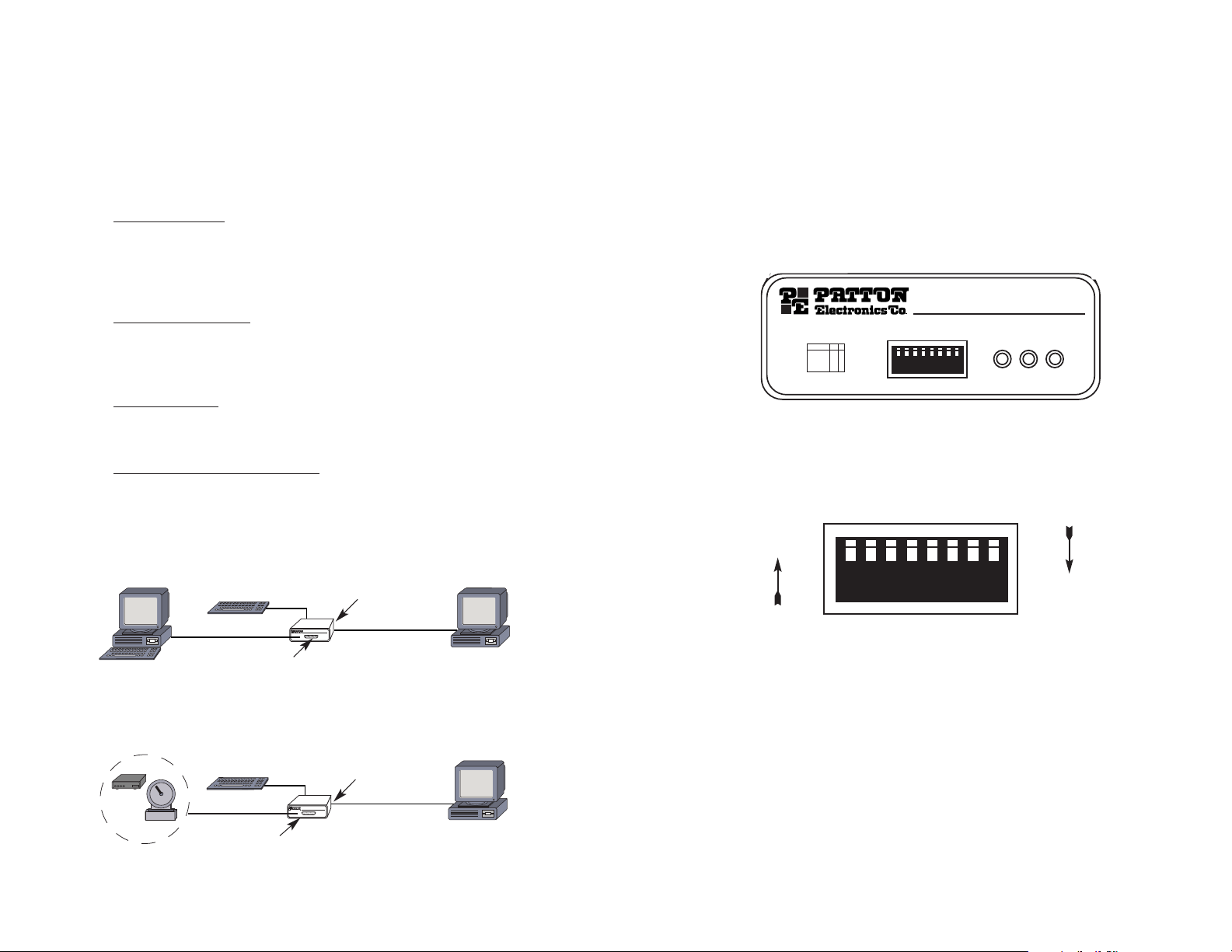
2.0 APPLICATIONS
Model 2003 allows you to connect an RS-232 or RS485 computer
port to another computer’s keyboard port while still using the keyboard.
Typical applications are for:
•
Software Testing With the help of a Model 2003, you can devel-
op a sequence of keystrokes and send them to the keyboard port
of a computer running the software that you want to test.You can
do this without having to add any software or ports to the comput-
er system you are testing.
• Multi-System testing Using the multi-drop capability of the
Model 2003 keyboard port adapter allows centrally controlled testing of up to 58 systems simultaneously. Only the Model 2003 port
adapter allows such flexibility.
• Remote Access The Model 2003 keyboard port adapter allows
remote access to a system where the software does not provide
any other method.
• Monitoring Ke
yboard Sessions
The Model 2003 can be used
to monitor keyboard sessions. This can be helpful to develop
regression test data or to detect keystrokes that are causing problems with target software. Attach a Keyboard to your Computer's
RS-232 Port - You can use the Model 2003 to send and receive
from a Keyboard attached to an RS-232 port.
3.0 CONFIGURATION
The Model 2003 is easy to install and is ruggedly designed for
excellent reliability. The following instructions will help you to properly
configure the Model 2003.
3.1 CONFIGURATION SWITCHES
The Model 2003 has eight DIP switches that you may use to set
the port address and the bit rate. These externally accessible switches
located on the front of the Model 2003 as shown in Figure 3, below.
Figure 4 shows the orientation of the DIP Switches with respect to
Open and Closed positions.
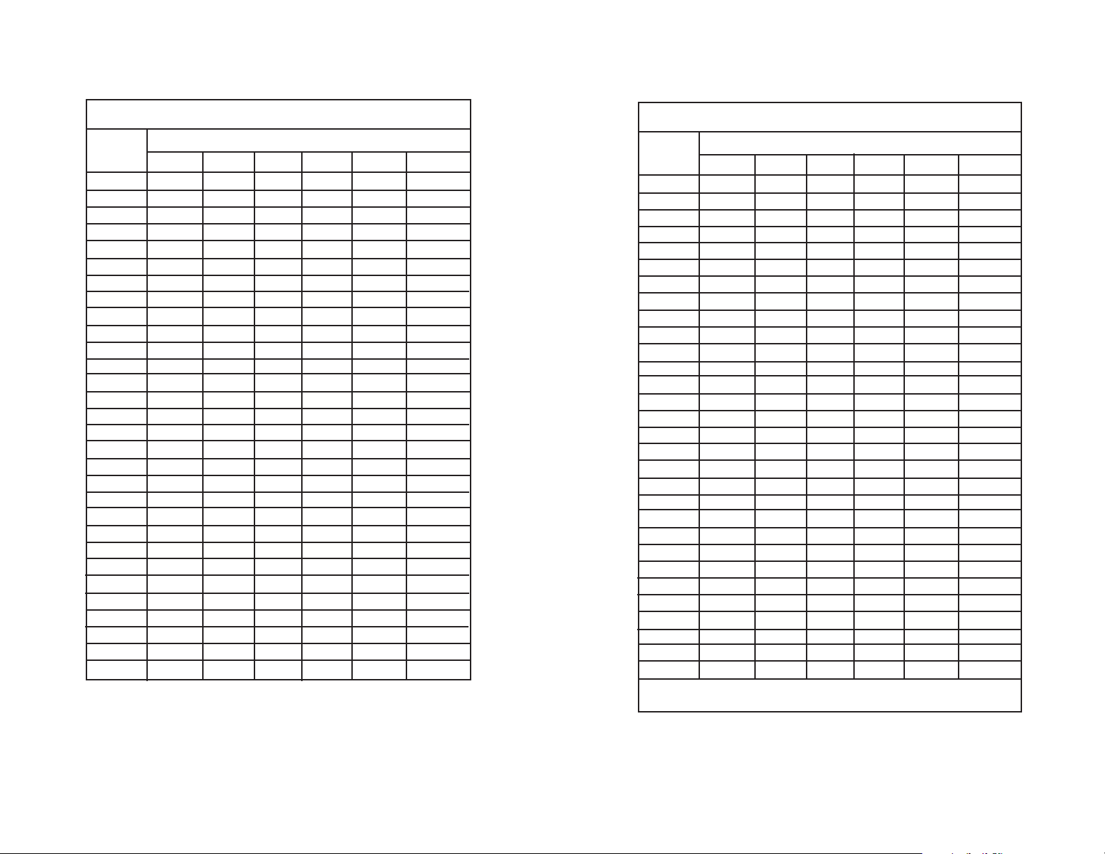
3.1.1 Address Configuration Switches (S1 through S6)
Switches S1-S6 allow you to set an address for the Model 2003.
You must set an address for each Model 2003 configured in a multidrop topology. To set a 2003 address, choose an address from the
left-most column of Table 1. Then configure Switches S1-S6 according
to the the OPEN or CLOSED settings in the same row.
Figure 2. Creating an “extra”RS-232 or RS-485 port for a remote input device
Modem
Patton Model 2003
DIN-5 Cable
AT Keyboard
Host PC
RS-232/RS-485 Port
Scale
Serial Cable
Figure 1. Software testing using a PC program to simulate keystrokes:
PC Running Target Application
AT Keyboard
Serial Cable
Patton Model 2003
PC Running Keystroke Simulation
DIN-5 Cable
RS-232/RS-485 Port
Figure 3. Model 2003 Front Panel Switches
Figure 4. Close-up of DIP Switches Showing Open and Closed Positions
OPEN
CLOSED
Keyboard
Receive
Transmit
Address Rate
1 2 3 4 5 6 7 8
1 2 3 4 5 6 7 8
Data Rate 7 8
9600
4800
2400
1200
O
O
C
C
O
C
O
C
Open =
Closed =
➔
➔
MODEL 2003 RS-232/RS-485
Keyboard Adapter
1 2 3 4 5 6 7 8
7 8
Table 1. Model 2003 Address Settings
ADDRESS
SWITCH SETTINGS
12 34 56
None Open Open Open Open Open Open
1 Closed Open Open Open Open Open
2 Open Closed Open Open Open Open
3 Closed Closed Open Open Open Open
4 Open Open Closed Open Open Open
5 Closed Open Closed Open Open Open
6 Open Closed Closed Open Open Open
7 Closed Closed Closed Open Open Open
8 Open Open Open Closed Open Open
9 Closed Open Open Closed Open Open
10 Open Closed Open Closed Open Open
11 Closed Closed Open Closed Open Open
12 Open Open Closed Closed Open Open
13 Closed Open Closed Closed Open Open
14 Open Closed Closed Closed Open Open
15 Closed Closed Closed Closed Open Open
16 Open Open Open Open Closed Open
17 Closed Open Open Open Closed Open
18 Open Closed Open Open Closed Open
19 Closed Closed Open Open Closed Open
20 Open Open Closed Open Closed Open
21 Closed Open Closed Open Closed Open
22 Open Closed Closed Open Closed Open
23 Closed Closed Closed Open Closed Open
24 Open Open Open Closed Closed Open
25 Closed Open Open Closed Closed Open
26 Open Closed Open Closed Closed Open
27 Closed Closed Open Closed Closed Open
28 Open Open Closed Closed Closed Open
29 Closed Open Closed Closed Closed Open
Table 1. Model 2003 Address Settings (continued)
ADDRESS
SWITCH SETTINGS
12 34 56
30 Open Closed Closed Closed Closed Open
31 Closed Closed Closed Closed Closed Open
32 Open Open Open Open Open Closed
33 Closed Open Open Open Open Closed
34 Open Closed Open Open Open Closed
35 Closed Closed Open Open Open Closed
36 Open Open Closed Open Open Closed
37 Closed Open Closed Open Open Closed
38 Open Closed Closed Open Open Closed
39 Closed Closed Closed Open Open Closed
40 Open Open Open Closed Open Closed
41 Closed Open Open Closed Open Closed
42 Open Closed Open Closed Open Closed
43 Closed Closed Open Closed Open Closed
44 Open Open Closed Closed Open Closed
45 Closed Open Closed Closed Open Closed
46 Open Closed Closed Closed Open Closed
47 Closed Closed Closed Closed Open Closed
48 Open Open Open Open Closed Closed
49 Closed Open Open Open Closed Closed
50 Open Closed Open Open Closed Closed
51 Closed Closed Open Open Closed Closed
52 Open Open Closed Open Closed Closed
53 Closed Open Closed Open Closed Closed
54 Open Closed Closed Open Closed Closed
55 Closed Closed Closed Open Closed Closed
56 Open Open Open Closed Closed Closed
57 Closed Open Open Closed Closed Closed
58 Open Closed Open Closed Closed Closed
*59 Closed Closed Open Closed Closed Closed
*Special Setting 59: Puts Model 2003 in immediate mode with
address of zero (no address).

9 10
3.1.2 Bit Rate Switches (S7 and S8)
Set Switches S7 and S8 together to determine the bit rate (in bits
per second) of the Model 2003.
S7
S8 Bit Rate
Open Open 9600 bps
Closed Open 4800 bps
Open Closed 2400 bps
Closed Closed 1200 bps
3.2 CONFIGURATION STRAPS
In addition to the configuration switches described above, the
Model 2003 also has two internal straps: One that set the RS-232 or
RS-485 Operation; and, one that determines whether the keyboard
connection passes through the 2003, or connects between devices in
parallel. In order to configure these straps, you must open the Model
2003 case.
NOTE: Before opening the case, determine whether the default
settings are correct for your application (see Sections 3.2.3 and
3.2.4)
3.2.1 Opening the Case
To open the Model 2003 insert a large flat head screwdriver into
an open slot on either side of the case, as in Figure 5.
Twist the screwdriver head slightly and the top half of the case will
separate from the lower half, as in Figure 6, below.
To close the case, fit the 2 halves together snugly and snap them
back in place.
Figure 6. Using a the Screwdriver to Open the Plastic Case
Figure 5. Using a Large Flat Blade Screwdriver to Open the Plastic Case

11 12
3.2.2 Jumpers K1 and K2
The internal jumpers mounted on the Model 2003’s PC board
(labeled K1 - K2) are used to configure the RS-232/RS-485 operation
and keyboard operation. Figure 7 (below) shows the location of the
Model 2003’s jumpers on the internal PC board.
Jumper K1: RS-232 or RS-485 Interface
This setting determines whether the the DB-25 operates according
to the RS-232 standard or the RS-485 standard.
K1
Setting
1 & 2 RS-232 Operation
(default position)
2 & 3 RS-485 Operation
Jumper K2: Power via DB-25 Pin 9
Normally, the Model 2003 operates on +5V supplied by the 6 pin
computer’s Mini-DIN keyboard interface. You may also supply operating voltage to pin 9 on the DB-25 connector if you don’t connect the
computer’s Mini-DIN keyboard interface. However, most computers
already supply voltage on pin 9. DO NOT connect this jumper unless
you are not connecting the computer keyboard port AND the RS-232
device does not supply power.
K2 Setting
Strap On Connects +5V from the RS-232 device to pin 9 of the
DB-25 connector
Strap Off Disconnects pin 9 on the DB-25 connector
(default position)
Switch K1
Switch K2
Figure 8. Possible strap positions for jumper K1
Figure 7. Jumpers K1 and K2 on the top of Model 2003 pc board
Rear
Front
1
2
3
1 2
1
2
3
1
2
3
Default
RS-232
RS-485
Toward
Rear
WARNING!! +5V is normally provided by the PC. DO NOT
connect to another +5V source if the PC provides power. This
can result in damage to the RS-232 device and to connecting
equipment.

13 14
4.0 INSTALLATION
The Model 2003 is typically installed by connecting the DB-25 port
to a computer or terminal, the keyboard port to a keyboard, and the
computer port to a computer’s keyboard port. This section describes
connection procedures.
There are three data ports on the rear panel of the Model 2003 -an RS-232/RS-485 female DB-25 port, a Keyboard port, and a computer port (see Figure 9, below).
4.1 CONNECTING RS-232/RS-485 DEVICES
When the DB-25 port of the Model 2003 is configured as an RS232 port, it looks like DCE (Data Circuit-Terminating Equipment).
Therefore, the Model 2003 serial port will connect directly to a DTE
(Data Termination Equipment) The following pinout diagram shows the
signal directions of the pins on the interface.
Pin#
Description Direction
1 Protective Ground N/A
2 Transmit Data RS-232 Input to 2003
3 Receive Data RS-232 Output from 2003
4 Request to Send RS-232 Input to 2003
5 Clear to Send RS-232 Output to 2003
6 Data Set Ready RS-232 Output to 2003
7 Signal Ground (common return)
8 Carrier Detect RS-232 Output from 2003
9 +5VDC RS-232 Input
14 Transmit Data/Receive Data RS-485 Input+/Output+
16 Transmit Data/Receive Data RS-485 Input-/Output20 Data Terminal Ready RS-232 Input to 2003
4.1.1 Connecting RS-232 Terminal Equipment
The diagrams below show pin connections between the Model
2003's serial port and a standard RS-232 serial interfaces. You may
use these diagrams to construct your own cables, or you may purchase
pre-made cables from Patton Electronics.
PC/XT™ to Model 2003 Pin-Outs
Serial DB-25 (DTE) Model 2003 DB-25 (DCE)
Pin No. Pin No.
1 (FG) --------------------------------------- 1
2 (TD) --------------------------------------- 2
3 (RD)--------------------------------------- 3
4 (RTS) ------------------------------------- 4
5(CTS) -------------------------------------- 5
6 (DSR)------------------------------------- 6
7 (SG)--------------------------------------- 7
8 (CD)--------------------------------------- 8
20(DRT) ------------------------------------20
Figure 9. Connection ports on the rear panel of Model 2003
RS - 232 / RS-485
Keyboard Computer
PC/AT™ to Model 2003 Pin-Outs
Serial DB-9 (DTE) Model 2003 DB-25 (DCE)
Pin No. Pin No.
1 (CD) 8 (CD)
2 (RD) 3 (RD)
3 (TD) 2 (TD)
4 (DTR) 20 (DTR)
5 (SG) 7 (SG)
6 (DSR) 6 (DSR)
7 (RTS) 4 (RTS)
8 (CTS) 5 (CTS)
9 (n/c)

15 16
4.1.2 Connecting RS-485 Terminal Equipment
The diagrams below show pin connections between the Model
2003's RS-485 half-duplex serial interface and a typical RS-485 serial
interfaces.You may use these diagrams to construct your own cables,
or you may purchase pre-made cables from Patton Electronics.
Point-To-Point Connection
RS-485 T ransmitter/Receiver Model 2003
(Your Computer) Pin No.
TX+/RX+---------------------------------- 14
TX-/RX- ----------------------------------- 16
Ground---------------------------------------7
4.2 CONNECTING THE COMPUTER/KEYBOARD PORTS
To connect the computer and keyboard’s ports, follow these steps:
1. Connect the keyboard’s 6-Pin Mini-DIN connector to the keyboard port on the Model 2003.
2. Connect the enclosed 6-Pin Mini-DIN cable between the por t
labeled “Computer” on the Model 2003 to the Target PC’s
Keyboard DIN port.
5.0 OPERATION
5.1 COMMAND/DATA ENTRY
The Model 2003’s main job is to accept data from the RS-232 or
RS-485 port and send it through to another computer's keyboard port.
However you may also enter configuration commands to the Model
2003. You may send data or commands in the following forms:
1. ASCII;
2. ASCII control codes;
3. DOS scan codes;
4. Keyboard scan codes;
5. ASCII Hexadecimal.
Commands are instructions to the Model 2003 to do something
other than just pass data through to the computer. All commands
begin with a ~ (tilde, hex 7E) character followed by a command character and in some cases, some data.
: ~C<ENTER> {Sets Model 2003 to Character Mode}
: DIR^M<ENTER> {Sends DOS a directory command}
5.1.1 Command Entry Rules
Commands have some restrictions based upon the Model 2003
operating Model (See Section 5.2 for Operating Modes). These rules
are listed below:
Rule #1.
You may string commands together in one command
line, and separate commands with spaces. This will occur before
you press <ENTER/CR>.
Rule #2.
Each command line must end with an <ENTER/CR>.
The Model 2003 will not begin command execution until it receives
a carriage-return character.
Rule #3. If you turn on line tur n around (~L Command) or set an
address on the Model 2003 if the Model 2003 is addressed, a line
can have a maximum length of 46 characters and should end with
an <ENTER> (CR, hex 0D).
Rule #4. In the case when immediate tur n around is set, data and
commands are interpreted as received, and buffered up to 30
characters.
Rule #5. If you get more than 30 characters ahead of the computer, the additional characters will be tossed.
Multi-Point Connection
RS-485 Transmitter/Receiver First Model 2003
(Your Computer) Pin No.
TX+/RX+---------------------------------- 14
TX-/RX ------------------------------------ 16
Ground---------------------------------------7
Additional
Model 2003s
Pin No.
--------------------14
----------------16
--------------7

17 18
Rule #6. Characters are not echoed when the Model 2003 is
addressed.
Rule #7. If line tur n around is set or if the Model 2003 is
addressed, a colon is sent back acknowledging the data sent.
Rule #8. After receiving an addressed message, a colon is sent
back immediately.
Rule #9. If not addressed but line turn around is set, a colon is
sent back after the data has been processed, signaling that another command can be sent.
5.2 OPERATING MODES
Four operating mode commands set the way Model 2003 interprets incoming data. Once set, the Model 2003 operating mode stays
the same until you change it or until a power failure occurs.
~C Character Mode - is the default mode of operation. When
this mode is set, any ASCII character except ~ (tilde, hex 7E),
^ (caret, hex 5E), and CR (return, hex 0D) is converted to the
scan codes for that character. Each ASCII character will be
sent to the keyboard with the corresponding make and
release codes. Allow enough time for the codes to be sent
through to the computer, as an ASCII code can require up to
10 keyboard codes to execute.
(default operating mode)
Control codes may be sent by a combination of a ^ (caret, hex
5E),a nd the corresponding letter. For example, a control C
(Hex 03) is ^C.
~H Hex ASCII Mode - Data is interpreted as hexadecimal encod-
ed ASCII. For example, to send the computer the character
‘A’, you would need to send its hexadecimal ASCII value (Hex
41) as two ASCII digits, 4 and 1.
~S Scan Code Mode - In this mode, date is translated to the cor-
responding keyboard scan codes. For an ASCII transfer, each
pair of ASCII encoded characters is interpreted as a DOS
scan code. For a binary transfer, each 8 bit character is interpreted as a DOS scan code. DOS assigns each key a DOS
scan code. Note that all DOS scan codes are sent complete
with make and break sequences.
~K Key Code Mode - In this mode, codes are sent directly to the
computer without interpretation. For an ASCII transfer, each
pair ASCII encoded characters is interpreted as a keyboard
code. For a binary transfer, each 8 bit character is interpreted
as a keyboard code. Care should be taken in using keyboard
scan codes, as the computer can be left in a very confused
state if the scan code sequence is not properly completed.
5.3 DATA TRANSFER COMMANDS
~A ASCII Transfer - Default setting. If ASCII transfer is set, all
data is interpreted as ASCII.
~B Binary Transfer - In scan code (~S) or key code (~K) modes.
Data is sent as 8 bit binary
5.4 KEYBOARD COMMANDS
~Dnn Set/Clear Keyboard LEDs - Use this command to turn on or
off local keyboard LED indicators. The nn field is an ASCII
hex encoded binary field, where:
b0 = Scroll Lock
b1 = Num Lock
b2 = Caps Lock
Examples: ~D01 Scroll Lock on, Caps & Num Lock off
~D04 Caps Lock on, Scroll & Num Lock off
~D00 Turns off all LEDs
~Xnn Send Data to Keyboard - Use this command to send the
ASCII hex encoded byte nn to the keyboard. This command
requires technical knowledge of the keyboards.
5.5 TURN AROUND COMMANDS
~I Immediate Turn Around - Data is interpreted ‘on-the-fly’.
Special address switch setting of 59 makes this default for
non-addressed mode. Note that in this mode <ENTER/CR>
(Hex 0D) is not a special character, and passed on to the
computer.
~L Line Turn Around - Set Model 2003 to a line oriented basis,
each line ending with an <ENTER/CR> (Hex 0D).

19 20
~Pnn Set Turn Around Delay (nn milliseconds) - This sets the
delay that the Model 2003 waits before sending data in
response to a command. The default setting in nonaddressed mode is 0, and in addressed mode the default setting is 3 milliseconds. (NOTE: You must send two digits, i.e.
for 7 milliseconds, send ~P07)
5.6 KEYBOARD MONITOR COMMANDS
~M Monitor ON - Turns keyboard monitor on
~N Monitor OFF - Tur ns keyboard monitor off
5.7 OTHER COMMANDS
~T Test Model 2003 - This command to the Model 2003 causes
it to undergo tests to validate the keyboard and computer
interface. You will see the keyboard LED’s cycle, testing the
keyboard interface. You should see on the PC screen:
TEST:7 (With the number cycling from 0-7)
The serial port displays:
Test: <ENTER> to stop
The test runs until <ENTER> is received.
~? Request Status - The format of the response is:
AA-EEDDMBTV where
AA is the address setting
- is a dash character, Hex 2D
EE is a error status:
00-No Errors 01-Parity Error
02-Framing Error 03-Parity and Framing
DD LED status (bit field -0=OFF, 1=ON
b0-Scroll lock b1=Num Lock b2=Caps
Lock
M Mode setting (~C, ~H, ~K, or ~S)
B Binar y or ASCII Transfer Setting (~A or ~B)
T Turn Around Setting (~I or ~L)
V Monitor Setting (~M or ~N)
5.8 MULTIDROP OPERATION
If the DIP switch address setting is not zero, Model 2003 looks for
an address select prefix to any buffer received. The address must be
the first byte of the transmission and the high bit set. Address 1 is hex
81, Address 2 is hex 82, etc. If you send a command to address 80,
all Model 2003s will read the command.
When sending data to the Model 2003 in multi-drop mode, the
Model 2003 will return a single byte colon character when it receives
the message. This does not mean that you can send another buffer
can be sent but rather that the Model 2003 received the message and
the host can go on to talk to other devices. If a proper delay cannot be
assured, you should poll the device until it responds before sending
another buffer.
5.9 LED INDICATORS
The Model 2003 features three front panel LEDs that monitor data
activity on the keyboard and RS-232/RS-485 ports. Figure 10 shows
the front panel location of each LED. Following Figure 10 is a description of each LEDs function.
Keyboard Turns solid yellow when the keyboard is
sending to the Computer. Blinks whenever
the Model 2003 is processing a command
from the RS-232/485 port. If Model 2003 is
set with an address, the LED blinks yellow
when it receives its address.
Receive Blinks red when Model 2003 receives data
or commands on the RS-232/RS-485 port.
Transmit Blinks green when Model 2003 transmits
data through the RS-232/RS-485 port.
Figure 3. Model 2003 Front Panel Switches
Keyboard
Receive
Transmit
Address Rate
1 2 3 4 5 6 7 8
1 2 3 4 5 6 7 8
Data Rate 7 8
9600
4800
2400
1200
O
O
C
C
O
C
O
C
Open =
Closed =
➔
➔
MODEL 2003 RS-232/RS-485
Keyboard Adapter

21 22
APPENDIX A
PATTON ELECTRONICS MODEL 2003
SPECIFICATIONS
Transmission Format: Asynchronous, half duplex
Data Rates: 1200, 2400, 4800 and 9600 bps
Serial Interface: RS-232 or RS-485
(jumper selectable)
Connectors: RS-232 and RS-485 (DB-25F)
Two Mini-DIN 6 pin Connectors:
(1) to keyboard
(2) to computer
LED Indicators: Keyboard, Receive, and Transmit
Codes Accepted: Character, HEX ASCII, Scan Code,
and Key Code
Multiple Drops: Supports 58 addressable units in
an RS-485 multipoint environment
Data T urnaround Modes: Line Oriented or Immediate
Power Supply: Interface Powered, obtains
operating power from data and
control signals
Temperature Range: 32 to 122ºF (0 to 50º C)
Dimensions: 1.58”H x 4.16”W x 3.75"D
(10.6 x 4.1 x 8.8 cm)
APPENDIX B
PATTON ELECTRONICS MODEL 2003
SCAN CODES
AT SCAN
2003 KEYBOARD
CODE
SC CODE
KEY SCAN CODES
01 01 ES C 76 F0 76
02 02 1/! 16 F0 1E
03 03 2/@ 1E F0 1E
04 04 3 /# 26 F0 26
05 05 4 /$ 25 F0 25
06 06 5/% 2E F0 2E
07 07 6 / ^ 36 F0 36
08 08 7/& 3D F0 3D
09 09 8/ * 3E F0 3E
10 10 9 / ( 46 F0 46
11 11 0 / ) 45 F0 45
12 12 4E F0 4E
13 13 55 F0 55
14 14 Backspace 66 F0 66
15 15 Tab 0D F0 0D
16 16 Q 15 F0 15
17 17 W 1D F0 1D
18 18 E 24 F0 24
19 19 R 2D F0 2D
20 20 T 2C F0 2C
21 21 Y 35 F0 35
22 22 U 3C F0 3C
23 23 I 43 F0 43
24 24 O 44 F0 44
25 25 P 4D F0 4D
26 26 [/{ 54 F0 54
27 27 ]/} 5B F0 5B
28 28 Enter 5A F0 5A
28 A0 Keypad Enter E0 5A E0 F0 5A
29 29 Left Ctrl 14 F0 14
29 A 1 Right Ctrl E0 14 E0 F0 14
29+69 A2 PAUSE E1 14 77 E1 F0 14 F0 77
30 30 A 1C F0 1C
31 31 S 1B F0 1B
32 32 D 23 F0 23
33 33 F 2B F0 2B
--/_
=/+

23 24
APPENDIX B
PATTON ELECTRONICS MODEL 2003
SCAN CODES (continued)
APPENDIX B
PATTON ELECTRONICS MODEL 2003
SCAN CODES (continued)
AT SCAN
2003 KEYBOARD
CODE
SC CODE
KEY SCAN CODES
33 33 F 2B F0 2B
34 34 G 34 F0 34
35 35 H 33 F0 33
36 36 J 3B F0 3B
37 37 K 42 F0 42
38 38 L 4B F0 4B
39 39 ;/: 4C F0 4C
40 40 52 F0 52
41 41 0E F0 0E
42 42 Left Shift 12 F0 12
43 43 \/| 5D 50 5D
44 44 Z 1A F0 1A
45 45 Z 22 F0 22
46 46 C 21 F0 21
47 47 V 2A F0 2A
48 48 B 32 F0 32
49 49 N 31 F0 31
50 50 M 3A F0 3A
51 51 , / < 41 F0 41
52 52 . / > 49 F0 49
53 53 / / ? 4A F0 4A
53 93 / E0 4A E0 F0 4A
54 54 Right Shift 59 F0 59
55 55 * 7C F0 7C
55 A4 PRT SCRN E0 1 2 E0 7C E0 F0 7C E0 F0 12
56 A5 Right Alt 11 F0 11
57 57 Space E0 11 E0 F0 11
58 58 Caps Lock 29 F0 29
59 59 F1 58 F0 58
60 60 F2 05 F0 05
61 61 F3 06 F0 06
62 62 F4 0C F0 0C
63 63 F5 03 F0 03
64 64 F6 0B F0 0B
65 65 F7 83 F0 83
66 66 F8 0A F0 0A
‘/”
`/~
AT SCAN
2003 KEYBOARD
CODE
SC CODE
KEY SCAN CODES
67 67 F9 01 F0 01
68 68 F10 09 F0 09
69 69 NUM LOCK 77 F0 77
70 70 SCROLL LOCK 7E F0 7 E
7 1 7 1 HOME E0 6 C E 0 F0 6 C
71 A6 Keypad Home/7 C6 F0 6C
72 72 Up Arrow E0 12 E0 75 E0 F0 75 E0 F0 12
72 A7 Keypad Up Arrow/8 75 F0 75
73 73 Page Up E0 7D E0 F0 7D
73 A8 Keypad PageUp/9 7D F0 7D
74 74 - 7B F0 7B
75 75 Left Arrow E0 12 E0 6B E0 F0 6B E0 F0 12
75 A9 Keypad Left Arrow/4 6B F0 6B
76 76 05 73 F0 73
77 77 Right Arrow E0 12 E0 74 E0 F0 74 E0 F0 12
77 B0 Keypad Rt. Arrow/6 74 F0 74
78 78 + 79 F0 79
79 79 End E0 12 E0 69 E0 F0 69 E0 F0 12
79 B1 End/1 69 F0 69
80 80 Down Arrow E0 12 E0 72 E0 F0 72 E0 F0 12
80 B2 Keypad Dn Arrow/2 72 F0 72
81 81 Page Down E0 12 E0 7A E0 F0 7A E0 F0 12
81 B3 Keypad PageDown/3 7A F0 7A
82 8 2 Insert E 0 70 E0 F0 70
82 B 4 Ins/0 7 0 F0 70
83 83 Delete E0 12 E0 71 E0 F0 72 E0 F0 12
83 B5 Keypad Del/. 71 F0 71
84 Undefined
85 Undefined
86 Undefined
87 87 F11 78 F0 78
88 88 F12 07 F0 07
89 Undefined
90 90 Left Window E0 5B E0 F0 5B
91 91 Right Window E0 5C E0 F0 5C
92 92 Menu E0 5D E0 F0 5D

25 26
APPENDIX C
PATTON ELECTRONICS MODEL 2003
ASCII SCANS CODES
APPENDIX C
PATTON ELECTRONICS MODEL 2003
ASCII SCANS CODES (continued)
ASCII ASCII KEYBOARD
CHAR. HEX SCAN CODES
NUL ^@ O O 14 1E F0 1E F0 14
SOH ^A O1 14 1C F0 1C F0 14
STX ^B O2 14 32 F0 32 F0 14
ETX ^C O3 14 21 F0 21 F0 14
EOT ^D O4 14 23 F0 23 F0 14
ENQ ^E O5 14 24 F0 24 F0 14
ACK ^F O6 14 2B F0 2B F0 14
BEL ^G O7 14 34 F0 34 F0 14
BS ^H O8 66 F0 66
TAB ^I O9 0D F0 0D
LF ^J 0A 14 3B F0 3B F0 14
VT ^K 0B 14 42 F0 42 F0 14
FF ^L 0C 14 4B F0 4B F0 14
CR ^M 0D 3A F0 3A
SO ^N 0E 14 31 F0 31 F0 14
SI ^O 0F 14 44 F0 44 F0 14
DLE ^P 10 14 4D F0 4D F0 14
DC1 ^Q 11 14 15 F0 15 F0 14
DC2 ^R 12 14 2D F0 2D F0 14
DCE ^S 13 14 1B F0 1B F0 14
DC4 ^T 14 14 2C F0 2C F0 14
NAK ^U 15 14 3C F0 3C F0 14
SYN ^V 16 14 2A F0 2A F0 14
ETB ^W 17 14 1D F0 1D F0 14
EM ^X 18 14 22 F0 22 F0 14
SUB ^Y 19 14 35 F0 35 F0 14
SUB ^Z 1A 14 1A F0 1A F0 14
ESC ^[ 1B 76 F0 76
FS ^\ 1C 14 5D F0 5D F0 14
GS ^] 1D 14 5B F0 5B F0 14
RS ^^ 1E 14 12 36 F0 36 F0 12 F0 14
US ^_ 1F 14 12 4E F0 4E F0 12 F0 14
Space 20 29 F0 29
! 21 12 16 F0 16 F0 12
" 22 12 52 F0 52 F0 12
# 23 12 26 F0 26 F0 12
$ 24 12 25 F0 25 F0 12
ASCII ASCII KEYBOARD
CHAR. HEX SCAN CODES
% 25 12 2E F0 2E F0 12
& 26 12 3D F0 3D F0 12
27 52 F0 52
( 28 12 46 F0 46 F0 12
) 29 12 45 F0 45 F0 12
* 2A 7C F0 7C
+ 2B 79 F0 79
, 2C 41 F0 41
- 2D 7B F0 7B
. 2E 49 F0 49
/ 2F 4A F0 4A
0 30 45 F0 45
1 31 16 F0 16
2 32 1E F0 1E
3 33 26 F0 26
4 34 25 F0 25
5 35 2E F0 2E
6 36 36 F0 36
7 37 3D F0 3D
8 38 3E FO 3E
9 39 46 F0 46
: 3A 12 4C F0 4C F0 12
; 3B 4C F0 4C
< 3C 12 41 F0 41 F0 12
= 3D 12 55 F0 55 F0 12
> 3E 12 49 F0 49 F0 12
? 3F 12 4A F0 4A F0 12
@ 40 12 1E F0 1E F0 12
A 41 12 1C F0 1C F0 12
B 42 12 32 F0 32 F0 12
C 43 12 21 F0 21 F0 12
D 44 12 23 F0 23 F0 12
E 45 12 24 F0 24 F0 12
F 46 12 2B F0 2B F0 12
G 47 12 34 F0 34 F0 12
H 48 12 33 F0 33 F0 12
I 49 12 43 F0 43 F0 12

27 28
APPENDIX C
PATTON ELECTRONICS MODEL 2003
ASCII SCANS CODES (continued)
APPENDIX C
PATTON ELECTRONICS MODEL 2003
ASCII SCANS CODES (continued)
Copyright © 1998
Patton Electronics Company
All Rights Reserved
ASCII ASCII KEYBOARD
CHAR. HEX SCAN CODES
J 4A 12 3B F0 3B F0 12
K 4B 12 42 F0 42 F0 12
L 4C 12 4B F0 4B F0 12
M 4D 12 3A F0 3A F0 12
N 4E 12 31 F0 31 F0 12
O 4F 12 44 F0 44 F0 12
P 50 12 4D F0 4D F0 12
Q 51 12 15 F0 15 F0 12
R 52 12 2D F0 2D F0 12
S 53 12 1B F0 1B F0 12
T 54 12 2C F0 2C F0 12
U 55 12 3C F0 3C F0 12
V 56 12 2A F0 2A F0 12
W 57 12 1D F0 1D F0 12
X 58 12 22 F0 22 F0 12
Y 59 12 35 F0 35 F0 12
Z 5A 12 1A F0 1A 0 12
[ 5B 54 F0 54
\ 5C 5D F0 5D
] 5D 5B F0 5B
^ 5E 12 36 F0 36 F0 12
_ 5F 12 4E F0 4E F0 12
` 60 0E F0 0E
a 61 1C F0 1C
b 62 32 F0 32
c 63 21 F0 21
d 64 23 F0 23
e 65 24 F0 24
f 66 2B F0 2B
g 67 34 F0 34
h 68 33 F0 33
i 69 43 F0 43
j 6A 3B F0 3B
k 6B 42 F0 42
l 6C 4B F0 4B
m 6D 3A F0 3A
n 6E 31 F0 31
ASCII ASCII KEYBOARD
CHAR. HEX SCAN CODES
o 6F 44 F0 44
p 70 4D F0 4D
q 71 15 F0 15
r 72 2D F0 2D
s 73 1B F0 1B
t 74 2C F0 2C
u 75 3C F0 3C
v 76 2A F0 2A
w 77 1D F0 1D
x 78 22 F0 22
y 79 35 F0 35
z 7A 1A F0 1A
{ 7B 12 54 F0 54 F0 12
| 7C 12 5D F0 5D F0 12
} 7D 12 5B F0 5B F0 12
~ 7E 12 0E F0 0E F0 12
Del 7F 71 F0 71
 Loading...