

Page 1
USER
MANUAL
MODEL 2002 Series
RS-232 to TTL
Interface Converter
CERTIFIED
An ISO-9001
Certified Company
Part# 07M2002-A
Doc#
07725U2-001,
Rev. B
Revised 1/23/08
SALES OFFICE
(301) 975-1000
TECHNICAL SUPPORT
(301) 975-1007
http://www.patton.com
Page 2

1.0 WARRANTY INFORMATION
Patton Electronics warrants all Model 2002 components to be
free from defects, and will--at our option--repair or replace the product
should it fail within one year from the first date of shipment.
This warranty is limited to defects in workmanship or materials, and
does not cover customer damage, abuse, or unauthorized modification.
If this product fails or does not perform as warranted, your sole
recourse shall be repair or replacement as described above. Under no
condition shall Patton Electronics be liable for any damages incurred
by the use of this product. These damages include, but are not limited
to, the following: lost profits, lost savings, and incidental or
consequential damages arising from the use of or inability to use this
product. Patton Electronics specifically disclaims all other warranties,
expressed or implied, and the installation or use of this product shall be
deemed an acceptance of these terms by the user.
1.1 RADIO AND TV INTERFERENCE
The Models 2002 generates and uses radio frequency energy, and
if not installed and used properly--that is, in strict accordance with the
manufacturer's instructions--may cause interference to radio and
television reception. The Model 2002 has been tested and found to
comply with the limits for a Class A computing device in accordance
with the specifications in Subpart J of Part 15 of FCC rules, which are
designed to provide reasonable protection from such interference in a
commercial installation. However, there is no guarantee that
interference will not occur in a particular installation. If the Model 2002
does cause interference to radio or television reception, which can be
determined by disconnecting the RS-232 or TTL interface, the user is
encouraged to try to correct the interference by one or more of the
following measures: moving the computing equipment away from the
receiver, re-orienting the receiving antenna, and/or plugging the
receiving equipment into a different AC outlet (such that the computing
equipment and receiver are on different branches).
1.2 CE NOTICE
The CE symbol on your Patton Electronics equipment indicates
that it is in compliance with the Electromagnetic Compatibility (EMC)
directive and the Low Voltage Directive (LVD) of the Union European
(EU). A Certificate of Compliance is available by contacting Technical
Support.
1
Page 3

1.3 SERVICE
All warranty and non-warranty repairs must be returned freight
prepaid and insured to Patton Electronics. All returns must have a
Return Materials Authorization number on the outside of the shipping
container. This number may be obtained from Patton Electronics
Technical Support: (301) 975-1007; http://www.patton.com; or,
support@patton.com.
NOTE: Packages received without an RMA number will not be
accepted.
Patton Electronics' technical staff is also available to answer any
questions that might arise concerning the installation or use of your
Model 2002. Technical Support hours: 8AM to 5PM EST, Monday
through Friday.
2
Page 4

2.0 GENERAL INFORMATION
Thank you for your purchase of this Patton Electronics product.
This product has been thoroughly inspected and tested and is
warranted for One Year parts and labor. If any questions or problems
arise during installation or use of this product, please do not hesitate to
contact Patton Electronics Technical Support at (301)-975-1007.
2.1 FEATURES
• Bi-directional, asynchronous data conversion between RS-232
and TTL
• Supports data rates to 230 kbps
• Two versions available:
Model 2002FC-MT connects an RS-232 DTE to a TTL DCE
Model 2002FT-MC connects an RS-232 DCE to a TTL DTE
• Passes TD & RD plus five control signals: CD, DTR, DSR, CTS &
RTS
• Data and control signals independently selectable for
inverting/non-inverting
• Interface powered–no AC required
• RS-232 interface is a DB-25 female, TTL interface is a DB-25 male
2.2 DESCRIPTION
The Patton Model 2002 RS-232 to TTL Interface Converter lets
an asynchronous RS-232 device communicate bi-directionally with an
asynchronous TTL device. Supporting data rates up to 230 kbps, the
Patton Model 2002 passes data (TD, RD) plus five control signals (CD,
DTR, DSR, CTS and RTS). In addition, the Patton Model 2002 allows
data and control signals to be independently jumper-selected as
“inverting” or “non-inverting.”
The Patton Model 2002 is available in two versions: DCE-to-DTE
and DTE-to-DCE. The RS-232 interface is presented on a DB-25
female connector, while the TTL interface is presented on a DB-25
male connector. Deriving power from the data and control signals, the
Patton Model 2002 requires no AC power or batteries for operation.
3
Page 5
3.0 CONFIGURATION
The Model 2002 is very easy to use. Most applications require no
configuration. Just plug it in and go! However, some TTL circuitry
requires data and/or control signals to be inverted (opposite) from their
normal conditions. Please read the section below to determine if the
default settings will work for you.
3.1 DEFAULT TTL LOGIC LEVELS
Systems represents data signals by alternating between “mark”
(binary “1”) and space (binary “0”) conditions. TTL (Transistor-Transitor
Logic) circuitry normally a represents a “mark” as a voltage between
2.4 and 5.0 Volts, and a “space” as a voltage between 0.4 and 0.4
Volts. By contrast, TTL control signals (RTS, CTS, DSR, DCD and
DTR) are either “active” (between 0.0 and 0.4 Volts), or “inactive”
(between 2.4 and 5.0 Volts). Table 1, below, summarizes the above
information.
Table 1. Default TTL Signal Levels
Signal Level Data Signals Control Signals
0.0 to 0.4 Volts space active
2.4 - 5.0 Volts mark inactive
Table 1, above, shows the default configuration of the Model 2002.
In most cases no modification is required!!
circuitry requires inverted signals for either the data or control signals,
you must change the settings of one or two jumper switches. In order
to change the jumper settings, you must open the case. Please follow
the instructions below to do so.
However, if your TTL
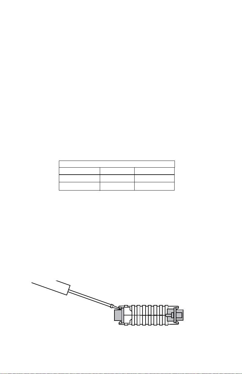
3.2 OPENING THE CASE
TheJP1 and JP2 jumpers on the Model 2002 are located on the
PC board. To open, insert a small flathead screw driver or similar tool
between the DB-25 female connector and the lip of the case as shown
in Figure 1.
Figure 1: Using a Small Screw Driver to Open the Model 2002 Case
4
Page 6

Then
gently
twist the screw driver to pop the case open as shown
in Figure 2. Be careful not to damage the case or connector as you
twist the screw driver.
Figure 2: Using a Small Screw Driver to Open the Model 2002 Case
3.3 CHANGING THE JUMPER STRAPS
Once you have opened the case of the Model 2002, you will see
two jumper straps located the top side of the PC board (See Figure 3,
below.
TTL Side
(Male)
RS-232 Side
(Female)
JP1
JP2
Figure 3: Close-Up of the Model 2002 Series Jumper Straps
To change the jumper strap settings, simply remove the jumpers
and replace them on the jumper posts as described in the following
section.
5
Page 7

3.1 JUMPER SWITCHES JP1 AND JP2
Use Jumper Switches JP1 and JP2 to control the logic state of the
data and/or control signals.
required!!
Consult the user manual of the TTL device or the device’s
In most cases no modification is
manufacturer before changing the settings on JP1 and JP2. This
section describes the jumper settings.
Non-Inverted Data and Control Signals
(Default Setting)
Position JP1 and JP2 vertically on the jumper posts to select noninverted data and control signals (default setting). Figure 4 shows the
position of the jumpers on the pc board. Table 3 shows the relative
signal levels.
JP1 JP2
TTL Side
RS-232 Side
Figure 4: Non-Inverted Data and Control Signal Jumpers
Table 3. Non-Inverted Data and Control
Signal Level Data Signals Control Signals
0.0 to 0.4 Volts space active
2.4 - 5.0 Volts mark inactive
6
Page 8
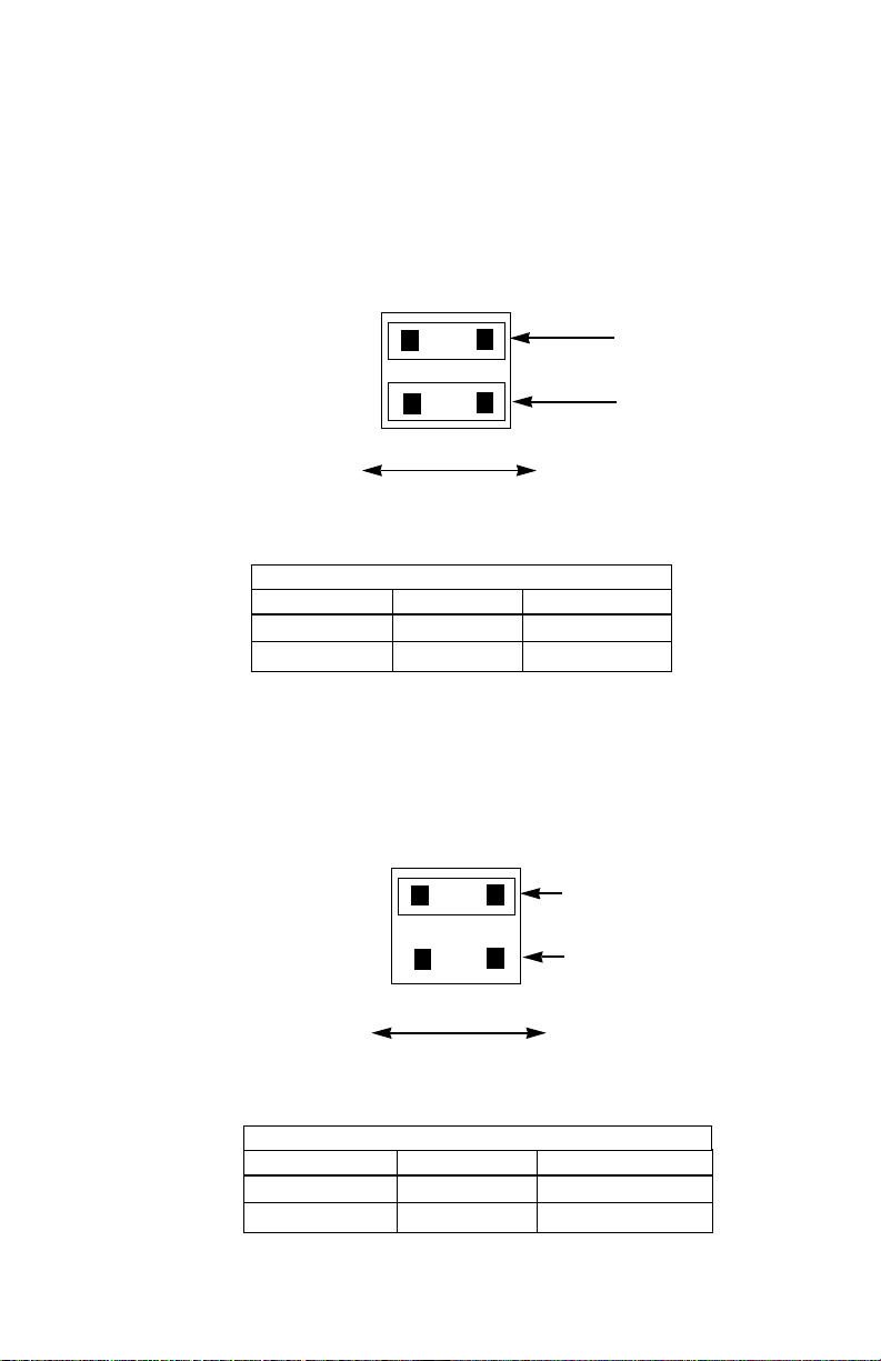
Inverted Data and Control Signals
Position JP1 and JP2 horizontally on the jumper posts to select
inverted data and control signals. Figure 5 shows the position of the
jumpers on the pc board. Table 4 shows the relative signal levels.
JP1
JP2
TTL Side
RS-232 Side
Figure 5: Inverted Data and Control Signal Jumpers
Table 4. Inverted Data and Control Signals
Signal Level Data Signals Control Signals
0.0 to 0.4 Volts mark inactive
2.4 - 5.0 Volts space active
Inverted Data and Non-Inverted Control Signals
Position JP1 horizontally top jumper posts and remove JP2 to
select inverted data and non-inverted control signals. Figure 6 shows
the position of the jumpers on the pc board. Table 5 shows the relative
signal levels.
JP1
JP2
TTL Side
RS-232 Side
Figure 6: Inverted Data and Non-Inverted Control Signal Jumpers
Table 5. Inverted Data, Non-Inverted Control Signals
Signal Level Data Signals Control Signals
0.0 to 0.4 Volts mark active
2.4 - 5.0 Volts space inactive
7
Page 9

Inverted Control and Non-Inverted Data Signals
Position JP2 horizontally on bottom jumper posts to select inverted
control and non-invert data signals. Figure 7 shows the position of the
jumpers on the pc board. Table 6 shows the relative signal levels.
JP1
JP2
TTL Side
RS-232 Side
Figure 7: Inverted Control and Non-Inverted Data Signal Jumpers
Table 6. Inverted Control, Non-Inverted Data Signals
Signal Level Data Signals Control Signals
0.0 to 0.4 Volts space inactive
2.4 - 5.0 Volts mark active
8
Page 10
3.0 INSTALLATION
The Patton Model 2002 is very simple to install. Just plug it in like
a normal cable and you're ready to go. Since the Model 2002 is
available in two gender and DTE/DCE orientations, many applications
are possible.
NOTE: The Model 2002 Series always uses a DB-25 female
connector on the RS-232 interface and a DB-25 male connector on
the TTL Interface.
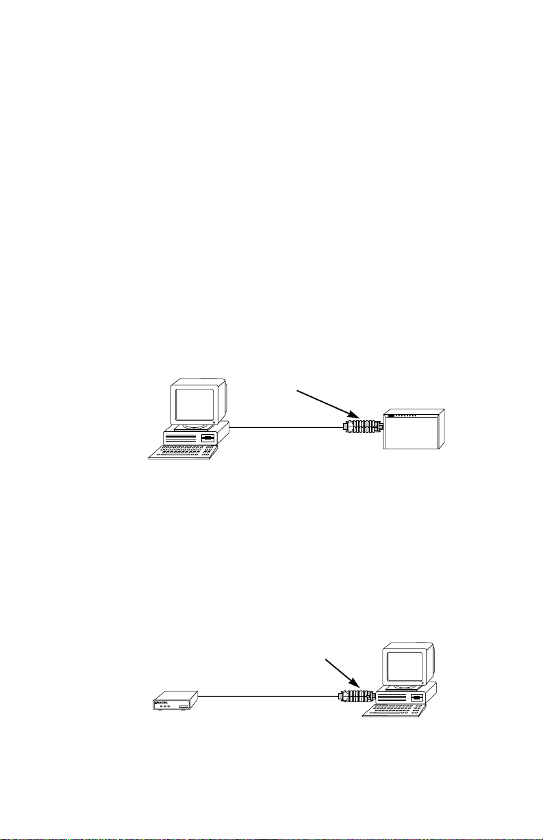
4.1 CONNECTING THE MODEL 2002FC-MT
Connect the 25 pin male port (TTL side) directly to a TTL DCE
device. Connect the 25 pin female port (RS-232 side) of Model
2002FC-MT to an RS-232 DTE device using a straight-through cable of
the shortest possible length (less than 50 feet). Figure 8 shows a
typical application of the 2002FC-MT.
RS-232
DTE
2002FC-MT
TTL DCE
Figure 8: Connecting the Model 2002FC-MT
4.2 CONNECTING THE MODEL 2002FT-MC
Connect the 25 pin male port (TTL side) directly to a TTL DTE
device. Connect the 25 pin female port (RS-232 side) of the Model
2202FT-FC to an RS-232 DCE device using a straight-through cable of
the shortest possible length (less than 50 feet). Figure 9 shows the
typical application of the 2002FT-MC.
TTL DTE
RS-232
DCE
2002FT-MC
Figure 9. Connecting the Model 2002FT-MC
9
Page 11

APPENDIX A
MODEL 2002 SERIES SPECIFICATIONS
Transmission Format: Asynchronous
Data Rate: 0 to 230 kbps
Interface: Serial TTL or serial RS-232; DCE-to-
DTE or DTE- to-DCE
Connectors: RS-232 interface, DB-25 female; TTL
interface, DB-25 male
Control Signals Supported: CD, DTR, DSR, CTS and RTS, passed
directly through
Signal Inversion: data signals and control signals can be
independently configured for “inverting”
or “non-inverting” using internal
jumpering
Power Supply: none required, draws all necessary
operating power from RS-232 and TTL
data and control signals
Temperature Range: 32 to 122ºF (0 to 50º C)
Dimensions: 2.2" x 2.1" x 0.7" (5.6 x 5.3 x 1.8 cm)
10
Page 12
APPENDIX B
PATTON MODEL 2002 INTERFACE PIN ASSIGNMENTS
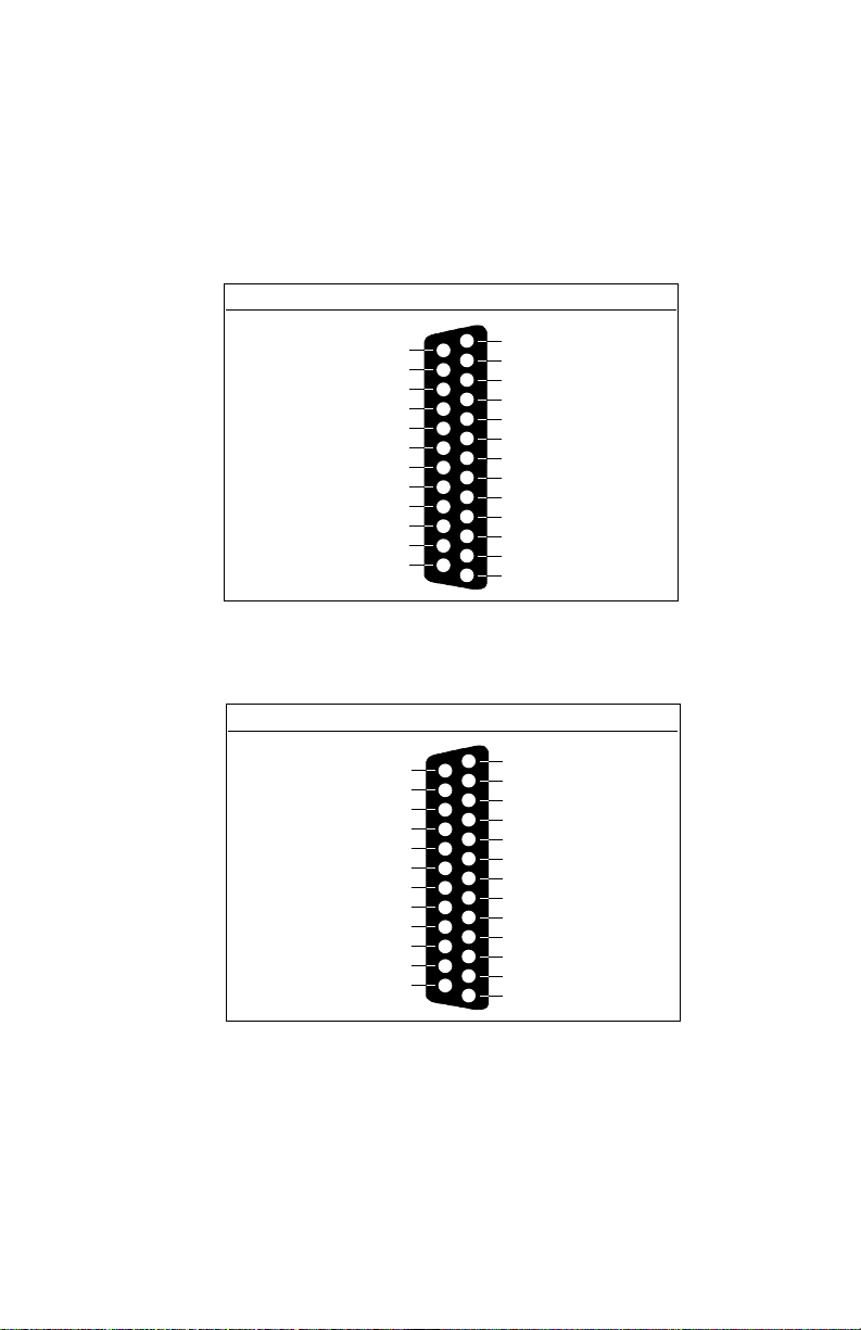
RS-232 INTERFACE
1- (FG) Frame Ground
2- (TD) Transmit Data
3- (RD) Receive Data
4- (RTS) Request to Send
5- (CTS) Clear to Send
6- (DSR) Data Set Ready
Data Term. Ready (DTR) - 20
TTL INTERFACE
Data Term. Ready (DTR) - 20
7- (SG) Signal Ground
8- (DCD) Data Carrier Detect
9 (DCV+) Aux Power*
1- (FG) Frame Ground
2- (TD) Transmit Data
3- (RD) Receive Data
4- (RTS) Request to Send
5- (CTS) Clear to Send
6- (DSR) Data Set Ready
7- (SG) Signal Ground
8- (DCD) Data Carrier Detect
9 (DCV+) Aux Power*
11
Page 13
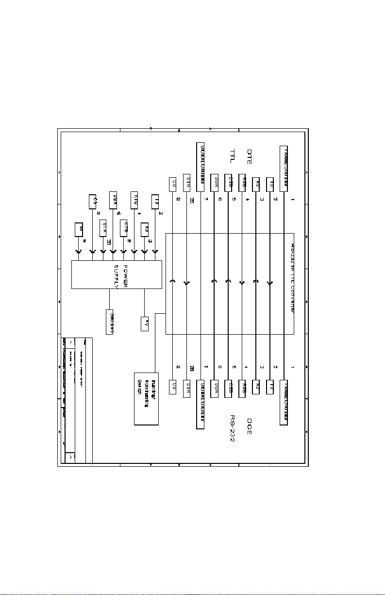
APPENDIX C
MODEL 2002FC-MT BLOCK DIAGRAM
12
Page 14

APPENDIX D
MODEL 2002FT-MC BLOCK DIAGRAM
13
Page 15

An ISO-9001
Certified Company
Dear Valued Customer,
Thank you for purchasing Patton Electronics products! We do
appreciate your business. I trust that you find this user manual helpful.
We manufacture one of the widest selections of data communications
products in the world including CSU/DSU's, network termination units,
powered and self-powered short range modems, fiber optic modems, interface
converters, baluns, electronic data switches, data-line surge protectors,
multiplexers, transceivers, hubs, print servers and much more. We produce
these products at our Gaithersburg, MD, USA, facility, and can custom
manufacture products for your unique needs.
We would like to hear from you. Please contact us in any of the
following ways to tell us how you like this product and how we can meet your
product needs today and in the future.
Web: http://www.patton.com
Sales E-mail: sales@patton.com
Support E-mail: support@patton.com
Phone - Sales (301) 975-1000
Phone - Support (301) 975-1007
Fax: (301) 869-9293
Mail: Patton Electronics Company
7622 Rickenbacker Drive
Gaithersburg, MD 20879 USA
We are committed to a quality product at a quality price. Patton
Electronics is ISO 9001 certified. We meet and exceed the highest standards
in the industry (CE, UL, etc.).
It is our business to serve you. If you are not satisfied with any
aspect of this product or the service provided from Patton Electronics or its
distributors, please let us know.
Thank you.
Burton A.Patton
Vice President
P.S. Please tell us where you purchased this product:
_________________________________________________________
_________________________________________________________
_________________________________________________________
_________________________________________________________
_________________________________________________________
_________________________________________________________
Page 16

 Loading...