

Page 1
USER
MANUAL
MODEL 1226
Parallel Short
Range Modem
SALES OFFICE
(301) 975-1000
TECHNICAL SUPPORT
(301) 975-1007
http://www.patton.com
Part# 07M1226-B
Doc# 104031UB
Revised 08/13/99
Page 2

1.0 WARRANTY INFORMATION
Patton Electronics warrants all Model 1226 components to be
free from defects, and will—at our option—repair or replace the product
should it fail within one year from the first date of shipment.
This warranty is limited to defects in workmanship or materials, and
does not cover customer damage, abuse or unauthorized modification.
If this product fails or does not perform as warranted, your sole
recourse shall be repair or replacement as described above. Under no
condition shall Patton Electronics be liable for any damages incurred
by the use of this product. These damages include, but are not limited
to, the following: lost profits, lost savings and incidental or
consequential damages arising from the use of or inability to use this
product. Patton Electronics specifically disclaims all other warranties,
expressed or implied, and the installation or use of this product shall be
deemed an acceptance of these terms by the user.
1.1 RADIO AND TV INTERFERENCE
The Model 1226 generates and uses radio frequency energy, and if
not installed and used properly—that is, in strict accordance with the
manufacturer's instructions—may cause interference to radio and
television reception. The Model 1226 is designed to provide
reasonable protection from such interference in a commercial
installation. However, there is no guarantee that interference will not
occur in a particular installation. If the Model 1226 does cause
interference to radio or television reception, which can be determined
by disconnecting the parallel interface, the user is encouraged to try to
correct the interference by one or more of the following measures:
moving the computing equipment away from the receiver, re-orienting
the receiving antenna and/or plugging the receiving equipment into a
different AC outlet (such that the computing equipment and receiver are
on different branches).
1.2 SERVICE
All warranty and non-warranty repairs must be returned freight
prepaid and insured to Patton Electronics. All returns must have a
Return Materials Authorization number on the outside of the shipping
container. This number may be obtained from Patton Electronics
Technical Service at (301) 975-1007.
Packages received without an
RMA number will not be accepted.
Patton Electronics' technical staff is also available to answer any
questions that might arise concerning the installation or use of your
Model 1226. Technical Service hours: 8AM to 5PM EST, Monday
through Friday.
1
2.0 GENERAL INFORMATION
Thank you for your purchase of this Patton Electronics product.
This product has been thoroughly inspected and tested and is
warranted for One Year parts and labor. If any questions or problems
arise during installation or use of this product, please do not hesitate to
contact Patton Electronics Technical Support at (301) 975-1007.
2.1 FEATURES
• Extends parallel communication to 14 miles
• Data rates to 57.6 Kbps
• Operates over two shielded or unshielded twisted pair
• Allows devices to communicate in “real time”
• Acts as either a transmitter or a receiver
• Compatible with most printer sharing devices
• Compensates for low power parallel printer interfaces
• DB-25 parallel connections
• RJ-11, RJ-45 or terminal block line connections
• Surge protection and optical isolation
2.2 DESCRIPTION
The Patton Electronics Model 1226 parallel short range modem
allows a PC and a parallel output device (printer, sharing switch, etc.) to
communicate at distances to 14 miles over two shielded or unshielded
twisted pair. Externally powered, the Model 1226 supports serial data
rates to 57.6 Kbps, which is fast enough to allow “real time” parallel
communication. The Model 1226 features high speed Silicon
Avalanche Diode surge protection, which intercepts transient surges
and shunts them safely to chassis ground. Optical isolation gives the
Model 1226 immunity to ground loops that would otherwise hamper
between-building communications.
The Model 1226 always works in pairs: One unit is plugged into
the PC’s parallel port and a second unit is plugged into the output
device’s parallel port. Since the Model 1226 can act as either a
transmitter or a receiver unit, you do not have to purchase a special
“transmit” or “receive” unit. The Model 1226 can also be teamed up
with a Model 1060 for bi-directional parallel to serial transmission.
The Model 1226 receiver comes equipped with DB-25 parallel
interface. Line connection options are RJ-11, RJ-45 or terminal block.
2
Page 3
3.0 CONFIGURATION
The Model 1226 is simple to install, and is designed for excellent
reliability: just set it and forget it. The following instructions will help
you set up and install the Model 1226 properly. If you have any
questions, please call Patton Technical Support at (301) 975-1007.
3.1 CONNECTING TWO MODEL 1226s
(Parallel to Parallel)
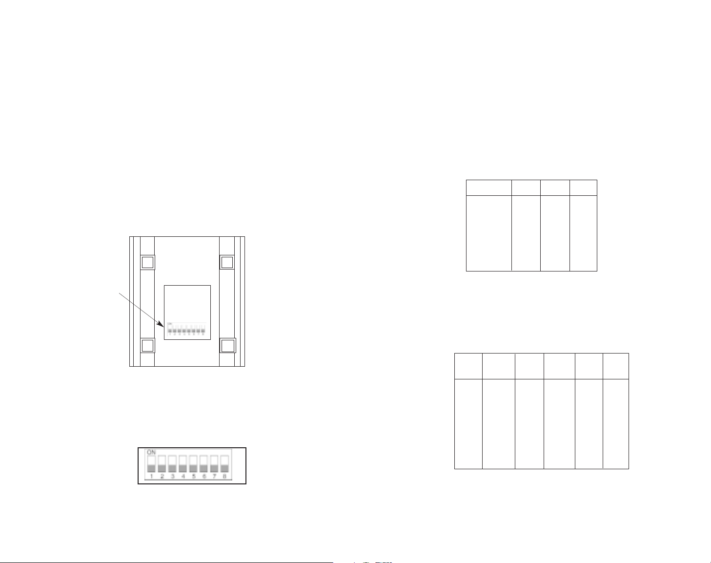
The Model 1226 uses a set of eight DIP switches (see Figure 1)
that allow configuration to a wide range of applications. Because all
eight switches are in one externally accessible DIP switch package,
there is no need to open the Model 1226's case for configuration. The
configuration switches allow you to select data rates, parity, word length
and flow control selection. The following section describes all switch
locations, positions and functions.
The Model 1226 uses a DIP switch package (see Figure 2). To
configure your unit, use a small screwdriver and gently push each
switch to its proper setting. The ON and OFF positions are shown in
Figures 1 and 2.
3
3.1.1 DETAILED SWITCH SETTINGS
This section provides detailed information about the function of
each DIP switch and lists all possible settings.
Switches 1 through 3: Frequency and Data Rate
Switches 1 through 3 determine the data rate for the Model 1226.
Use the following chart to configure your equipment:
NOTE: Factory defaults are in
bold italics.
Switch 4 through 6: Data, Parity and Stop Bit
Switches 4 through 6 are used to specify the data, parity and stop
bits. The following table shows the settings that may be used:
NOTE: Factory defaults are in
bold italics.
4
Figure 1. Underside of the Model 1226, showing location of DIP switches
Figure 2. Close-up of the Model 1226 configuration switch package
1200 ON OFF OFF
2400 ON OFF ON
4800 OFF ON ON
9600
ON ON OFF
19200 ON ON ON
38400 OFF OFF OFF
57600 OFF OFF ON
Data Rate SW1 SW2 SW3
FRONT
REAR
DIP Switches
7B EP 1S ON ON ON
7B OP 1S ON ON OFF
7B NP 2S ON OFF ON
7B EP 2S ON OFF OFF
7B OP 2S OFF ON ON
8B EP 1S OFF ON OFF
8B OP 1S OFF OFF ON
8B NP 1S
OFF OFF OFF
Stop
Data Parity Bit SW4 SW5 SW6
Page 4

Switch 7: Reserved for Future Use
Switch 8: Hardware/Software Control
The setting for Switch 8 determines whether the Model 1226 uses
either hardware or software flow control.
NOTE: Factory defaults are in
bold italics.
3.2 CONNECTING A MODEL 1226 TO A MODEL 1060
(Parallel to Serial/ Serial to Parallel)
When connecting a Model 1226 to a Model 1060, you need to
configure both units. First, set the DIP switches on the Model 1226 as
indicated in Section 3.1.1. Then configure the Model 1060 by following
the instructions below.
3.2.1 USING THE MODEL 1060 AS A TRANSMITTER
If you are using your Model 1060 as a transmitter, you must
configure the Model 1060 according to the chart below. Do not change
the settings on your Model 1226.
Next, you will need to configure your computer’s settings. If you
are using DOS, type the following command at the C prompt:
MODE COM2: 9600,n,8,1,p
If you are not using DOS, call Patton Technical Support at
(301) 975-1007 for further assistance.
5
3.2.2 USING THE MODEL 1060 AS A RECEIVER
If you are using your Model 1060 as a receiver, you must configure
the Model 1060 according to the chart below. Do not change the
settings on your Model 1226.
6
Control Control Carrier Switch Settings
Mode Input Output Controlled
(DCE/DTE) (C
In
)(COut) by (CIn)1234567
DCE 4, 11, 20 8 Enabled OFF ON ON ON OFF OFF ON
DCE 4, 11, 20 6 Enabled OFF OFF OFF ON ON ON ON
Control Control Carrier Switch Settings
Mode Input Output Controlled
(DCE/DTE) (C
In
)(COut) by (CIn)1234567
DTE 5, 6, 8 4 Enabled OFF ON ON ON OFF OFF ON
DTE 5, 6, 8 11, 20 Enabled OFF OFF OFF ON ON ON ON
Hardware
OFF
Software ON
Flow Control SW8
Page 5

4.0 INSTALLATION
The Model 1226 is designed to be easy to use. After configuring
the DIP switches, connect the two twisted pairs using one of three
methods: RJ-11 jack, RJ-45 jack or terminal blocks. Figure 3 shows
the location of the RJ-11 jack, RJ-45 jack or terminal blocks, as well as
the female DB-25 connector, on the rear of the Model 1226.
The Model 1226 operates over 4-wire twisted pair. The two pair
must be 26 AWG or larger “dry”, unconditioned, metallic wire. Dial-up
analog circuits, such as those used with a standard Hayes type
modem, are not acceptable. The twisted pair may be shielded or
unshielded. Both types yield favorable results. You will need a pair of
Model 1226s for each circuit—one at each end of the circuit.
4.1 TWISTED PAIR CONNECTION USING RJ-11 OR RJ-45
The RJ-11 and RJ-45 connectors on the Model 1226’s twisted pair
interface are pre-wired for a standard TELCO wiring environment. The
signal/pin relationships are shown on the following table:
RJ-11 SIGNAL RJ-45 SIGNAL
1 ---------GND 1---------------NC
2 ---------RCV- 2---------------GND
3 ---------XMT+ 3---------------RCV4 ---------XMT- 4---------------XMT+
5 ---------RCV+ 5---------------XMT6 ---------GND 6---------------RCV+
7---------------GND
8---------------NC
When connecting two Model 1226s, it is necessary to use a “crossover” cable. The diagram below shows how a crossover cable should
be constructed for an environment where both Model 1226s use a
4-wire RJ-11 or RJ-45 connector (RJ-45 is shown below). Similar logic
should be followed when using RJ-11 connectors or a combination of
the two.
SIGNAL PIN# PIN# SIGNAL
GND
‡
2 7---------------------GND
‡
RCV- 3 5---------------------XMT-
XMT+ 4 6---------------------RCV+
XMT- 5 3---------------------RCV-
RCV+ 6 4---------------------XMT+
GND
‡
7 2---------------------GND
‡
†
Standard color codes—yours may be different
‡
Connection to ground is optional
Figure 4. AT&T Standard Pin Assignements
4.2 FOUR-WIRE CABLE CONNECTION VIA TERMINAL BLOCKS
If you are not going to use the modular jacks, then follow the
instructions below.
A. Locate the terminal block on the back of the unit. It should look like
the following diagram:
B. Connect one pair of wires to XMT+ and XMT- (transmit positive
and transmit negative) on the terminal block, making careful note
of which color is positive and which color is negative.
7 8
1 - Blue
2 - Orange
3 - Black
4 - Red
5 - Green
6 - Yellow
7 - Brown
8 - Slate
1 - Blue
2 - Yellow
3 - Green
4 - Red
5 - Black
6 - White
RX+ RX- GND TX- TX+
Figure 3. Rear view of the Model 1226
Powered Short Range
Modem
Power
RX+ RX- GND TX- TX+
Parallel Interface
Made In The USA
LINE
Page 6

C. Connect one pair of wires to RCV+ and RCT- (receive positive and
receive negative) on the terminal block, making careful note of
which color is positive and which color is negative.
D. If there is a shield around the telephone cable, it may be connected
to “G” on the terminal block. To avoid ground loops, we
recommend connecting the shield at the computer end only. A
ground wire is not necessary for proper operation of these units.
E. When you have finished connecting the telephone line to units at
both ends, it should look similar to the following diagram:
5.0 OPERATION
Once both Model 1226s have been connected to each other and to
their corresponding parallel input and output devices, you are ready to
operate the units. The units should function transparently, just like a
cable. There is no ON / OFF switch.
5.1 LED STATUS MONITORS
The Model 1226 features six front panel status LEDs that indicate
the condition of the modem and communication link. Figure 5 shows
the front panel location of each LED. Following Figure 5 is a
description of each LED's function.
● The “Power” LED glows solid green when power is applied to the
Model 1226.
● The “TD” indicator blinks red and green with data activity. Red
indicates that the Model 1226 is not currently transmitting data.
● The “RD” indicator blinks red and green with data activity. Red
indicates that the Model 1226 is not currently receiving data.
● The “Control In” indicator usually glows green. However, it glows
solid red when flow control comes from the remote Model 1226.
● The “Control Out” indicator usually glows green. However, it glows
solid red when flow control comes from the local Model 1226.
● The “Status” indicator shows data activity by blinking green in a
variety of codes. The chart on the following page describes these
codes:
9 10
Figure 5. The Model 1226’s front panel LEDs
XMT + RCV+
XMT - RCV GG
RCV - XMT RCV + XMT +
To Shield (Optional)
}
One Pair
}
One Pair
Model 1226 Parallel Short Range Modem
Control
Control
IN
Power TD RD
OUT
Status
Page 7

5.2 POWER-UP
Apply AC power to the Model 1226 by plugging the separate AC
power adapter into the rear panel outlet of the Model 1226, and then
into an acceptable AC power outlet. Make sure you connect the parallel
side first, then the line side. There is no power switch on the Model
1226; when the “Power” LED is lit, the Model 1226 is powered up.
When the local and remote Model 1226s are both powered up and
passing data normally, the following LEDconditions will exist:
● PWR = Green
● TD & RD = Red or blinking red/green
● CTL IN & CTL OUT = Green
● Status = Blinking green
APPENDIX A
SPECIFICATIONS
Parallel Interface: DB-25 female
Data Rate: Up to 57.6 Kbps
Range: Up to 14 miles
Transmission: Full duplex over 4-wire shielded or
unshielded twisted pair
Line Interface: RJ-11,RJ-45 or terminal block
Surge Protection: 600W power dissipation at 1mS and
response time less than 1.0pS
LED Indicators: Power, TD, RD, Ctl-In, Ctl-Out, Status
Optical Isolation: 2500 V RMS
Power: 10 V AC transformer (110 or 220)
Dimensions: 5.90”l x 4.17”w x 1.61”h
Weight: Approximately 16 oz.
11 12
LED Codes
● ● — ● ——— ● ● — ● ——— Computer is sending data
● ——— ● ——— ● ——— Unit is powered up and initialized;
computer is not sending data
● ● ——— ● ● ——— Parallel device is connected;
computer is not sending data
● — ● ——— ● — ● ——— Printer not ready, data held in buffer
● ● ● ● ———● ● ● ● Computer ignoring flow control, data lost
Key:
● Blink
— Short pause
——— Long pause
Page 8

APPENDIX B
PARALLEL PIN CONFIGURATIONS
APPENDIX C
BLOCK DIAGRAM
11- Busy (Active HIGH) Printer
10- Acknowledge (Active LOW) Printer
9- Data Bit 8 (MSB) Computer
8- Data Bit 7 Computer
7- Data Bit 6 Computer
6- Data Bit 5 Computer
5- Data Bit 4 Computer
4- Data Bit 3 Computer
3- Data Bit 2 Computer
2- Data Bit 1 (LSB) Computer
1- Data Strobe (Active LOW) Computer
SOURCE TRANSMITTER / RECEIVER (DB-25) SOURCE
Common Return / Ground -25
Common Return / Ground -24
Common Return / Ground -23
Common Return / Ground -22
Common Return / Ground -21
Common Return / Ground -20
Common Return / Ground -19
Common Return / Ground -18
13 14
 Loading...