

Page 1
USER
MANUAL
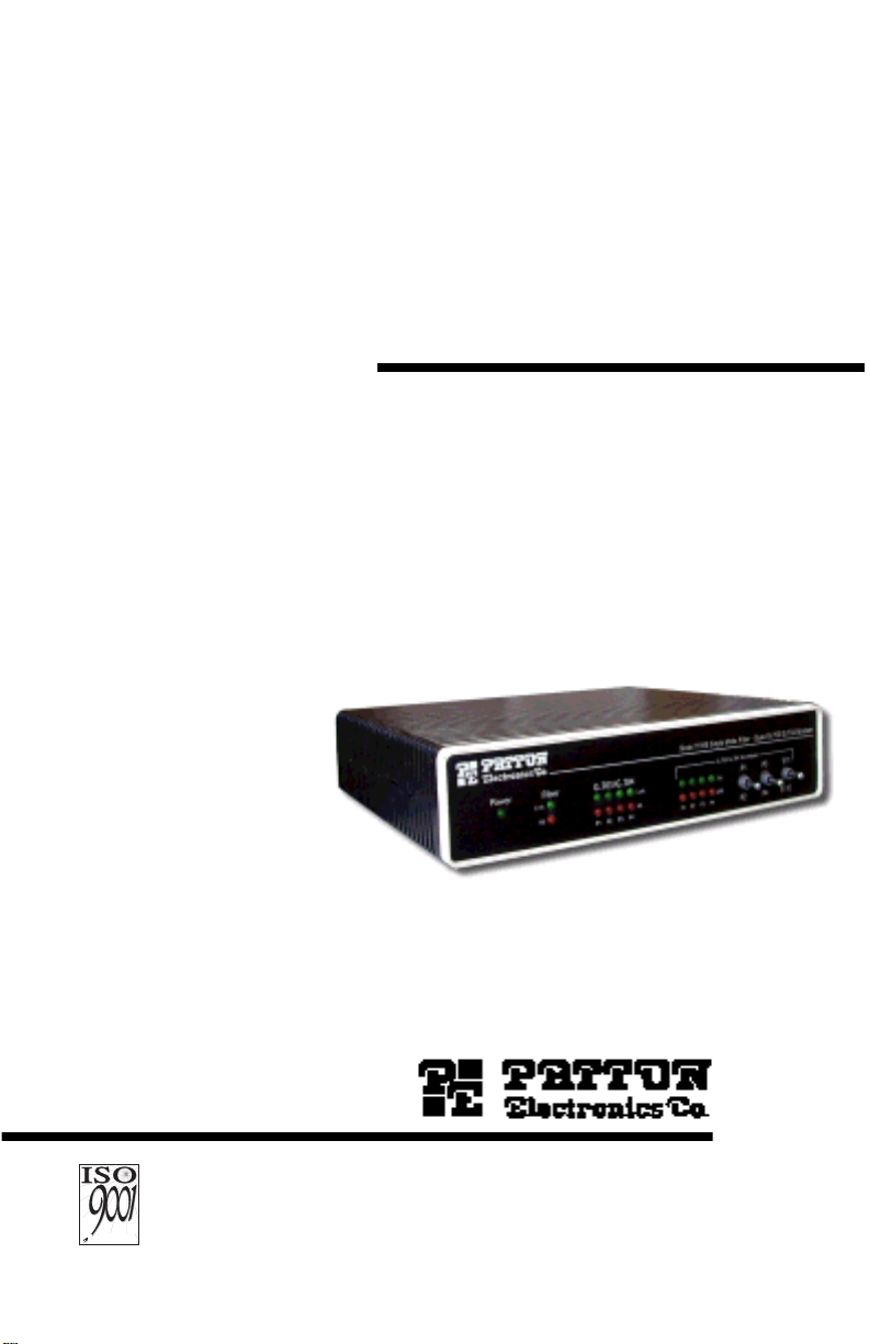
MODEL 1194
Single Mode Fiber
Modem With Four
Fixed E1/T1
Interfaces
CERTIFIED
An ISO-9001
Certified
Company
Part# 07M1194-A
Doc# 017151UA
Released 06/04/01
SALES OFFICE
(301) 975-1000
TECHNICAL SUPPORT
(301) 975-1007
Page 2

TABLE OF CONTENTS
1.0 Warranty Information .................................................................. 4
1.1 Industry Canada Notice................................................................ 4
1.2 FCC Information ........................................................................... 5
1.3 DC Power Notice.......................................................................... 5
1.4 Patton Contact Information........................................................... 6
1.5 FCC Part 68 Compliance Statement (1194/T1)............................ 6
1.6 CE Notice...................................................................................... 7
1.7 Service.......................................................................................... 7
2.0 General Information..................................................................... 8
2.1 Features........................................................................................ 8
2.2 Description.................................................................................... 8
3.0 Configuration............................................................................. 10
3.1 Configuring the Hardware DIP Switches .................................... 10
Configuring DIP switch S1.......................................................... 11
Switch S1-1: Line Coding Options ....................................... 11
Switches S1-2 and S1-3: Line Build Out ............................. 12
Switches S1-6 and S1-7: Clock Mode ................................. 12
Configure DIP switch S2............................................................. 13
Switch S2-1: Local/Remote Loop ........................................ 13
Switch S2-7: Response to RDL ........................................... 13
Switch S2-8: Front Panel Switches ..................................... 13
4.0 Installation.................................................................................. 14
4.1 Connect the G.703/G.704 or T1 Network................................... 14
4.2 Connect the Fiber Interface........................................................ 14
4.3 Power Connection ...................................................................... 15
Connecting to an AC Power Source........................................... 15
Connecting to a DC Power Source............................................. 16
5.0 Power-up .................................................................................... 17
6.0 LED Status Monitors ................................................................. 18
7.0 Test Modes................................................................................. 19
7.1 Local Loopback Test................................................................... 19
7.2 Remote Loopback Test............................................................... 20
7.3 The V.52 Test Pattern Generator ............................................... 21
A Model 1194 Quad E1/T1 to Single Mode
Fiber Specifications................................................................... 22
A.1 Configuration ...............................................................................22
A.2 Clocking Modes ...........................................................................22
A.3 Network ports specifications .......................................................22
Network Line Rate...................................................................... 22
Transmit Line Buildout (T1)........................................................ 22
Interface...................................................................................... 22
Line coding................................................................................. 22
Isolation...................................................................................... 22
2
Page 3

Physical Connection................................................................... 22
A.4 Fiber Port Specifications ..............................................................23
Fiber Line Coding....................................................................... 23
Fiber Physical............................................................................. 23
A.5 Diagnostics ..................................................................................23
A.6 Compliance .................................................................................23
A.7 Laser Safety .................................................................................23
A.8 Network Line Interface .................................................................23
A.9 Power ...........................................................................................23
A.10 Temperature Range .....................................................................23
A.11 Altitude .........................................................................................23
A.12 Humidity .......................................................................................24
A.13 Dimensions ..................................................................................24
A.14 Weight ..........................................................................................24
A.15 Mean Time Between Failure (MTBF) ...........................................24
3
Page 4

1.0 WARRANTY INFORMATION
Patton Electronics
defects, and will—at our option—repair or replace the product should it
fail within one year from the first date of shipment.
This warranty is limited to defects in workmanship or materials, and does
not cover customer damage, abuse or unauthorized modification. If this
product fails or does not perform as warranted, your sole recourse shall
be repair or replacement as described above. Under no condition shall
Patton Electronics
product. These damages include, but are not limited to, the f ollo wing: lost
profits, lost savings and incidental or consequential damages arising
from the use of or inability to use this product.
cifically disclaims all other warranties, expressed or implied, and the
installation or use of this product shall be deemed an acceptance of
these terms by the user.
1.1 INDUSTRY CANADA NOTICE
The Canadian Department of Communications label identifies certified
equipment. This certification means that the equipment meets certain
telecommunications network protective, operational and safety requirements. The Department does not guarantee the equipment will operate
to the user's satisfaction. Before installing this equipment, users should
ensure that it is permissible to be connected to the facilities of the local
telecommunications company. The equipment must also be installed
using an acceptable method of connection. In some cases, the company’s inside wiring associated with a single line individual service may
be extended by means of a certified connector assembly (telephone
extension cord). The customer should be aware that compliance with the
above condition may not prevent degradation of service in some situations. Repairs to some certified equipment should be made by an authorized maintenance facility designated by the supplier. Any repairs or
alterations made by the user to this equipment, or equipment malfunctions, may give the telecommunications company cause to request the
user to disconnect the equipment. Users should ensure f or their o wn protection that the ground connections of the power utility, telephone lines
warrants all Model 1194 components to be free from
be liable for any damages incurred b y the use of this
Patton Electronics
spe-
4
Page 5

and internal metallic water pipe system, are connected together. This
protection may be particularly important in rural areas.
Users should not attempt to make such connections
themselves, but should contact the appropriate electric
inspection authority, or electrician, as appropriate.
Caution
1.2 FCC INFORMATION
This equipment has been tested and found to comply with the limits for a
Class A digital device, pursuant to P art 15 of the FCC Rules. These limits
are designed to provide reasonable protection against harmful interference when the equipment is operated in a commercial environment. This
equipment generates, uses, and can radiate radio frequency energy and,
if not installed and used in accordance with the instruction manual, may
cause harmful interference to radio communications. Operation of this
equipment in a residential area is likely to cause harmful interference in
which case the user will be required to correct the interference at his own
expense. If this equipment does cause harmful interference to radio or
television reception, which can be determined by turning the equipment
off and on, the user is encouraged to try to correct the interference by
one or more of the following measures:
• Reorient or relocate the receiving antenna
• Increase the separation between the equipment and receiver
• Connect the equipment into an outlet on a circuit different from that to
which the receiver is connected
Use of controls or adjustments or performance of
procedures other than those specified herein may result
in hazardous laser radiation exposure.
Caution
1.3 DC POWER NOTICE
Connect the equipment to a 36–60 volts direct-current (VDC), 340 mA
source that is electrically isolated from the AC source. The 36–60 VDC
source
must
be connected to a reliable earth ground.
5
Page 6

An approved external SELV power supply that incorporates a disconnect
device must be used and positioned within reach of the operator’ s position.
1.4 PATTON CONTACT INFORMATION
If you have an y troub le operating the Model 1194, please contact
Electronics T echnical Support
pany may ask you to disconnect the equipment from the telephone network until the problem has been corrected or until you are certain that
the Model 1194 is not malfunctioning. In accordance with FCC rules and
regulation CFR 47 68.218(b)(6), you must notify the telephone company
prior to disconnection.
The following information may be required when applying to your local
telephone company for leased line f acilities. The Univ ersal Service Order
Code (USOC) is RJ-48C. The Facility Interface Codes (FIC) are 04DU9BN, 04DU9-DN, 04DU9-1KN, and 04DU9-1SN. The Service Order Code
(SOC) is 6.0N.
at
301-975-1000
. The telephone com-
Patton
Facility
Service
1.544 Mbps SF format without line
power
1.544 Mbps SF and B8ZS without line
power
1.544 Mbps ANSI ESF without line
power
1.544 Mbps ANSI ESF and B8ZS
without line power
1.5 FCC PART 68 COMPLIANCE STATEMENT (1194/T1)
This equipment complies with Part 68 of FCC Rules. Please note the
following:
1. You are required to request service from the telephone company
before you connect the CSU to a network. When you request service, you must provide the telephone company with the following
data. When you request T1 Service, you must pro vide the telephone
company with the Facility Interface Code. Provide the telephone
company with both of the following codes: 04DU9-B (1.544 MB D4
framing format) and 04DU9-C (1.544 MB ESF format). The telephone company will select the code it has available. The Service
Order Code(s) (SOC): 6.0N. The required Universal Service Order
Code (USOC) jack: RJ 48C. The make, model number, and FCC
Registration number of the CSU.
Interface
Code
04DU9-BN 6.0N RJ48C
04DU9-DN 6.0N RJ48C
04DU9-1KN 6.0N RJ48C
04DU9-1SN 6.0N RJ48C
Service
Code
Network
Connection
6
Page 7

2. Your telephone company may make changes to its facilities, equip-
ment, operations, or procedures that could affect the proper functioning of your equipment. The telephone company will notify you in
advance of such changes to give you and opportunity to maintain
uninterrupted telephone service.
3. If your CSU causes harm to the telephone network, the telephone
company may temporarily discontinue your service. If possible, they
will notify you in advance, but if advance notice is not practical, you
will be notified as soon as possible and will be informed of your right
to file a complaint with the FCC.
4. If you experience trouble with the CSU, please contact Patton Elec-
tronics, Co. for service or repairs. Repairs should be performed only
by Patton Electronics Co.
5. You are required to notify the telephone company when you discon-
nect the CSU from the network.
1.6 CE NOTICE
The CE symbol on your Patton Electronics equipment indicates that it is
in compliance with the Electromagnetic Compatibility (EMC) directive
and the Low Voltage Directive (LVD) of the European Union (EU). A Certificate of Compliance is available by contacting Technical Support.
1.7 SERVICE
All warranty and non-warranty repairs must be returned freight prepaid
and insured to Patton Electronics. All returns must have a Return Materials Authorization number on the outside of the shipping container. This
number may be obtained from Patton Electronics Technical Service at:
tel:
(301)975-1007
E-mail:
support@patton.com
URL:
www.patton.com
Note
Packages received without an RMA number will not be
accepted.
Patton Electronics’ technical staff is also a v ailable to ans wer any questions
that might arise concerning the installation or use of your Model 1194.
Technical Service hours:
8AM to 5PM EST , Monday through Friday
.
7
Page 8
2.0 GENERAL INFORMATION
Thank you for your purchase of this Patton Electronics product. This
product has been thoroughly inspected and tested and is warranted for
One Year parts and labor. If any questions or problems arise during
installation or use of this product, please do not hesitate to contact
Patton Electronics Technical Support at (301) 975-1007
.
2.1 FEATURES
• Four ITU G.703 (E1) or T1 channels over single-mode fiber
• Full duplex operation over a single strand of fiber
• Single-mode fiber with max distance 15.5 miles (25.0 km)
• Two fiber connection options available: FC or SC
• Clocking options: Internal, Network, or Receive Recover (fiber link)
• Local/remote loops: V.52 compliant 511/511E test patterns on each port
• 120-Ohm RJ-48C E1 or 100-Ohm T1 terminations
• AMI, HDB3 (E1), or B8ZS (T1) line coding
• 19 front panel LED status indicators: Fiber line, E1/T1 lines, Test
mode, Error, Loss, No Signal, and Power.
2.2 DESCRIPTION
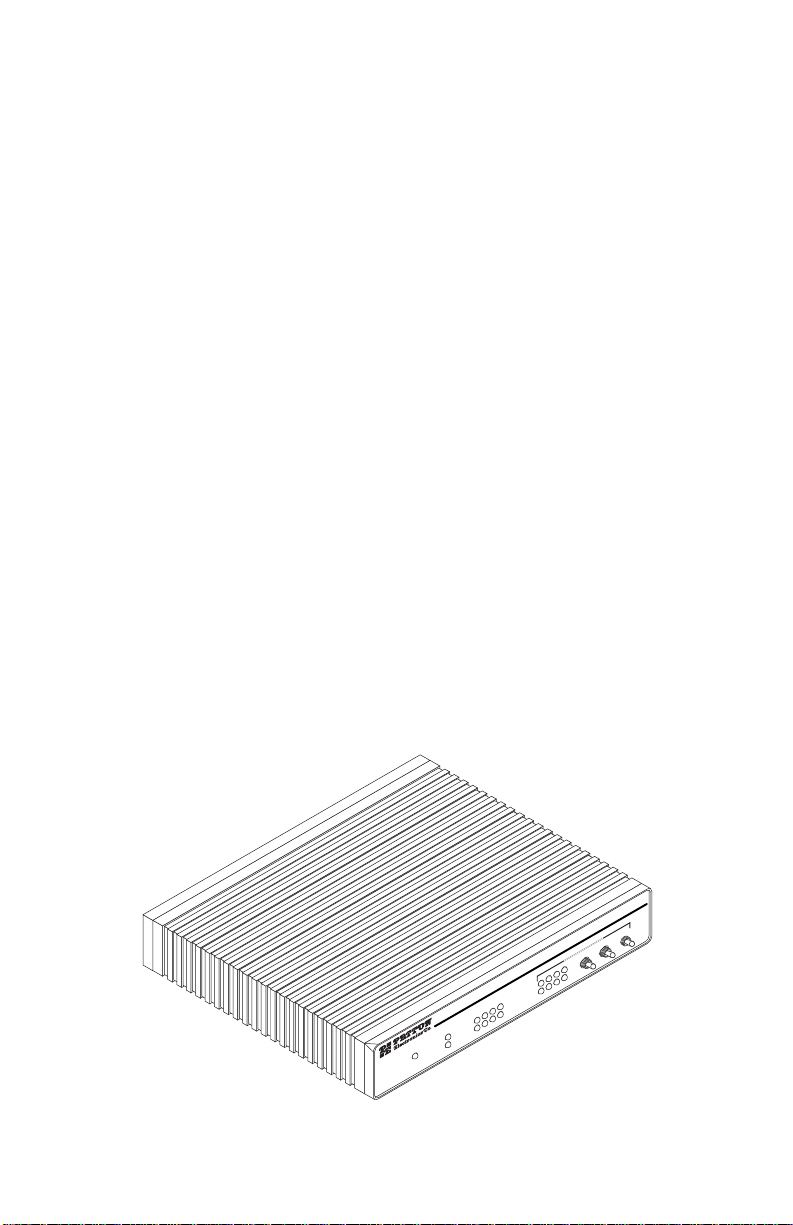
The Model 1194 (see Figure 1) enables service providers to offer cost
effective extension (see Figure 2 on page 9) and distribution of four T1/
E1 network circuits from a Telco’s Central Office to a point of presence
(POP), or in back-haul type operation linking CSU/DSUs, PABXs, routers, or multiplexers located at remote sites.
Figure 1.
b
i
F
k
n
i
L
S
r
N
e
w
o
P
Model 1194
8
m
e
d
o
M
4
0
.7
/G
3
0
.7
G
d
a
u
r - Q
e
1
1
ib
5
F
e
d
o
M
le
3
g
P
in
S
E
4
9
1
l 1
e
d
o
G.703/G.704 Test Modes
M
4
P
3
P
2
P
1
P
4
k
0
n
i
L
7
.
G
/
3
S
0
N
7
.
G
4
P
3
P
2
P
r
e
1
P
E
1
1
5
1
P
4
P
M
T
2
P
R
R
E
Page 9

Fiber Optic
Line
m
e
d
o
M
4
0
7
.
G
/
3
0
7
.
G
d
a
u
Q
r
1
e
1
b
i
5
F
e
d
o
M
e
l
3
g
P
n
i
E
S
1
E
1
4
5
9
1
1
1
l
P
e
d
o
4
G.703/G.704 Test Modes
M
P
M
T
2
P
R
R
E
4
P
3
P
2
P
1
P
k
in
L
.704
S
N
.703/G
G
4
P
3
P
2
P
1
iber
P
F
k
in
L
S
N
er
ow
P
m
e
d
o
M
4
0
7
.
G
/
3
0
7
.
G
d
a
u
Q
-
r
1
e
1
b
i
5
F
e
d
o
M
e
l
3
g
P
n
i
E
S
1
E
1
4
5
9
1
1
1
l
P
e
d
o
4
G.703/G.704 Test Modes
M
P
M
T
2
P
R
R
E
4
P
3
P
2
P
1
P
k
in
L
.704
S
N
.703/G
G
4
P
3
P
2
P
1
P
Fiber
k
in
L
S
r
N
e
ow
P
E1/T1E1/T1
Modem Modem
Figure 2.
Network extension between remote locations
Using a laser transmitter (1300nm) and a single-mode fiber (9/125 micro
meter), the Model 1194 offers a high speed, noise immune, full duple x fiber
link over a single strand of fiber with a reach of up to 15.5 miles (25.0 km).
The Model 1194 is available in two versions: 1194/T1 and 1194/E1, for
connection to T1 and E1 circuits respectively. Features include AMI,
B8ZS/HDB3 line coding; internal, network, and receiver recovered
clocks; all easily configured via DIP switches. Local/Remote loops and
V.52 compliant 511 test patterns are accessible via front panel switches,
allowing quick testing and troubleshooting of the Model 1194 transceivers, and fiber and network links.
The Model 1194 is equipped with 19 front panel LEDs that monitor
power, fiber, network, and diagnostic features status.
The single-mode fiber interface uses either an SC or FC fiber connector ,
while the network interfaces are presented on RJ-48C connectors.
The Model 1194 offers options for universal input (100–240 VAC) and
48 VDC power supplies
9
Page 10

3.0 CONFIGURATION
The Model 1194 has 16 DIP switches that enable configuration of the unit
for a wide variety of applications. This section describes location of the
switches and explains the different configurations.
3.1 CONFIGURING THE HARDWARE DIP SWITCHES
Using a small flat-tip screwdriver , remov e the protectiv e co v er located on
the underside of the Model 1194 (see Figure 3).
Power
Power
NS
NS
Link
Link
P4P3P2P1
P4P3P2P1
G.703/G.704Fiber
G.703/G.704Fiber
NS
NS
Link
Link
P4P3P2P1
P4P3P2P1
ERR
ERR
P
P
2
2
TM
TM
P
P
M
M
G.703/G.704 Test Modes
G.703/G.704 Test Modes
4
4
o
o
d
d
e
e
P
P
l
l
1
1
1
1
1
1
9
9
5
5
4
4
1
1
E
E
1
1
S
S
E
E
i
i
n
n
P
P
g
g
3
3
l
l
e
e
M
M
o
o
d
d
e
e
F
F
5
5
i
i
b
b
1
1
e
e
1
1
r
r
-
-
Q
Q
u
u
a
a
d
d
G
G
.
.
7
7
0
0
3
3
/
/
G
G
.
.
7
7
0
0
4
4
M
M
o
o
d
d
e
e
m
m
Figure 3.
Removing the cover to access DIP switches S1 and S2
Figure 4 shows the orientation of the DIP switches in the “ON” and “OFF”
positions.
S1
Switch toggle
ON
5678
1234
Push toggle up
for ON position
Push toggle
down for
OFF position
1234ON5678
1234ON5678
1234ON5678
S1
S2
1234ON5678
Figure 4.
DIP switches S1 and S2
10
S1
S2
Page 11

Configuring DIP switch S1
Switches S1-1 through S1-8 are used to configure clocking modes and
line coding. Default settings of the switches are shown in Table 1.
Descriptions of the switch options follow the table.
Table 1:
Switch S1 summary
Position
S1-1
S1-2
S1-3
Function Default Setting Selected Option
HDB3(E1)/B8ZS(T1) or
OFF HDB3(E1)/
AMI Line Coding
T1 Line Buildout
T1 Line Buildout
ON
ON
B8ZS(T1)
0 dB
S1-4 Reserved
S1-5 Reserved
S1-6 Clock Mode OFF Network
S1-7 ON
S1-8 Reserved
Switch S1-1: Line Coding Options.
Use switches S1-1 to determine
the line coding of the network interface ports. The setting should be
HDB3
if your unit is an1194/E1,
B8ZS
if your unit is an 1194/T1, or
(common to both T1 and E1 technologies) The line coding must be the
same line coding prescribed by the network access provider (NAP). Most
applications will use HDB3.
S1-1 Setting
ON AMI
OFF HDB3 (E1)/B8ZS(T1)
•
Alternate Mark Inversion (AMI
): AMI defines a pulse as a “mark,” a
binary one, as opposed to a zero. In an E1 Network connection, signals are transmitted as a sequence of ones and zeros. Ones are sent
as pulses, and zeros are sent as spaces, i.e., no pulse. Every other
pulse is inverted from the previous pulse in polarity, so that the signal
can be effectively transmitted. This means, however, that a long
sequence of zeros in the data stream will cause problems, since the
modem receiving the signal relies on the signal to recover the clock. If
you must use AMI, ensure that the data terminal equipment connected
to the unit provides a minimally acceptable pulse density. AMI coding
does not inherently account for ones density. To meet this requirement,
ensure that the data inherently meets pulse density.
AMI
•
High Density Bipolar 3 (HDB3
): In HDB3 coding, the transmitter
deliberately inserts a bipolar violation when excessive zeros in the
data stream are detected. The receiver recognizes these special viola-
11
Page 12

tions and decodes them as zeros. This method enables the network to
meet minimum pulse density requirements.
•
Bipolar 8 Zero Substitution (B8ZS
): This mode assures proper bit
density in the data stream. In this mode any data pattern can be transmitted without causing ones density errors. This mode allows for 64
kbps clear channel timeslots.
Switches S1-2 and S1-3: Line Build Out.
Line buildout (LBO) is a T1
equipment feature, it controls the transmitter signal strength and pulse
shape sent over the T1 line . For most applications, the def ault settings (0
dB) will suffice. When connecting to a carrier’s T1 circuit, the carrier will
determine what LBO is necessary. 0 dB provides the highest signal
strength, and therefore the longest distance, while -15.0 dB provides the
lowest usable signal le vel. -22.5 dB is used to test the line and should not
be used in normal applications.
Transmitted E1 signals are not specified in terms of LBO. Patton’s Model
1194/E1 complies with ITU-T G.703 recommendation for signal pulse
shape and amplitude, and has a reach of 1.6 km. No user configuration
is required
S1-2 S1-3 Function
ON ON 0dB
OFF ON -7.5dB
ON OFF -15.0dB
OFF OFF -22.5dB
Switches S1-6 and S1-7: Clock Mode.
Use switches S1-6 and S1-7 to
determine clock mode of the 1194.
S1-6 S1-7 Setting Description
ON ON Internal Transmit clock generated internally
ON OFF Receive
Recover
Transmit clock derived from the fiber
line link
OFF ON Network Transmit clock derived from E1 or T1
equipment interface
OFF OFF Internal use only
Note
The Model 1194 units are intended to work in pairs. Set the
clock modes for the Model 1194 units with one end of the link set
for receive recover and the other end set for either internal or
network.
12
Page 13

Configure DIP switch S2
Switches S2-1 through S2-8 are for configuring Local/Remote Loop, RDL
response, and front panel switch operation (see Tab le 2). Descriptions of
the switch options follow the table.
Table 2:
Switch S2 summary
Position
S2-1
Function Default Setting Selected Option
Local/Remote Loop OFF Local Loop
S2-2
S2-3
S2-4
Reserved
S2-5
S2-6
S2-7 Response to RDL OFF Enabled
S2-8 Front panel switches OFF Enabled
Switch S2-1: Local/Remote Loop.
Switch S2-1 determines which Loop
can be activated from the front panel loop switches (P1 to P4)
S2-1 Loop selected
OFF Local Loop
ON Remote Loop
Switch S2-7: Response to RDL.
Switch S2-7 enables or disables the
ability of the model 1194 to respond to RDL (Fiber Loop)
S2-7 RDL Response
ON Disabled (no response)
OFF Enabled
Switch S2-8: Front Panel Switches.
Switch S2-8 enables or disables
front panel switches, affecting the operation of P1 to P4 (loop switches)
and test pattern switches. In the ON position, S2-8 disables the operation
of front panel switches preventing the accidental activation of diagnostic
loops and test patterns.
S2-8 Front panel Switches
ON Disabled
OFF Enabled
13
Page 14

4.0 INSTALLATION
Once the Model 1194 is configured, it is ready to connect to the fiber
interface, to the E1/T1 equipment, and to the power source. This section
describes how to make these connections.
The power, network (E1/T1), and fiber line connections are located on
the rear panel of the Model 1194. Figure 5 sho ws the location of each of
these ports.
ON
P1 P2 P3 P4
OFF|O
Power
receptacle
Figure 5.
Network T1/E1
ports
Network, fiber, and power connection ports
FIBER
Fiber line
connector
4.1 CONNECT THE G.703/G.704 OR T1 NETWORK
The Model 1194 is equipped with 4 RJ-48C jacks for connection to an E1
or T1 network. Figure 6 shows the pinout for each of the four network
interface ports.
1 RX Data (TIP)
1
2
3
4
5
6
7
8
2 RX Data (RING)
3 (no connection)
4 TX Data (TIP)
5 TX Data (RING)
6 (no connection)
7 (no connection)
}
From Network
}
To Network
8 (no connection)
Figure 6.
E1 or T1 network interface
4.2 CONNECT THE FIBER INTERFACE
The Model 1194 is designed to be connected to another Model 1194.
The Model 1194 supports communication between T1 or E1 equipment
over single-mode fiber at distances up to 25 km (16 miles). One modem
can connect to another on the end of a single strand of fiber optic cable.
To connect two Model 1194s, use one strand of 9/125 micron singlemode fiber. The fiber connects to each Model 1194 using either an FC or
SC connector. Figure 7 shows a close-up of SC and FC connector types.
14
Page 15

Figure 7.
Single-mode fiber connectors (FC and SC)
.
Use of controls or adjustments or performance of
procedures other than those specified herein may result
in hazardous laser radiation exposure.
Caution
4.3 POWER CONNECTION
The Model 1194 is available with two power supply options:
•
Universal Interface AC Power Supply
option
(Model 1194-UI
) operates in environments ranging from 100 to 240 VAC, with no re-configuration necessary (see
Appendix B
for available domestic and
international power cords).
•
DC Power Supply
option
(Model 1194/48)
operates in 48 VDC (36–
60 VDC) environments and is equipped with a 3-pin “terminal strip”
style connector.
Connecting to an AC Power Source
The Universal Interface AC Supply is equipped with a male IEC-320
power connection. A domestic (US) power supply cord is supplied with
the unit at no extra charge. To connect the standard or universal power
supply, follow these steps:
1. Attach the power cord (supplied) to the shrouded male IEC-320 connector on the rear of the Model 1194.
2. Plug the power cord into a nearby AC power outlet.
15
Page 16

3. Set the ON/OFF power switch (see Figure 8) to ON.
ON/OFF power
switch
O
N
|
O
F
F
O
P
1
P
2
P
3
P
4
F
IB
E
R
Figure 8.
Power switch location
Connecting to a DC Power Source
The 48 VDC pow er supply option uses a 3-pin terminal bloc k with springtype connectors. Please refer to the
Model 1090 Series Service Manual
for the power line voltage connections.
There are no user-serviceable parts in the power supply
section of the Model 1194. Fuse replacement should only
be performed by qualified service personnel. Contact Patton Electronics Technical support at +1 (301) 975-1007,
via our web site at www.patton.com, or by E-mail at
support@patton.com, for more information.
WARNING
DC input power connector
ON
DC Input
+-E
OFF|O
P1 P2 P3 P4
O
N
|
D
C
I
n
+-E
p
u
t
O
F
F
O
P
1
P
2
P
3
FIBER
P
4
F
I
B
E
R
Figure 9.
DC power connection
16
Page 17

5.0 POWER-UP
To apply power to the Model 1194, first be sure that the unit is connected
to the appropriate power source. Then do the following:
1. Set front panel switches to the center position
2. Plug the provided AC or DC power into the Model 1194.
3. Set the ON/OFF power switch (see Figure 8 on page 16) to ON.
After the local and remote Model 1194s are powered up, a synchronization process will occur to establish a link. The synchronization
process should take approximately 5 seconds. If one of the Model
1194s loses power (for example, during a lightning storm), the local
and remote units will re-synchronize before they can resume data
transmission.
17
Page 18

6.0 LED STATUS MONITORS
The Model 1194 features front panel LEDs that monitor power, network,
fiber, and diagnostic signals. Figure 10 shows the front panel location of
each LED. Table 3 describes each LED’s function.
Model 1194E Single Mode Fiber - Quad G.703/G.704 Modem
Power
G.703/G.704Fiber
Link
NS
Link
NS
P4P3P2P1
G.703/G.704 Test Modes
TM
ERR
P4P3P2P1
511
P3P1
511EP4P2
Diagnostics LEDs
Power LED
Fiber LEDs
Figure 10.
Table 3:
Network LEDs
Front panel picture of 1194
Front panel LED descriptions
LED LED color Description
POWER Green Indicates the presence of AC or DC power
FIBER LINK Green Indicates the unit fiber link is synchronized
and operating correctly
FIBER NS Red Indicates the absence or synchronization
or fiber connection
Network Link (4) Green Indicates synchronization of the corre-
sponding E1 or T1 port (P1-P4)
Network Loss (4) Red Loss of synchronization or link of the cor-
responding E1 or T1 port (P1-P4)
Test Mode TM (4) Yellow Indicates the activation of Local, Remote,
or 511/511 pattern for corresponding E1
or T1 port (P1-P4)
Error ERR (4) Red Indicates the presence of errors in test
pattern data received
18
Page 19

7.0 TEST MODES
The following section describes the test patterns and loopbacks used in
the Model 1194. The Model 1194 offers local/remote loopback tests, plus
a built-in V.52 BER test pattern generator to evaluate the condition of the
modems and the network (T1/E1 lines) and fiber links. These tests can
be activated physically from the front panel. Before initiating a loopback
test, the user needs to select Local or Remote loops via DIP switch S2-1
located on the underside of the unit
S2-1 Loop Test Selected
OFF Local
ON Remote
7.1 LOCAL LOOPBACK TEST
This feature is used to test the T1 or E1 link on a per-port basis. Each of
the four T1 or E1 ports can be tested to verify the proper operation of the
line and the device at the remote end of the T1/E1 link. During local loopback the corresponding E1 or T1 port in the Model 1194 will transmit the
data received back to the originating device.
Set S2-1 to the OFF position, this setting prepares the Model 1194 for
local loop. The model 1194 has 3 front panel toggle switches, one of the
switches initiates 511/511E test patterns, the other two switches will initiate loops for a network port, the switches have labels corresponding to
network ports (P1 through P4). For example, to initiate a local loop on
network port 1, move the first switch from the left UP towards label “P1”.
See Figure 11 loop diagram
1
2
3
4
CSU/DSUs
E1/T1
Figure 11.
Fiber
1194 Local loop
19
E1/T1
1
2
11941194
3
4
CSU/DSUs
Page 20

To test the local connection, do the following:
1. Set S2-1 to the OFF position.
2. Locate the port label (P1-P4) above or below the front panel
switches, Activate local loopback for a network port by moving the
appropriate front panel toggle switch UP or DOWN. A yellow TM
LED corresponding to the port under test will turn on.
3. A BER (Bit Error Rate) test can be performed using a BER tester at the
far end of the T1/E1 link. If the BER test equipment indicates no faults
but the data indicates a fault, f ollo w the manufacturer's checkout procedures for the far end de vice. The BER test can also be perf ormed using
a built-in 511/511E pattern generator. (See the following section f or
more on how to use the built-in 511/511E pattern generator.)
4. Upon completion of the LAL test, return the front panel switch to center
position. After appro ximately 30 seconds , the TM LED should turn off.
7.2 REMOTE LOOPBACK TEST
The Remote loopback feature tests the perf ormance of the local and remote
1194 and the fiber optic link. During this test, data transmitted from a T1 or
E1 port at a local 1194 and sent over the fiber link is returned by the remote
1194. F or example , to initiate a remote loop test on network port 1, move the
first switch from the left UP towards label “P1”, data sent from port 1 will go
through the 1194 and fiber link to the remote 1194 (see Figure 12). The
remote 1194 will send port 1 data back to the originating device, as well as
to the corresponding port on it’s E1/T1 network side.
In order to prepare the Model 1194, make sure that fiber connection is in
place. V erify that the “Fiber link” LED on the front panel of the 1194 is ON.
E1/T1
1
2
Fiber
3
E1/T1
1
2
3
11941194
4
CSU/DSUs
Figure 12.
1194 Remote Loop
4
CSU/DSUs
20
Page 21

To test the fiber connection, do the following:
1. Set S2-1 to the ON position.
2. Locate the port label (P1-P4) above or below the front panel
switches, Activate Remote Loopback for a network port by moving
the appropriate front panel toggle switch UP or DOWN. A green TM
LED corresponding to the port under test will turn on. A BER test
can now be initiated using a BER tester or the built-in 511/511E pattern generator.
3. Upon completion of the remote loop test, return the front panel
switch to center position. After appro ximately 30 seconds, the TM LED
should turn off.
7.3 THE V.52 TEST PATTERN GENERATOR
To use the V.52 BER test in conjunction with the Local or Remote Loopbacks, follow these instructions:
1. Locate the “511/511E” toggle switch on the front panel of the Model
1194 and move it UP. This activates the V.52 BER test mode and
transmits a “511” test pattern into the loop . If any errors are present,
the red “ERR” LED corresponding to the port under test will blink
intermittently.
2. If the above test indicates no errors, move the V.52 toggle switch
down, activating the “511/E” test with errors present. If the test is
working properly, the local 1194 red “ERR” LED will blink approximately once every 2 seconds. A successful “511/E” test will confirm
that the link is in place, and that the Model 1194’s built-in “511” generator and detector are working properly.
Note
Note: When the unit is set for Network Clock Mode, the unit will
derive its timing from the Network (T1/E1)Interface. Failure to
connect to the network may result in bit errors during the 511 or
511/E test.
21
Page 22

APPENDIX A
MODEL 1194 QUAD E1/T1 TO SINGLE MODE FIBER SPECIFICATIONS
A.1 CONFIGURATION
Externally accessible dip switches
A.2 CLOCKING MODES
Network (E1/T1), Internal, Receive Recover (fiber Link)
A.3 NETWORK PORTS SPECIFICATIONS
Network Line Rate
2048 kbps (G.703), 1.544Mbps (T1)
Transmit Line Buildout (T1)
0 dB, -7.5 db, -15 db, and -22.5 dB
Interface
RJ-48C 120 ohm (E1), 100 ohm (T1)
Line coding
AMI or HDB3 (E1), B8ZS (T1)
Isolation
1500 Vrms
Physical Connection
• (RJ-48C)
• pin 1 Rx Data Tip
• pin 2 Rx Data Ring
• pin 4 Tx Data Tip
• pin 5 Tx Data Ring
• pins 3, 6, 7, 8 no connection
22
Page 23

A.4 FIBER PORT SPECIFICATIONS
Fiber Line Coding
8B10B
Fiber Physical
• Connection: One str and of 9/125 micron single-mode fiber with FC or
SC connectors
• Transmission Line: Single fiber
• Link Budget: 13 dB
A.5 DIAGNOSTICS
V.52 compliant (511/511E) pattern generator and detector with error
injection mode. Remote Loopback (toward fiber line) and local loopback
(toward T1/E1 Network) controlled by front panel switches
A.6 COMPLIANCE
FCC Part 15, FCC Part 68, CE, CTR12.
UL1950, CAN/CSA C22.2 No. 950
A.7 LASER SAFETY
Complies with 21CFR 1010 and 1040, Class 1 Lasers
A.8 NETWORK LINE INTERFACE
Transformer coupled, 1500 VAC isolation
A.9 POWER
• 100–240 VAC, 400 mA, 50–60 Hz (universal input);
• 48 VDC (option). (36–60) 340 mA input.
A.10 TEMPERATURE RANGE
32–122°F (0–50°C)
A.11 ALTITUDE
0–15,000 feet
23
Page 24

A.12 HUMIDITY
5 to 95%, non-condensing
A.13 DIMENSIONS
7.3 W x 6.6 D x 1.62H in. (185 W x 168 D x 41 H mm)
A.14 WEIGHT
2.01 lbs. (1.0kg)
A.15 MEAN TIME BETWEEN FAILURE (MTBF)
113,258 hours, based on MIL-HDBK-217F, Notice 2.
24
 Loading...