

Page 1
USER
MANUAL
MODEL 1140A
Miniature Fiber Optic
Modem w/V.54
Diagnostics
SALES OFFICE
(301) 975-1000
TECHNICAL SUPPORT
(301) 975-1007
http://www.patton.com
Part# 07M1140A-A
Doc# 018061UA
Revised 10/04/99
An ISO-9001
Certified Company
Page 2

1 2
11..00 WWAARRRRAANNTTYY IINNFFOORRMMAATTIIOONN
Patton Electronics warrants all Model 1140A components to be
free from defects, and will—at our option—repair or replace the product
should it fail within one year from the first date of shipment.
This warranty is limited to defects in workmanship or materials,
and does not cover customer damage, abuse or unauthorized modification. If this product fails or does not perform as warranted, your sole
recourse shall be repair or replacement as described above. Under no
condition shall Patton Electronics be liable for any damages incurred
by the use of this product. These damages include, but are not limited
to, the following: lost profits, lost savings and incidental or consequential damages arising from the use of or inability to use this product.
Patton Electronics specifically disclaims all other warranties,
expressed or implied, and the installation or use of this product shall be
deemed an acceptance of these terms by the user.
1.1 RADIO AND TV INTERFERENCE
The Model 1140A generates and uses radio frequency energy,
and if not installed and used properly—that is, in strict accordance with
the manufacturer's instructions—may cause interference to radio and
television reception. The Model 1140A has been tested and found to
comply with the limits for a Class A computing device in accordance
with the specifications in Subpart J of Part 15 of FCC rules, which are
designed to provide reasonable protection from such interference in a
commercial installation. However, there is no guarantee that interference will not occur in a particular installation. If the Model 1140A does
cause interference to radio or television reception, which can be determined by disconnecting the RS-232 interface, the user is encouraged
to try to correct the interference by one or more of the following measures: moving the computing equipment away from the receiver, re-orienting the receiving antenna and/or plugging the receiving equipment
into a different AC outlet (such that the computing equipment and
receiver are on different branches).
1.2 SERVICE
All warranty and non-warranty repairs must be returned freight prepaid and insured to Patton Electronics. All returns must have a Return
Materials Authorization number on the outside of the shipping container. This number may be obtained from Patton Electronics Technical
Service at (301) 975-1007.
Packages received without an RMA num-
ber will not be accepted.
Patton Electronics' technical staff is also available to answer any
questions that might arise concerning the installation or use of your
Model 1140A. Technical Service hours: 8AM to 5PM EST, Monday
through Friday.
22..00 GGEENNEERRAALL IINNFFOORRMMAATTIIOONN
Thank you for your purchase of this Patton Electronics product.
This product has been thoroughly inspected and tested and is warranted for One Year parts and labor. If any questions or problems arise
during installation or use of this product, please do not hesitate to contact Patton Electronics Technical Support at (301) 975-1007.
2.1 FEATURES
• Supports async. or sync. communication over dual optical fibers
• V.52 and V.54 diagnostics
• Data rates to 57.6 Kbps
• Range to 3.5 miles
• Immune to RFI/EMI noise, ground loops and transient surges
• Easily accessible Diagnostic & Configuration Switches
• Switch-selectable carrier control
• Requires no AC power or batteries
• Two easy-to-read status indicators
• Male or female DB-25 and SMA or ST connectors available
2.2 DESCRIPTION
The Patton Model 1140A miniature dual fiber optic modem brings
fiber to the desktop. Combining the inviolability of fiber with the troubleshooting capabilities of V.52 and V.54 diagnostics, the Model 1140A
is the best choice for your most critical RS-232 links. The Model
1140A operates async. or sync., supports data rates to 57.6 Kbps and
plugs directly into a workstation’s RS-232 port.
Like all fiber optic modems, the Model 1140A is inherently immune
to RFI/EMI noise, ground loops and transient surges. The carrier may
be switch selected as either “Continuously On”or “Controlled by RTS”,
while an easily accessible DCE/DTE switch eliminates the need for
cumbersome RS-232 crossover cables. Two easy-to-read LED indicators monitor the Error and Test modes. Drawing all necessary power
from the RS-232 interface, the Model 1140A requires no AC power or
batteries to operate.
Measuring only 3.42” x 2.10” x .73”, the Model 1140A is able to fit
into tight installation spaces. On the RS-232 side, the Model 1140A
comes equipped with either a male or female DB-25 connector; on the
fiber side, it is available with a choice of SMA or ST connectors.
Page 3
3 4
3.0 CONFIGURATION
The Model 1140A is simple to install and is ruggedly designed for
excellent reliability: just set it and forget it. The following instructions
will help you set up and install the Model 1140A properly. If you have
any questions, don't hesitate to call Patton's Technical Support Hotline
at (301) 975-1007 (9-5 PM, EST).
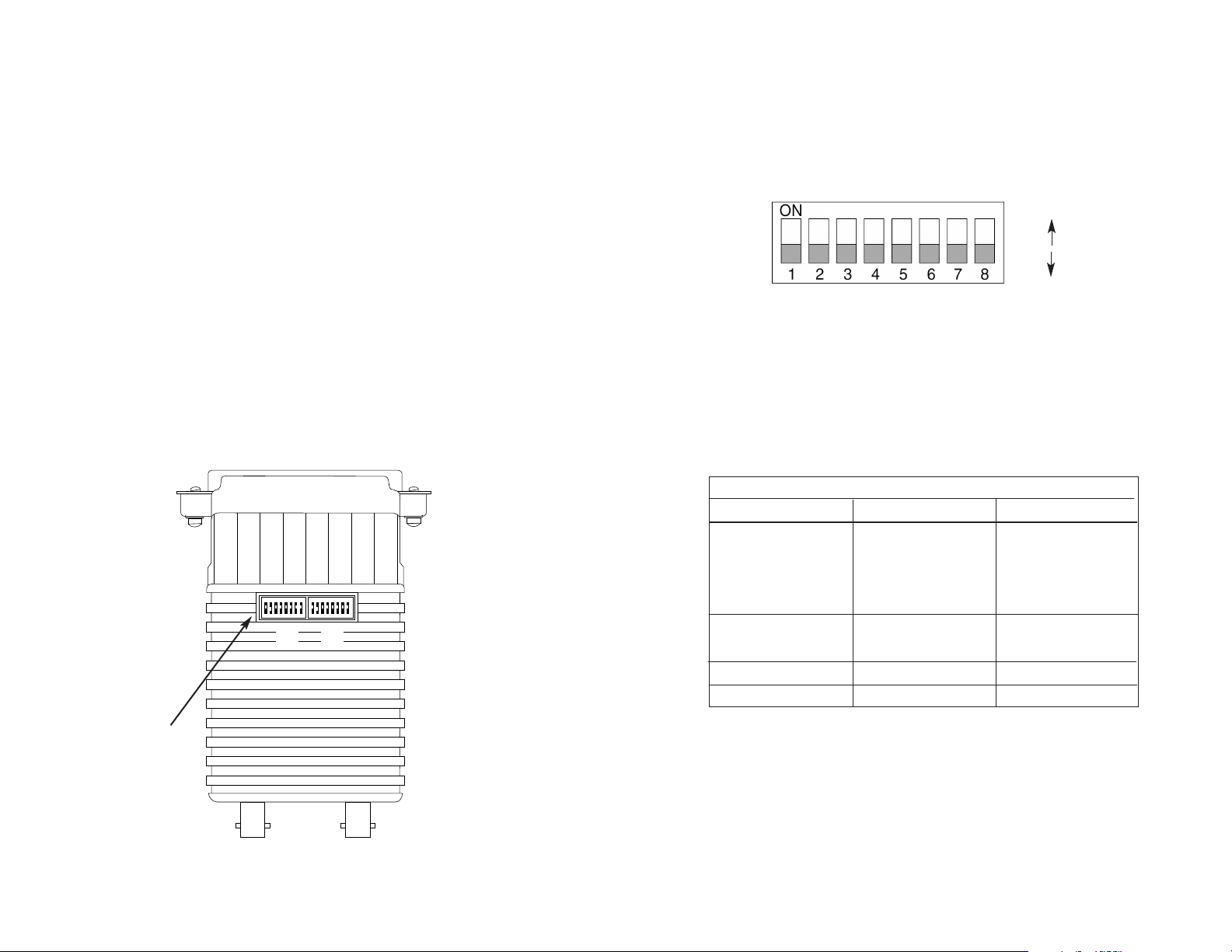
3.1 CONFIGURATION SWITCHES
The Model 1140A uses a unique set of 16 external mini DIP
switches that allow configuration to an extremely wide range of applications. These 16 DIP switches are grouped in two eight-switch sets, and
are externally accessible from the underside of the Model 1140A (see
Figure 1). Since all configuration DIP switches are externally accessible,
there is no need to open the Model 1140A's case for configu-
ration.
The configuration switches allow you to select data rates, clocking
methods, V.52 & V.54 tests, word lengths, extended signaling rates,
async. or sync. mode. The drawings, text and tables on the following
pages describe all switch locations, positions and functions.
The Model 1140A has two sets of eight switches, yielding 16 total
DIP switches. The two sets will be referred to as S1 and S2. As
Figure 2 shows, the orientation of all DIP switches is the same with
respect to “ON” and “OFF” positions.
3.2 CONFIGURATION SWITCH SET “S1”
The DIP switches on S1 set data rate, clock source, async./sync.
mode and carrier control method. The default settings are summarized
in the table below.
Figure 1. Model 1140A Configuration Switches External Position
Figure 2. Close-up of DIP switches showing “ON”and “OFF” positions
OFF
ON
S1 SUMMARY TABLE
Position Function Factory Default
S1-1 Data Rate On
S1-2 Data Rate Off
S1-3 Data Rate Off
S1-4 Data Rate On
S1-5 Clock Source On
S1-6 Clock Source On
S1-7 Async./Sync. On Async.
S1-8 Carrier Control Off Constantly On
9,600 bps
Internal
}
}
Figure 3. Summary of DIP switch default settings for set S1
S1 S2
Configuration
Switches
12345678
OFF
12345678
OFF
Page 4

5 6
S1-1 through S1-4: Data Rate Setting
Switches S1-1 through S1-4 are set in combination to determine
the asynchronous and synchronous data rate for the Model 1140A.
S1-1 S1-2 S1-3 S1-4 Setting
On On On On 1.2 Kbps
Off On On On 1.8 Kbps
On Off On On 2.4 Kbps
Off Off On On 3.6 Kbps
On On Off On 4.8 Kbps
Off On Off On 7.2 Kbps
On Off Off On 9.6 Kbps
Off Off Off On 14.4 Kbps
On On On Off 19.2 Kbps
Off On On Off 28.8 Kbps
On On Off Off 38.4 Kbps
Off On Off Off 57.6 Kbps
S1-5 and S1-6: Clock Source
Switches S1-5 and S1-6 are set in combination to determine the
transmit clock source for the Model 1140A.
S1-5
S1-6 Setting
On On Inter nal transmit clock
Off On Receive recover clock
On Off Exter nal transmit clock
S1-7: Asynchronous/Synchronous Mode
The setting for switch S1-7 determines whether the Model 1140A
is in asynchronous or synchronous operating mode.
S1-7 Setting
On Asynchronous
Off Synchronous
S1-8: Carrier Control Method
The setting for switch S1-8 determines whether the carrier is “constantly on” or “controlled by RTS”. This setting allows for operation in
switched carrier, multipoint and/or hardware handshaking applications.
S1-8 Setting
Off Constantly On
On Switched Carrier
3.3 CONFIGURATION SWITCH SET “S2”
The DIP switches on S2 set word length, extended signaling rate,
RTS/CTS delay and V.52 and V.54 diagnostic test.
S2-1 and S2-2: Word Length
Switches S2-1 and S2-2 are set in combination to determine the
word length for asynchronous data, including start and stop bits.
S2-1
S2-2 Setting
Off On 8 bits
On On 9 bits
Off Off 10 bits
On Off 11 bits
S2 SUMMARY TABLE
Position Function Factory Default
S2-1 Word Length Off
S2-2 Word Length Off
S2-3
Extended Signaling Rate
Off -2.5% to +2.3%
S2-4 RTS/CTS Delay On
S2-5 RTS/CTS Delay On
S2-6 Future Use S2-7 Future Use S2-8 V.52/V.54 Tests Off
Enable
Figure 4. Summary of DIP switch default settings for S2
}
}
7 mS
10 bits
Page 5

7 8
S2-3: Extended Signaling Rate
The setting for switch S2-3 determines the range of variability the
Model 1140A “looks for”in asynchronous data rates (i.e., the actual
variance from a given frequency level the Model 1140A will tolerate).
S2-3 Setting
Off -2.5% to +1% Basic
On -2.5% to +2.3% Extended
S2-4 and S2-5: RTS/CTS Delay
The combined settings for switches S2-4 and S2-5 determine the
amount of delay between the time the Model 1140A “sees”RTS and
when it sends CTS. Options are no delay, 7 ms and 53 ms.
S2-4
S2-5 Setting
On On 7 mS
Off On 53 mS
On Off No delay
Off Off No delay
S2-8: V.54 Loopback Test Enable
To reset the V.54 circuit, set switch S2-6 to the “ON” position, then
back to the “OFF” position..
S2-8 Setting
Off V.54 Enable
On V.54 Disable
4.0 INSTALLATION
The Model 1140A is easy to install. After configuring the DIP
switches, simply connect the two fiber cables and then connect the
RS-232 interface. Figure 5 shows the location of the fiber connections
on the Model 1140A’s rear panel.
4.1 FIBER CONNECTIONS
The Model 1140A short range modems are designed to work in
pairs
. You will need one at each end of a dual fiber cable. This cable
connects to each Model 1140A using either an ST or an SMA connector. Figure 6 shows a close up of each of these connector types.
4.2 RS-232 CONNECTION
The Model 1140A is designed to remain in DCE mode.
Figure 6. Close up of ST and SMA connections
Figure 5 Close up of ST and SMA connections
ST
SMA
Alignment pin
faces down
DIP Switches This Side
TX RX
Page 6

9 10
5.0 OPERATION
Once you have configured each Model 1140A properly and connected the fiber and RS-232 cables, you are ready to operate the units
This section describes the LED status monitors, the V.52 and V.54
diagnostics and the power up process.
5.2 TEST MODES
The Model 1140A offers two V.54 test modes to evaluate the condition of the modems and the communication link. These tests can be
activated physically from the front panel, or via the interface. Note:
V.54 test modes on the Model 1140A are available for point-to-point
applications only.
5.2.1 LOCAL ANALOG LOOPBACK (LAL)
The Local Analog Loopback (LAL) test checks the operation of the
local Model 1140A, and is performed separately on each unit. Any
data sent to the local Model 1140A in this test mode will be echoed
(returned) back to the user device. For example, characters typed on
the keyboard of a terminal will appear on the terminal screen. To perform a LAL test, follow these steps:
A. Activate LAL. This may be done in one of two ways: First, by
moving the front panel toggle switch DOWN to “LAL”. Second, by raising pin 18 on the interface. (Note: Make sure DIP switch SW2-8 is
OFF). Once LAL is activated, the Model 1140A transmit output is connected to its own receiver. The “test” LED should be lit.
B. Verify that the data terminal equipment is operating properly
and can be used for a test. If a fault is indicated, call a technician or
replace the unit.
C. Perform a BER (bit error rate) test on each unit. If the BER test
equipment indicates no faults, but the data terminal indicates a fault,
follow the manufacturer’s checkout procedures for the data terminal.
Also, check the interface cable between the terminal and the Model
1140A.
5.2.2 REMOTE DIGITAL LOOPBACK (RDL)
The Remote Digital Loopback (RDL) test checks the performance
of both the local and remote Model 1140As, and the communication
link between them. Any characters sent to the remote Model 1140A in
this test mode will be returned back to the originating device. For
example, characters typed on the keyboard of the local terminal will
appear on the local terminal screen after having been passed to the
remote Model 1140A and looped back. To perform an RDL test, follow
these steps:
A. Activate RDL. This may be done in two ways: first, by moving
the front panel toggle switch UP to “RDL”. Second, by raising pin 21 on
the interface. (Note: Make sure SW2-8 is OFF).
B. Perform a BER (bit error rate) test on the system.
C. If the BER test indicates a fault, and the Local Analog
Loopback test was successful for both Model 1140As, you may have a
problem with the fiber line between the modems. You should then
check the fiber line for proper connections and continuity.
NOTE: The Model 1140A optical power output was increased.
Therefore, Model 1140A is not compatible with Model 1140.
Error LED
Test LED
Page 7

11 12
5.2.3 USING THE V.52 BER TEST INDEPENDENTLY
The V.52 BER test can be used independently of the V.54 loopback tests. This requires two operators: one to initiate and monitor the
test at the local Model 1140A, and one at the remote Model 1140A. To
use the V.52 BER test by itself, both operators should simultaneously
follow these steps:
1. Locate the “511/511E” toggle switch on the front panel of the
1140A and move it DOWN. This activates the V.52 BER test mode and
transmits a “511” test pattern to the other unit. If any errors are present, the receiving modem’s red “Error” LED will blink sporadically.
Note: For this test to function, the “511” switch on both Model 1140As
must be on.
2. If the test indicates no errors are present, move the V.52 toggle
switch UP, activating the “511/E” test with errors present. If the test is
working properly, the receiving modem's red “Error” LED will glow. A
successful “511/E” test will confirm that the link is in place, and that the
Model 1140A’s built-in “511” generator and detector are working properly.
5.3 POWER UP
Once the Model 1140A is properly installed, it should operate
transparently—as if it were a standard cable connection. Since operating power is derived from the RS-232 data and control signals; there is
no “ON/OFF” switch. All data signals from the RS-232 interface are
passed straight through.
APPENDIX A
PATTON ELECTRONICS MODEL 1140A
SPECIFICATIONS
Transmission Line: Dual optical cable
Transmission Mode: Async. or sync., half or full duplex
Interfaces: EIA RS-232, CCITT V.24
Data Rates: 0 - 57.6Kbps
Distance: 3.5 miles over continuous fiber
RTS/CTS Delay: Switch-selectable: No delay, 9.0 mS,
79.5 mS
Receiver Sensitivity: -38 dBm
Coupled Power Output: > -25dBm
Optic Wavelength: 850 nm
LED Indicators: Carrier Detect and Fiber Optic Output
Connectors: DB-25 male or female on RS-232 side; ST
or SMA connectors on fiber side
Power Supply: No external power required; uses power
from RS-232 data and control signals
Temperature Range: 0-60°C (32-140°F)
Altitude: 0-15,000 feet
Humidity: Up to 95% non-condensing
Weight: 2 oz.
Dimensions: 23.42” x 2.10” x 0.73”
Page 8

13 14
APPENDIX B
PATTON ELECTRONICS MODEL 1140A
RS-232 PIN CONFIGURATIONS
APPENDIX C
PATTON ELECTRONICS MODEL 1140A
BLOCK DIAGRAM
Copyright © 1998
Patton Electronics Company
All Rights Reserved
1- (FG) Frame Ground
2- (TD) Transmit Data To Model 1140A
3- (RD) Receive Data From Model 1140A
4- (RTS) Request to Send To Model 1140A
5- (CTS) Clear to Send From Model 1140A
6- (DSR) Data Set Ready From Model 1140A
7- (SG) Signal Ground
8- (DCD) Data Carrier Detect From Model 1140A
To Model 1140A Data Term. Ready (DTR) - 20
To Model 1140A Remote Loop (RL) - 21
From Model 1140A Transmit Clock (TC) -15
From Model 1140A Receiver Clock (RC) - 17
To Model 1140A Local Loop (LL) - 18
DIRECTION “DCE” STANDARD SETTING DIRECTION
MODEL 1140A
BLOCK DIAGRAM
 Loading...