

Page 1
USER
MANUAL
MODEL 1110A
Asynchronous, Carrier
Controlled Fiber Optic
Modem
CERTIFIED
An ISO-9001
Certified Company
Part# 07M1110A-B
Doc# 018051UB
Revised 7/18/97
SALES OFFICE
(301) 975-1000
TECHNICAL SUPPORT
(301) 975-1007
http://www.patton.com
Page 2

1.0 WARRANTY INFORMATION
Patton Electronics warrants all Model 1110A components to be
free from defects, and will—at our option—repair or replace the product
should it fail within one year from the first date of shipment.
This warranty is limited to defects in workmanship or materials, and
does not cover customer damage, abuse or unauthorized modification.
If this product fails or does not perform as warranted, your sole
recourse shall be repair or replacement as described above. Under no
condition shall Patton Electronics be liable for any damages incurred
by the use of this product. These damages include, but are not limited
to, the following: lost profits, lost savings and incidental or
consequential damages arising from the use of or inability to use this
product. Patton Electronics specifically disclaims all other warranties,
expressed or implied, and the installation or use of this product shall be
deemed an acceptance of these terms by the user.
1.1 RADIO AND TV INTERFERENCE
The Model 1110A generates and uses radio frequency energy, and
if not installed and used properly—that is, in strict accordance with the
manufacturer’s instructions—may cause interference to radio and
television reception. The Model 1110A has been tested and found to
comply with the limits for a Class A computing device in accordance
with the specifications in Subpart J of Part 15 of FCC rules, which are
designed to provide reasonable protection from such interference in a
commercial installation. However, there is no guarantee that
interference will not occur in a particular installation. If the Model 1110A
does cause interference to radio or television reception, which can be
determined by disconnecting the RS-232 interface, the user is
encouraged to try to correct the interference by one or more of the
following measures: moving the computing equipment away from the
receiver, re-orienting the receiving antenna and/or plugging the
receiving equipment into a different AC outlet (such that the computing
equipment and receiver are on different branches).
1.3 SERVICE
All warranty and non-warranty repairs must be returned freight
prepaid and insured to Patton Electronics. All returns must have a
Return Materials Authorization number on the outside of the shipping
container. This number may be obtained from Patton Electronics
Technical Service at (301) 975-1007, at our web site at
http://www.patton.com, or at support@patton.com.
Packages
received without an RMA number will not be accepted.
Patton Electronics’ technical staff is also available to answer any
questions that might arise concerning the installation or use of your
Model 1110A. Technical Service hours: 8AM to 5PM EST, Monday
through Friday.
1.2 CE NOTICE
The CE symbol on your Patton Electronics equipment indicates
that it is in compliance with the Electromagnetic Compatibility (EMC)
directive and the Low Voltage Directive (LVD) of the Union European
(EU). A Certificate of Compliance is available by contacting Technical
Support.
1
2
Page 3
2.0 GENERAL INFORMATION
3.0 CONFIGURATION
Thank you for your purchase of this Patton Electronics product.
This product has been thoroughly inspected and tested and is
warranted for One Year parts and labor. If any questions or problems
arise during installation or use of this product, please do not hesitate to
contact Patton Electronics Technical Support at (301) 975-1007.
2.1 FEATURES
• Communicates over dual optical fibers
• Data rates to 19.2 Kbps
• Distances to 4 miles (6.44 km)
• Plugs directly into an RS-232 port
• Immune to RFI/EMI noise, ground loops and transient surges
• Easily accessible DCE/DTE switch
• DIP Switch-selectable carrier control
• Requires no AC power or batteries
• Two easy-to-read status indicators
• Fits into tight installation spaces
• Male or female DB-25 and SMA or ST connectors available
2.2 DESCRIPTION
The Patton Model 1110A miniature RS-232 fiber optic modem
brings fiber to the desktop. Communicating over dual optical fibers, the
Model 1110A supports data rates to 19.2 Kbps and distances to 4 miles
(6.44 km). The Model 1110A operates full or half duplex and plugs
directly into a workstation’s RS-232 port.
Like all fiber optic modems, the Model 1110A is inherently immune
to RFI/EMI noise, ground loops and transient surges. The carrier may
be switch selected as either “Continuously On” or “Controlled by RTS”,
while an easily accessible DCE/DTE switch eliminates the need for
cumbersome RS-232 crossover cables. Two easy-to-read LED
indicators monitor the status of carrier detect and fiber optic output.
Drawing all necessary power from the RS-232 interface, the Model
1110A requires no AC power or batteries to operate.
Measuring only 2.66” x 2.10” x .73”, the Model 1110A is able to fit
into tight installation spaces. A convenient pop-open/snap-shut ABS
plastic case allows easy access to configuration switches. On the
RS-232 side, the Model 1110A comes equipped with either a male or
female DB-25 connector; on the fiber side, it is available with a choice
of SMA or ST connectors.
The Model 1110A is simple to install and is ruggedly designed for
excellent reliability. This section describes how to configure the Model
1110A’s DCE/DTE switch and how to set the internal DIP switches.
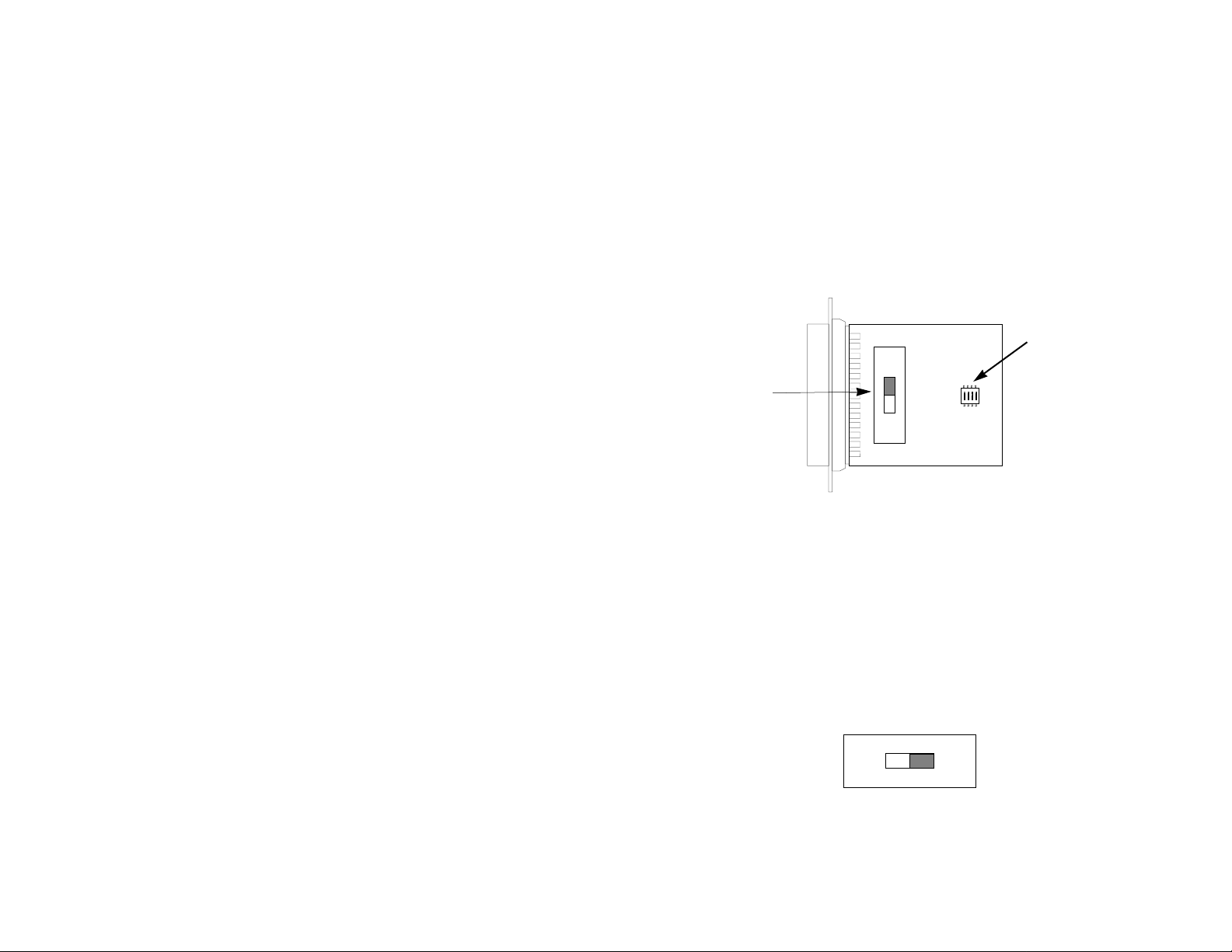
3.1 CONFIGURATION SWITCHES
The Model 1110A uses a DTE/DCE switch and a 4 position internal
DIP switch that allow configuration to wide range of applications.
Figure 1, below, shows the position of the DIP switch and the DCE/DTE
switch on the top of the Model 1110A PC board.
DIP Switches
DCE/DTE
Switch
Figure 1. Model 1110A PC board, showing switch and strap locations
DTE
DCE
1234
ON
3.1 SETTING THE EXTERNAL DCE/DTE SWITCH
For your convenience, the Model 1110A has an externally
accessible DCE/DTE switch (see Figure 2, below). If the device
connected to the Model 1110A is a PC, terminal (or is wired like one),
set the switch to “DCE” (Default Setting). This causes the Model 1110A
to behave like Data Communications Equipment and transmit data on
pin 3. If the device connected to the Model 1110A is a modem or
multiplexer (or is wired like one), set the switch to “DTE”. This causes
the Model 1110A to behave like Data Terminal Equipment and transmit
data on pin 2.
DCE
DCE DTE
Figure 2 Externally accessible DCE/DTE switch
Default Setting = “DCE”
DTE
3 4
Page 4

3.2 SETTING INTERNAL DIP SWITCHES
3.2.2 Configuration Switch Set “S1”
The Model 1110A uses four internal DIP switches that allow
configuration for a wide range of applications. In order to set the
internal DIP switches, you must open the Model 1110A case.
NOTE: Before opening the case, determine whether the default
settings are correct for your application (see Section 3.2.2).
3.2.1 Opening the Case
To open the Model 1110A case, insert a flat head screw driver
between the case lip and DB-25 connector (see Figure 3).
Figure 3. Using a small screwdriver to separate the Model 1110A case
Twist the screw driver head slightly and the top half of the case will
separate from the lower half, as in Figure 4, below.
The switches on DIP switch S1 are used to set the RTS/CTS delay
and the method of carrier control. Figure 5 shows the orientation of the
switches on DIP Switch S1 with respect to ON/OFF positions.
ON
OFF
Figure 5. Close-up of DIP Switches Showing “ON” and “OFF” Positions
1234
ON
The default settings for DIP switch S1 are shown in the table below.
Detailed descriptions of each switch follow the table.
S1 SUMMARY TABLE
Position Function Factory Default
S1-1 RTS/CTS Delay On
S1-2 RTS/CTS Delay On
9.5 mS
}
S1-3 Carrier Control Off Constant
S1-4
Factory Use Only
* Indicates Mandatory Setting
Off*
Figure 4. Using a small screwdriver to separate the Model 1110A case
To set the switches, use a small screwdriver and gently push each
switch to its proper setting. Finally, fit the case halves together and
push to snap closed.
5 6
Switches S1-1 & S1-2: RTS/CTS Delay
The combined settings for switches S1-1 and S1-2 determine the
amount of delay between the time the Model 1110A “sees” RTS and
then sends CTS to the DTE device. Options are no delay, 9.5 ms and
79.5 ms.
S1-1
S1-2 Setting
Off Off No delay
On On 9.5 ms
On Off 79.5 mS
On Off Not a Valid Setting
Page 5

Switch S1-3: Carrier Control Method
The setting for switch S1-3 determines whether the carrier is
“constantly on” or “controlled by RTS”. This setting allows for operation
in switched carrier or hardware handshaking applications.
S1-3 Setting
Off Constantly on
On Controlled by RTS
Switch S1-4: Factory Use Only
4.0 INSTALLATION
The Model 1110A is easy to install. After configuring the DIP
switches, simply connect the two fiber cables and then connect the
RS-232 interface. Figure 6 (below) shows the location of the fiber
connections on the Model 1110A’s rear panel.
This switch is
reserved for factory use
OFF position.
S1-4 Setting
Off Normal Operation
On Not a Valid Setting
and must remain in the
Figure 6. Rear panel of the Model 1110A, showing fiber connections
4.1 FIBER CONNECTIONS
The Model 1110A short range modems are designed to work in
pairs
. You will need one at each end of a dual fiber cable. This cable
connects to each Model 1110A using either an ST or an SMA
connector. Figure 7 (below) shows a close up of each of these
connector types.
SMA
ST
Alignment pin
Figure 7. Close up of ST and SMA connections
faces down
7 8
Page 6

4.2 RS-232 CONNECTION
Because the Model 1110A is designed to behave as either a DCE
or a DTE device, it does not need special cables to operate. Always
use a
straight-through
RS-232 cable.
5.0 OPERATION
Once you have configured each Model 1110A properly and
connected the fiber and RS-232 cables, you are ready to operate the
units. This section describes the LED status monitors and the power
up process.
Notice! Any terminal cable connected to the Model
1110A must be shielded cable, and the outer shield must
be 360 degree bonded–at both ends–to a metal or
metalized backshell.
5.1 LED STATUS MONITORS
The Model 1110A features two status LEDs that indicate the
condition of carrier detect and fiber optic output. Figure 8 (below)
shows the back panel location of each LED. Following Figure 8 is a
description of each LED’s function.
Carrier Detect Fiber Optic Output
LEDs
Transmit FiberReceive Fiber
Figure 8. Back panel view of the Model 1110
• The “Carrier Detect” LED will glow red when a proper carrier
frequency is recognized.
• The “Fiber Optic Output” LED will glow red to indicate
presence of infrared output and transmit carrier
5.2 POWER UP
Once the Model 1110A is properly installed, it should operate
transparently—as if it were a standard cable connection. Since
operating power is derived from the RS-232 data and control signals;
there is no “ON/OFF” switch. All data signals from the RS-232
interface are passed straight through.
When the local and remote Model 1110A’s are both powered up
and passing data normally, the following LED conditions will exist:
• Carrier detect = solid red
• Fiber optic output = solid red
9 10
Page 7

APPENDIX A
APPENDIX B
PATTON MODEL 1110A SPECIFICATIONS
Transmission Line: Dual optical cable
Transmission Mode: Asynchronous, half or full duplex, point-to-
point
Interfaces: EIA RS-232, CCITT V.24
Data Rates: 0 - 19.2 Kbps
Distance: 4 mile (6.43km) over continuous fiber
(62.5/125mm)
RTS/CTS Delay: Switch-selectable: No delay, 9.5 mS, 79.5
mS
Receiver Sensitivity: ≥ -44dBm
Coupled Power Output: -22 to -25dBm (in 62.5/125mm cable)
Optic Wavelength: 850 nm
LED Indicators: Carrier Detect and Fiber Optic Output
Connectors: DB-25 male or female on RS-232 side; ST
or SMA connectors on fiber side
Power Supply: No external power required; uses power
from RS-232 data and control signals
Temperature Range: 0-50°C (32-122°F)
Altitude: 0-15,000 feet
Humidity: Up to 95% non-condensing
Weight: 2 oz.
Dimensions: 2.66” x 2.10” x 0.73”
PATTON MODEL 1110A PIN CONFIGURATIONS
RS-232 Pin Description
(DB-25 Female Connector)
DIRECTION “DCE” STANDARD SETTING DIRECTION
1- (FG) Frame Ground
2- (TD) Transmit Data To Model 1110A
3- (RD) Receive Data From Model 1110A
4- (RTS) Request to Send To Model 1110A
5- (CTS) Clear to Send From Model 1110A
6- (DSR) Data Set Ready From Model 1110A
To Model 1110A Data Term. Ready (DTR) - 20
DIRECTION “DTE” STANDARD SETTING DIRECTION
From Model 1110A Data Term. Ready (DTR) - 20
7- (SG) Signal Ground
8- (DCD) Data Carrier Detect From Model 1110A
1- (FG) Frame Ground
2- (TD) Transmit Data From Model 1110A
3- (RD) Receive Data To Model 1110A
4- (RTS) Request to Send From Model 1110A
5- (CTS) Clear to Send To Model 1110A
6- (DSR) Data Set Ready To Model 1110A
7- (SG) Signal Ground
8- (DCD) Data Carrier Detect To Model 1110A
11 12
Page 8

APPENDIX C
PATTON MODEL 1110A FIBER OPTIC CABLE DATA
The Model 1110A operational distance over multi-mode fiber optic
cable may be determined based upon the following measured
attenuation values:
COMMON ATTENUATION VALUES FOR MULTIMODE FIBER
Core/Cladding Attenuation Values (dB/km @850 nm)
(in microns) Excellent Very Good Good Fair
50/125 2.50 2.75 3.00 4.00
62.5/125 3.00 3.25 3.50 4.00
100/140 4.00 4.50 5.00
APPENDIX D
PATTON MODEL 1110A BLOCK DIAGRAM
BLOCK DIAGRAM
MODEL 1110A
13 14
 Loading...