

Page 1
USER
MANUAL
MODEL 1092RC
High Speed, 2-Wire,
Synchronous and
Asynchronous
Rack Mount Modem Card
SALES OFFICE
(301) 975-1000
TECHNICAL SUPPORT
(301) 975-1007
http://www.patton.com
An ISO-9001
Certified Company
CERTIFIED
Part# 07M1092RC-E
Doc# 033021U,
Rev. F
Revised 1/22/08
Page 2

TABLE OF CONTENTS
Section Page
1.0 Warranty Information .............................................................2
1.1 Radio and TV Interference
1.2 CE Notice
1.3 Service Information
2.0 General Information...............................................................4
2.1 Features
2.2 Description
3.0 Configuration .........................................................................5
3.1 Configuring the Hardware Switches
3.1.1 Reversible Interface Driver Board
3.1.2 Configuration Switch Set “S1”
3.1.3 Configuration Switch Set “S2”
3.2 Configuring the Software Switches
3.2.1 Configuring the Local 1092RC
3.2.2 Configuring the Remote 1092RC
3.3 Configuring the Rear Interface Card
3.3.1 Model 1000RCM12592 Strap Settings
3.3.2 Model 1000RCM13492 Strap Settings
4.0 Installation ...........................................................................24
4.1 The Model 1000R16P Rack Chassis
4.1.1 The Rack Power Supply
4.2 Installing the Model 1092RC Series Into Chassis
4.3.1 Connecting to a “DTE” Device
4.3.2 Connecting to a “DCE” Device
4.3.3 Connecting the Twisted Pair Interface
4.3 Wiring the Model 1092RC Series
5.0 Operation.............................................................................28
5.1 LED Status Indicators
5.2 Test Modes
5.2.1 using Local Line Loopback (LLB)
5.2.2 Using Remote Digital Loopback (RDL)
5.2.3 Using the V.52 (BER Test Pattern Generator
Appendix A - Specifications ........................................................32
Appendix B - Factory Replacement Parts and Accessories .......33
Appendix C - Terminal Interface Pin Assignments......................34
Appendix D - Control Port Pin Assignments ...............................36
Appendix E - Line Interface Pin Assignments.............................37
1
Page 3

1.0 WARRANTY INFORMATION
Patton Electronics warrants all Model 1092RC components to be
free from defects, and will—at our option—repair or replace the product
should it fail within one year from the first date of shipment.
This warranty is limited to defects in workmanship or materials, and
does not cover customer damage, abuse or unauthorized modification.
If this product fails or does not perform as warranted, your sole
recourse shall be repair or replacement as described above. Under no
condition shall Patton Electronics be liable for any damages incurred
by the use of this product. These damages include, but are not limited
to, the following: lost profits, lost savings and incidental or
consequential damages arising from the use of or inability to use this
product. Patton Electronics specifically disclaims all other warranties,
expressed or implied, and the installation or use of this product shall be
deemed an acceptance of these terms by the user.
1.1 RADIO AND TV INTERFERENCE
The Model 1092RC generates and uses radio frequency energy,
and if not installed and used properly—that is, in strict accordance with
the manufacturer's instructions—may cause interference to radio and
television reception. The Model 1092RC has been tested and found to
comply with the limits for a Class A computing device in accordance
with the specifications in Subpart J of Part 15 of FCC rules, which are
designed to provide reasonable protection from such interference in a
commercial installation. However, there is no guarantee that
interference will not occur in a particular installation. If the Model
1092RC does cause interference to radio or television reception, which
can be determined by disconnecting the unit, the user is encouraged to
try to correct the interference by one or more of the following measures:
moving the computing equipment away from the receiver, re-orienting
the receiving antenna and/or plugging the receiving equipment into a
different AC outlet (such that the computing equipment and receiver are
on different branches). In the event the user detects intermittent or
continuous product malfunction due to nearby high power transmitting
radio frequency equipment, the user is strongly advised to take the
following steps: use only data cables with an external outer shield
bonded to a metal or metalized connector; and, configure the rear card
as shown in section 3.3 of this manual.
1.2 CE NOTICE
The CE symbol on your Patton Electronics equipment indicates
that it is in compliance with the Electromagnetic Compatibility (EMC)
directive and the Low Voltage Directive (LVD) of the European Union.
A Certificate of Compliance is available by contacting Technical
Support.
2
Page 4

1.3 SERVICE
All warranty and nonwarranty repairs must be returned freight
prepaid and insured to Patton Electronics. All returns must have a
Return Materials Authorization number on the outside of the shipping
container. This number may be obtained from Patton Electronics
Technical Support:
tel: (301) 975-1007;
email: support@patton.com.
www: http://www.patton.com.
NOTE: Packages received without an RMA number will not be
accepted.
Patton Electronics' technical staff is also available to answer any
questions that might arise concerning the installation or use of your
Model 1092RC. Technical Service hours: 8AM to 5PM EST, Monday
through Friday.
3
Page 5

2.0 GENERAL INFORMATION
Thank you for your purchase of this Patton Electronics product.
This product has been thoroughly inspected and tested and is
warranted for One Year parts and labor. If any questions arise during
installation or use of this product, please contact Patton Electronics
Technical Support at: (301) 975-1007.
2.1 FEATURES
• Synchronous data rates: 9.6, 19.2, 32, 56, 64 and 128 kbps in all
clock modes
• Asynchronous data rates: 0 - 38.4 kbps
• Full duplex operation over a one or two
twisted pair (2- or 4-Wires)
• Point-to-point distances up to 5 miles (8Km)
• Remote digital loopback, local line loopback diagnostics
• Internal, external or receive recovered clocking options
• LED indicators for TD, RD, CTS, CD, DTR, TM, ER and NS
• Fits in Patton’s rack chassis and cluster boxes
• Made in the U.S.A.
2.2 DESCRIPTION
The Patton Model 1092RC
KiloModem 2W
TM
baseband modem
allows synchronous or asynchronous data to be transmitted up to 5
miles (8 km) over one or two twisted pair (2 or 4 Wire). Supporting
synchronous speeds up to 128 kbps and asynchronous speeds up to
38.4 kbps, the 1092RC is perfect for LAN interconnection or high speed
internet links.
Supporting 2B1Q encoding, Automatic Equalization and Auto Gain
Control, the Model 1092RC compensates for poor line quality.
Swappable interface driver boards and interface cards allow the user to
easily change applications between RS-232 and V.35. Future driver
boards and interface cards will include X.21, G.703, and RS-530. The
Model 1092RC also features convenient front panel diagnostic switches
and LEDs that allow for easy setup, configuration and testing.
The Model 1092RC is designed to fit into Patton’s 2U (3.5”) high
rack chassis
. This 16-card chassis has a switchable 120/240 VAC
power supply (optional 48 VDC) and mounts cards in a mid-plane
architecture: The front card can be plugged into different rear cards.
4
Page 6
3.0 CONFIGURATION
This section describes the location and orientation of the Model
1092RC’s configuration switches and jumpers, and provides detailed
instructions for all possible settings.
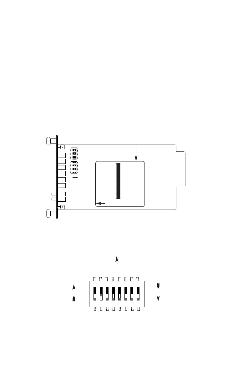
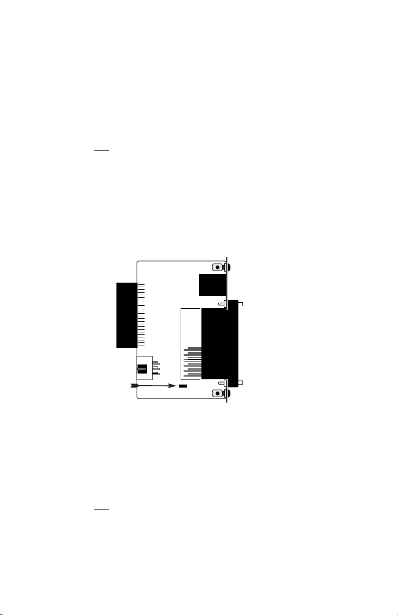
3.1 CONFIGURING THE HARDWARE SWITCHES
The Model 1092RC Series front card defaults
to the use of
hardware switches for configuration. There is an interface driver board
strap, and two eight-position DIP switches, on the front card (see
Figure 1, below).
Figure 2 shows the orientation of the DIP switches with respect to
the “ON” and “OFF” positions.
5
Figure 1. Model 1092RC, showing configuration switches and interface board
SW1
SW2
Interface
Driver
Board
THIS SIDE UP FOR V.35
FRONT
Figure 2. Close up of configuration switches (both sets are identical in appearance)
NOTE: The ON position is oriented toward the front of the Model 1092RC.
OFF
ON
Front Panel
ON OFF
ON
12345678
ON
12345678
ON
12345678
Page 7
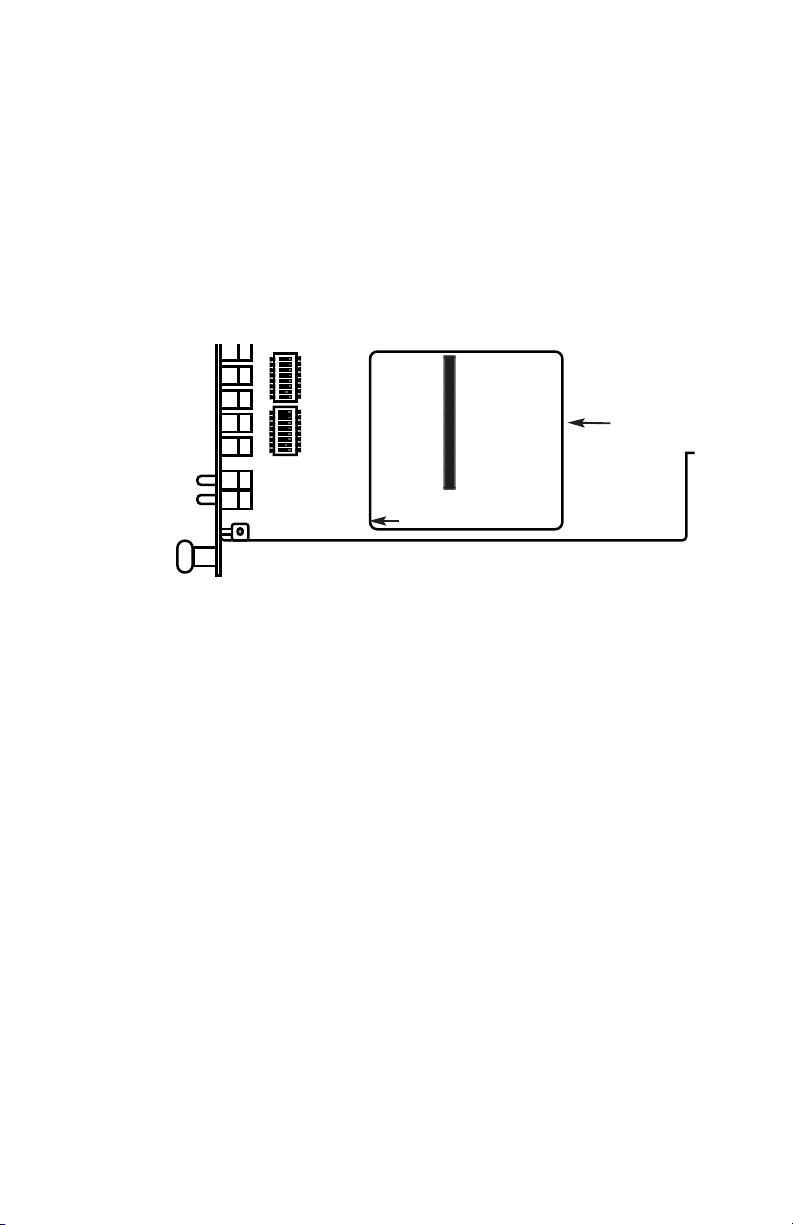
3.1.1 Reversible Interface Driver Board
The Model 1092RC Series features switchable interface driver
boards that allow a wide range of DTE interface connections. Each
interface driver board incorporates two interfaces -- one on each side
of the driver board. Figure 3 shows the Interface Driver Board on the
bottom of the 1092RC PC board.
Follow the instructions below to select the correct interface for your
application:
1. With the 1092RC pulled out of the rack or clusterbox chassis,
locate the driver board on the top of the 1092RC front card.
2. Lift the interface board gently off of the PC board.
3. Locate the correct interface on the bottom of the driver board.
For example, the RS-232/V.35 interface board is marked
“THIS SIDE UP FOR RS-232” on one side and “THIS SIDE
UP FOR V.35” on the other side .
4. Re-orient the interface board into the socket with the
appropriate interface pointed UP and with the arrow pointing
toward the front panel of the Model 1092RC PC board.
5. Push the Interface Driver Board gently onto the socket and reinstall into the rack or cluster system.
6
Figure 3. Closeup of Model 1092RC Interface Driver Board
Interface
Driver
Board
FRONT
THIS SIDE UP FOR V.35
ON
12345678
ON
12345678
Page 8
3.1.2 Configuration DIP Switch Set “S1”
The configuration switches on S1 allow you to specify the data
rate, async/sync data format, transmit clock source and response to
RDL request. Default settings of S1 are shown in the table below.
Switches S1-1 and S1-2: Data Rate
Use Switches S1-1and S1-2 to configure the data rate of the Model
1092RC. Each setting represents one synchronous data rate and one
asynchronous data rate.
S1-1
S1-2 Sync Data Rate Async Data Rate
On On 32 Kbps Reserved
Off On 56 Kbps Reserved
On Off 64 Kbps Reserved
Off Off 19.2 or 128 Kbps* 0 - 38.4 kbps
*NOTE: Model 1092RC operates either at a synchronous rate of
19.2 kbps
or
128 kbps depending on the orientation of Switch S2.
To operate synchronously at 19.2 kbps, set Switch S2-1 ON. To
operate at 128 kbps, set Switch S2-1 OFF. See Section 3.1.3 for
more information.
7
Position Function Factory Default
S1-1 Data Rate On
S1-2 Data Rate Off
S1-3 DSR during Local Line Loop On
S1-4 Async/Sync Data Format Off
S1-5 Async/Sync Data Format Off
S1-6 Tx Clock Source On
S1-7 Tx Clock Source On
S1 SUMMARY TABLE
64K Sync
}
}
Async/Sync
Internal Clock
}
DSR Enable
Page 9

Switch S1-3: Data Set Ready During Local Line Loopback Test
Use Switch S1-3 to control the behavior of the DSR signal at the
EIA interface during the local line loopback test.
S1-3
Setting Description
On Enabled DSR is on during local
line loop (default)
Off Disabled DSR is off during local
line loop
Switches S1-4 and S1-5: Async/Sync Operation
Use Switches S1-4 and S1-5 to configure the Model 1092 for
async/sync operation. Both switches must be set in the “Off” position.
There is no other valid setting.
S1-4
S1-5 Setting
Off Off Allows sync/async control
On Off Reserved
Off On Reserved
On On Reserved
Switches S1-6 and S1-7: Transmit Clock Source
Use Switches S1-6 and S1-7 to configure the 1092 for internal,
external, or receive recover clock mode.
S1-6
S1-7 Setting Description
On On Internal Transmit Clock
derived internally
Off On External Transmit Clock
derived from the
terminal interface
On Off Receive Recover Transmit clock derived
from the received line
signal
Off Off hardware reset
8
Important:
A pair of Model 1092s communicate synchronously
across the twisted pair line connection. Therefore, you must set
these switches whether your application is async or sync.
For X.21 or Async applications, please configure one Model 1092
for internal clock mode and the other Model 1092 for receive
recover clock mode.
Page 10
Switch S1-8: Respond to Local and Remote Loop from DTE
Use Switch S1-8 to determine whether the DTE can initiate a local
or remote loopback test. When Switch S1-8 is in the On position, the
DTE may activate a local or remote loopback test by raising the
appropriate interface signal (see Appendix C to determine the local and
remote loopback signals).
S1-8
Setting
On Respond to loop request from DTE Interface
Off Do not respond to loop request from DTE Interface
3.1.3 DIP Switch Set “S2” - Control Port Address and 19.2 kbps
Sync.
The Model 1092RC may be configured by a menu-driven software
system when used with the Patton Model 1000CC (for ordering
information, see Appendix B). In order to configure the Model 1092RC
by software commands, you must set its control port address.
The control port address is defined by a two digit decimal number.
Switches S2-1 through S2-4 define the least significant digit or the
“ones” digit, and Switches S2-5 through S2-7 define the “tens” digit.
Valid addresses are 0 through 79. Use the table below and the
instructions that follow the table to set the the control port to the desired
address.
9
S2 SUMMARY TABLE
Switch S2 Settings
1*2 345678
Address
Digit
0ONONONON
ON ON ON ON
1
OFF ON ON ON
OFF ON ON ON
2 ON OFF ON ON ON OFF ON ON
3 OFF OFF ON ON OFF OFF ON ON
4 ON ON OFF ON ON ON OFF ON
5 OFF ON OFF ON OFF ON OFF ON
6 ON OFF OFF ON ON OFF OFF ON
7 OFF OFF OFF ON OFF OFF OFF ON
8 ON ON ON ON N/A N/A N/A ON
NOTE: Default Settings Shown in Bold Italics; Default Address is “10”
Page 11

Switches S2-1, S2-2, S2-3, S2-4: Control Port Address -- LSD
Use Switches S2-1, S2-2, S2-3 and S2-4 to set the least
significant digit of the the Model 1092RC control port address. For
example, using the table above, if the desired address is “63”, the “3” is
the least significant digit in the address, set Switches S2-1, S2-2, S2-3
and S2-4 to OFF OFF ON ON, respectively.
*NOTE: You may also use Switch S2-1 to enable 19.2 kbps
synchronous operation by setting Switch S2-1 to the ON position.
However, when Switch S2-1 is in the ON position, LSD addresses
0, 2, 4, 6, and 8 may not be used for the Control Port Address.
Switches S2-5, S2-6, S2-7: Control Port Address -- MSD
Use Switches S2-5, 2-6 and S2-7 to set the most significant digit of
the Model 1092RC control port address. For example,using the table
above, if the desired address is “62”, the “6” is the most significant digit
in the address, set Switches S2-5, S2-6, and S2-7 to ON, OFF, OFF,
respectively.
Switch S2-8:
Reserved for Factory Use
Switch S2-8 is reserved for factory use and must in the ON position.
10
Page 12

3.2 CONFIGURING THE SOFTWARE SWITCHES
The Model 1092RC features a menu-driven command system that
allows you to configure either the local or remote 1092RC. The
software control port signals of the 1092RC are carried to each card in
the rack along the internal power bus board. Access to all rack card
control ports is provided by a single PATTON Model 1000CC Control
Card (see Model Model 1000CC User Manual). After setting the
control port address (Section 3.1.3), use the following instructions to
configure the unit:
1) Connect the serial RS-232 port of a V100 or similar DTE with
terminal emulation to the EIA-561 control port on the Model
1000CC control card. To construct an RS-232 to EIA-561
patch cable, refer to the control port pinout diagram in
Appendix D. Refer to Appendix C to order a pre-made cable.
2) Power up the terminal and set its RS-232 port as follows:
9600 Baud
8 data bits, i stop bit, no parity
Local echo
CR-CR/LF on inbound data
ANSI, VT-100 emulation
3. Press [CTRL+B] on the terminal followed by the two-digit
control port address and press [RETURN].
4. To make a selection from any menu, enter the option number.
To exit any menu without making a selection, press the [ESC]
key or the [SPACE] key.
5) After the Model 1092RC is powered on, the control port will
send out this message:
2W BBMRC, ver. x.x
6) Press [ESC] on the terminal.
7) The 1092RC will then display the MAIN MENU screen. You
may configure the LOCAL Model 1092RC from this screen.
To configure the REMOTE Model 1092RC, press ‘$’ (Shift-4
on most keyboards).
11
Important!!:
To make a selection from any menu, enter the option
number. To exit any menu without making a selection, or to return
to the previous menu, press the [ESC] key or the [SPACE] key.
Page 13

3.2.1 Configuring the Local 1092RC
To configure the local 1092RC, make a selection from the following
MAIN MENU. To configure the remote 1092 or 1092RC, type [$] (Shift-
4) and refer to Section 3.2.2.
MAIN MENU Option 1: Display Active Configuration
Select Option 1 to display the most recent configuration of the local
Model 1092RC (See below). The Model 1092RC uses the active
configuration for its operation. If you make changes to the
configuration, you must select MAIN MENU Option 8. This will update
the unit to the new active configuration.
3.2.2 MAIN MENU Option 2: Display Hardware Configuration
Select Option 2 to display the configuration of the hardware DIPswitches. To use the Hardware Configuration for the Active
Configuration, select MAIN MENU Option 5. Then select “Use
Hardware DIP-Switches”. Finally, select MAIN MENU Option 8 to save.
12
Page 14

MAIN MENU Option 3: Display Software Configuration
Select Option 3 to display the configuration of the software
switches. To use the software configuration for the Active
Configuration, select MAIN MENU, Option 5. Then select “Use
Software Switches”. Finally, select MAIN MENU Option 8 to save.
MAIN MENU Option 4: Setup Software Configuration
Select Option 4 toedit the software configuration of the Model
1092RC. To save changes after editing the software configuration,
select MAIN MENU Option 5, then select “Use Software Switches” and
then select MAIN MENU Option 8.
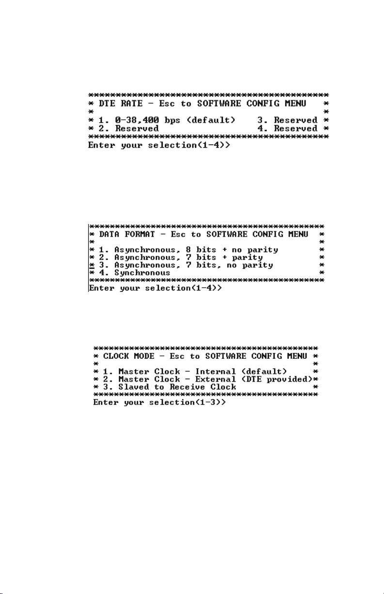
1. DTE Rate
Select Option 1 in the SOFTWARE CONFIGURATION menu to select
the async. or sync. DTE Rate of the Model 1092RC. Different DTE
Rate menu screens will display for async. or sync. bit rates. The
selections are shown below.
a) This menu is displayed when the data format is synchronous:
13
Page 15
b) This menu is displayed when the data format is asynchronous:
2. Data Format
Select Option 2 in the SOFTWARE CONFIGURATION Menu to
select the async or sync data format (See below). This option controls
whether the unit operates in asynchronous or asynchronous data
formats.
3. Clock Mode
Select Option 3 in the SOFTWARE CONFIGURATION Menu to
select the sync clock mode (See below).
Set this option as follows:
Master Clock - Internal: Selection 1 allows the Model
1092RC to generate an internal clock as the timing source.
Master Clock - External: Selection 2 allows the Model
1092RC to Derive the system clock from the locally connected
DTE.
Slaved to Receive Clock: Selection 3 to allows the Model
1092RC to derive the timing source from the incoming data
stream from the remote Model 1092RC.
14
Page 16
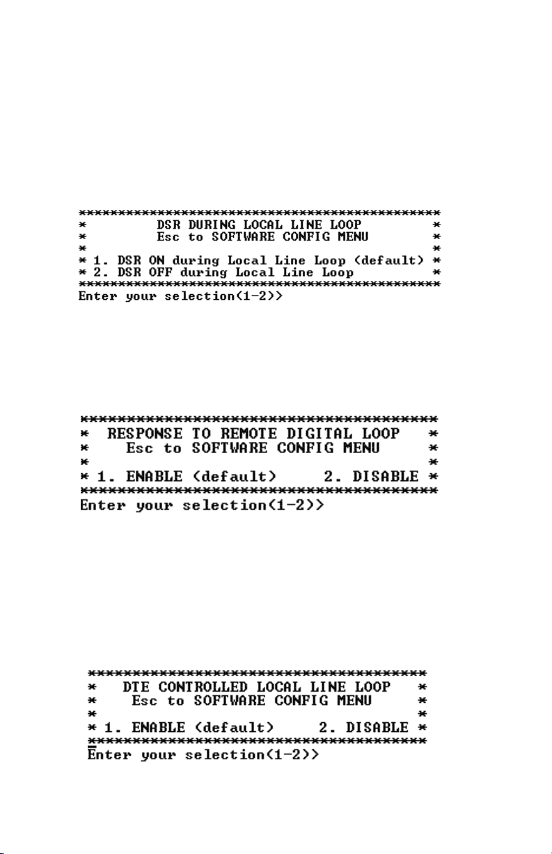
4. DSR During Local Line Loop
Select Option 4 in the SOFTWARE CONFIGURATION to configure
the behavior of the local Data Set Ready (DSR) signal during the Local
Line Loop test mode (below).
5. Response to Remote Digital Loop
Select Option 5 in the SOFTWARE CONFIGURATION Menu to
instruct the Model 1092RC to either respond or ignore the Remote
Digital Loop request from the remote 1092RC.
6. DTE Controlled Local Line Loop
Select Option 6 in the SOFTWARE CONFIGURATION Menu to
instruct the Model 1092RC to either respond or ignore Local Line Loop
requests from the DTE. To instruct the Model 1092RC to respond to
Local Line Loop requests from the DTE, select Enable (Option 1). To
instruct the 1092RC to ignore Local Line Loop requests from the DTE
interface, select Disable (Option 2).
15
Page 17
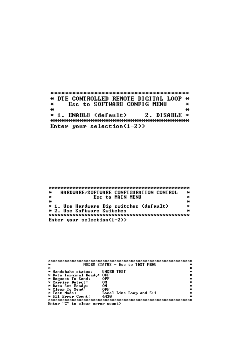
7. DTE Controlled Remote Digital Loop
Select Option 7 in the SOFTWARE CONFIGURATION Menu to
enable DTE control of the Remote Digital Loop Menu (See below). The
Remote Digital Loop on the 1092RC can be controlled from the DTE
interface by selecting Enable (Option 1). To instruct the 1092RC to
ignore this request from the DTE interface, select Disable (Option 2).
3.2.5 MAIN MENU Option 5: Select Hardware/Software Control
Select Option 5 from the MAIN MENU selects whether the Model
1092RC will use the hardware switch settings or the software switch
settings for its active configuration. If Options 1 or 2 are selected, the
1092RC will use the current hardware or software switch settings as the
active configuration. After changing this setting select MAIN MENU
Option 8 to implement the changes.
3.2.6 MAIN MENU Option 6: Display Modem Status
Select Option 6 from MAIN MENU to display the Modem Status
(below). Press RETURN on the keyboard to update and redisplay the
screen.
16
Page 18
Valid Model 1092RC Handshake status conditions are listed
below:
1. Handshaking - This status occurs when the 1092RC is in
the process of establishing a link with another 1092RC.
2. Data Mode - This status occurs when the 1092RC
successfully establishes a link with another 1092RC allowing
the data to flow.
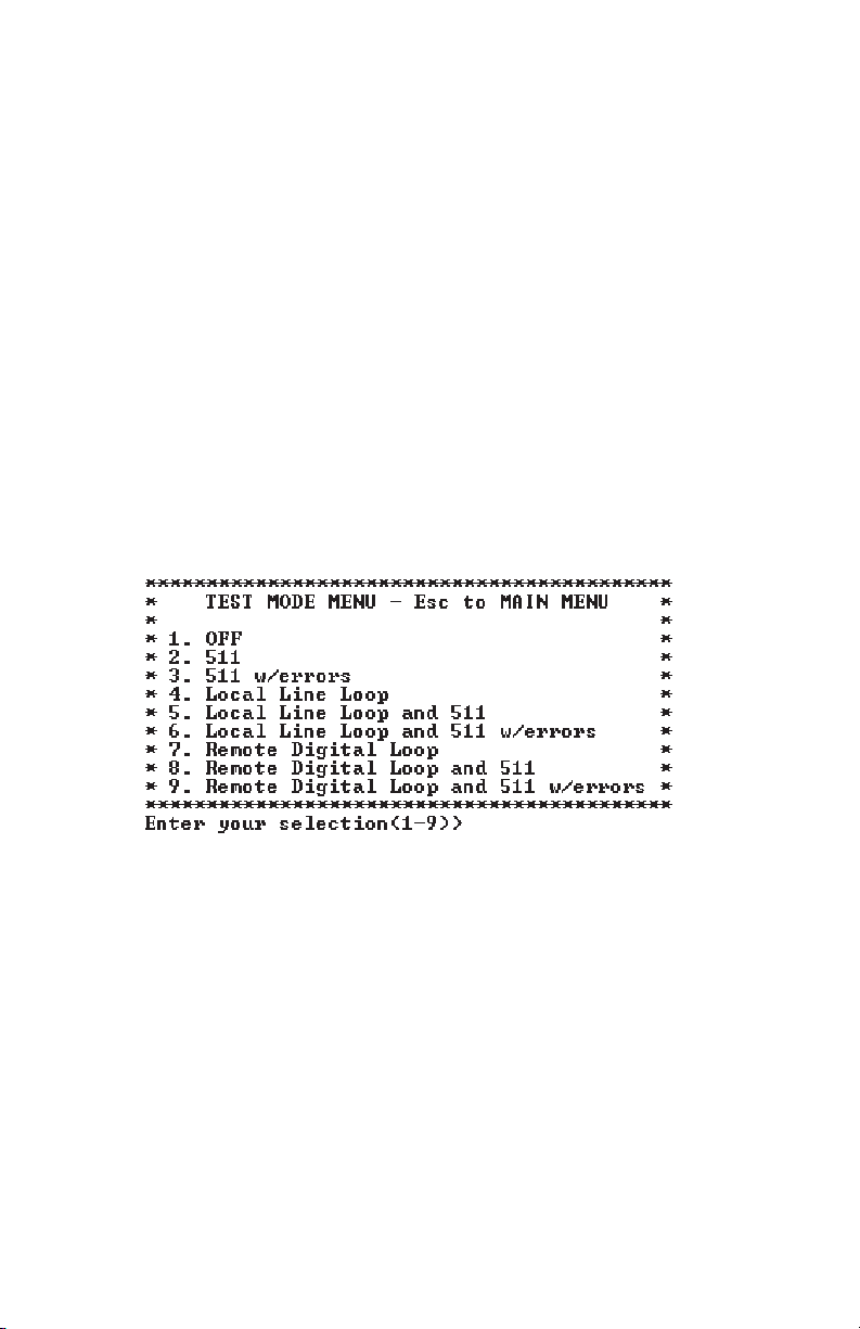
3.2.7 MAIN MENU Option 7: Test Modes
Select Option 7 from the MAIN MENU to select the test mode status
of the Model 1092RC. (below). The Model 1092RC Test Mode settings
help to verify the integrity of the data link and isolate communication
difficulties.
NOTE: The 1092RC control port displays an error counter in
all test modes except options 4 and 7 listed above.
To run or terminate a particular test, key in the option to get to that
screen menu. If a particular test cannot be invoked, the unit displays
the message:
“Attempt unsuccessful!”.
17
Page 19

Test Mode options 2,3,7,8 and 9 require the 1092RC to be in Data
Mode with the remote 1092RC. The Model 1092RC Test Modes are
described below:
OFF Terminates all tests
511 Initiates the built-in test pattern generator
and detector.
511 with Errors Initiates the built-in test pattern generator
and detector. The test pattern generator
also injects intentional errors approximately
once per second.
Local Line Loop Initiates the Local Line Loop test and starts
and 511 the internal 511 generator and detector.
Local Line Loop Initiates the Local Line Loop test and starts
and 511 w/errors the internal 511 generator and detector. In
this test, the 511 pattern generator injects
intentional errors into the data stream.
Remote Digital Initiates the Remote Digital Loopback test.
Loop Any data sent to the remote 1092RC is
returned to the originating device.
Remote Digital Initiates the Remote Digital Loopback test
Loop and 511 and starts the internal 511 generator and
detectors.
Remote Digital Initiates the Remote Digital Loopback test
Loop and and starts the 511test patterns. In this test
511 with errors the 511 pattern generator will inject initial
errors into the data stream.
The Modem Status Screen is displayed upon initiating a test. A
511 error counter is displayed to indicate errors. Press the ‘C’ key to
clear the counter and redisplay the Modem Status Screen. Pressing
‘ESC’ returns you to the Test Mode Menu.
18
Page 20
3.2.2 Configuring the Remote 1092RC
To configure the remote 1092RC, make a selection from the
following REMOTE UNIT CONFIGURATION MAIN MENU. To return to
the LOCAL 1092RC MAIN MENU screen, press [ESC] and refer to
Section 3.2.1.
REMOTE MAIN MENU Option 1: Display Remote Unit Configuration
Select Option 1 to display the configuration of various parameters in
the remote Model 1092RC.
19
REMOTE UNIT CONFIGURATION
MAIN MENU
1. Display Remote Unit Configuration
2. Setup Remote Unit Configuration
3. Display Remote Modem Status
4. Select Hardware /Software Control
5. Restart Remote Unit
REMOTE CONFIGURATION
CONFIGURATION DISPLAY MENU
1. Display Configuration of:
DSR during Local Line Loop
Response to Remote Digital Loop
Clock Mode
2. Display Configuration of:
Configuration Control
DTE Rate
3. Display Configuration of:
DTE Controlled Local Line Loop
DTE Controlled Remote Digital Loop
Page 21
REMOTE MAIN MENU Option 2: Remote Unit Configuration
REMOTE MAIN MENU Option 2 allows you to edit the software
configuration of the REMOTE Model 1092RC. Please note that after
editing the software configuration, you must select REMOTE MAIN
MENU Option 4, the select “Use Software Switches” and then select
MAIN MENU Option 5 to implement the most recent changes.
REMOTE MAIN MENU Option 3: Display Remote Modem Status
Select REMOTE MAIN MENU Option 3 to display the status of the
REMOTE unit.
REMOTE MAIN MENU Option 4: Display Hardware/Software Control
Select REMOTE MAIN MENU Option 4 to select whether the
remote Model 1092RC will use the hardware switch settings or the
software switch settings for its active configuration.
REMOTE MAIN MENU Option 5: Restart Remote Unit
Select REMOTE MAIN MENU Option 5 to restart the remote
unit.
20
REMOTE UNIT CONFIGURATION MENU
1. DTE Rate
2. Clock Mode
3. DSR during Local Line Loop
4. Response Remote Digital Loop
5. DTE Controlled Local Line Loop
6. DTE Controlled Remote Digital Loop
7. 2-Wire/4-Wire Selection (ONLY FOR 1092A)
NOTE: All REMOTE CONFIGURATION sub-menus are
similar to the LOCAL CONFIGURATION sub-menu
screens. See Section 3.2.1 for details.
Page 22
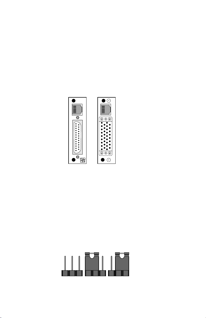
3.3 CONFIGURING THE REAR INTERFACE CARD
The Model 1092RC Series has two interface card options: the
Model 1000RCM12592 (DB-25/RJ-45) and the Model 1000RCM13492
(M/34/RJ-45). Each of these options supports one DTE interface
connection and one 2-wire line connection. Figure 4 below illustrates
the two different interface options for the Model 1092RC Series.
NOTE: The 1092RC Series rear cards are specifically designed to
operate with the Model 1092RC function card and must not be
swapped with other Patton function cards.
Prior to installation, you will need to examine the rear card you
have selected and make sure it is properly configured for your
application. Each rear card is configured by setting straps located on
the PC board. To configure the rear cards, you must set the
configuration straps. Figure 5 below shows the orientation of these
straps. Each strap can either be on pegs 1 and 2, or on pegs 2 and 3.
Sections 3.3.1 and 3.3.2 describe the strap locations and possible
settings for each rear card.
21
Figure 4. Model 1092RC Series interface card options
DB-25 F
M/34 F
Figure 5. Orientation of Interface Card Straps
connected
open
RJ-45
RJ-45
Model
1000RCM12592
Model
1000RCM13492
123 123 123
Page 23

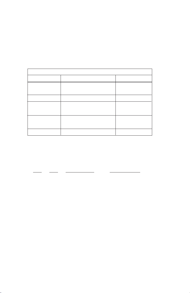
3.3.1 Model 1000RCM12592 Strap Settings
Figure 6 shows strap locations for the Model 1000RCM12592
(DB-25/RJ-45S) rear cards. These straps determine various grounding
characteristics for the terminal interface and twisted pair lines. JB3
and JB4 are user configurable. JB2 must
be set on pegs 1 and 2.
The table below provides an overview of interface strap functions
for the rear interface cards. Following the table overview are detailed
descriptions of each strap’s function.
DTE Shield (DB-25 Pin 1) & FRGND (JB3)
In the connected position, this strap links DB-25 pin 1 & frame
ground. In the open position, pin 1 is disconnected from frame ground.
JB3
Position 1&2 = DTE Shield (Pin 1) and FRGND Connected
Position 2&3 = DTE Shield (Pin 1) and FRGND Not Connected
22
Figure 6. DB-25/RJ-45S strap locations
JB3
JB4
JB2
INTERFACE CARD STRAP SUMMARY TABLE #1
Strap Function Position 1&2 Position 2&3
JB3 DTE Shield (Pin1) & FRGND Connected Open*
JB4 FRGND & SGND Connected Open*
* Indicates default setting
123
123
123
Page 24
SGND & FRGND (JB4)
In the connected position, this strap links DB-25 pin 7 (Signal
Ground) and frame ground. In the open position, pin 1 is disconnected
from frame ground.
JB4
Position 1&2 = SGND (Pin 7) and FRGND Connected
Position 2&3 = SGND (Pin 7) and FRGND Not Connected
3.3.2 Model 1000RCM13492 Strap Settings
Figure 7 shows the strap location for the Model 1000RCM13492
(M/34/RJ-45) rear card. This strap determines whether Signal Ground
and Frame Ground will be connected.
SGND & FRGND (JB4)
In the connected position, this strap links Signal Ground and frame
ground. In the open position, signal ground is disconnected from frame
ground.
JB4
Position 1&2 = SGND and FRGND Connected
Position 2&3 = SGND and FRGND Not Connected
23
Figure 7. M/34/RJ-45 strap locations
JB4
123
Page 25
4.0 INSTALLATION
This section describes the functions of the Model 1000R16 rack
chassis, tells how to install front and rear Model 1092RC Series cards
into the chassis, and how to connect to the twisted pair interface and
the serial interface.
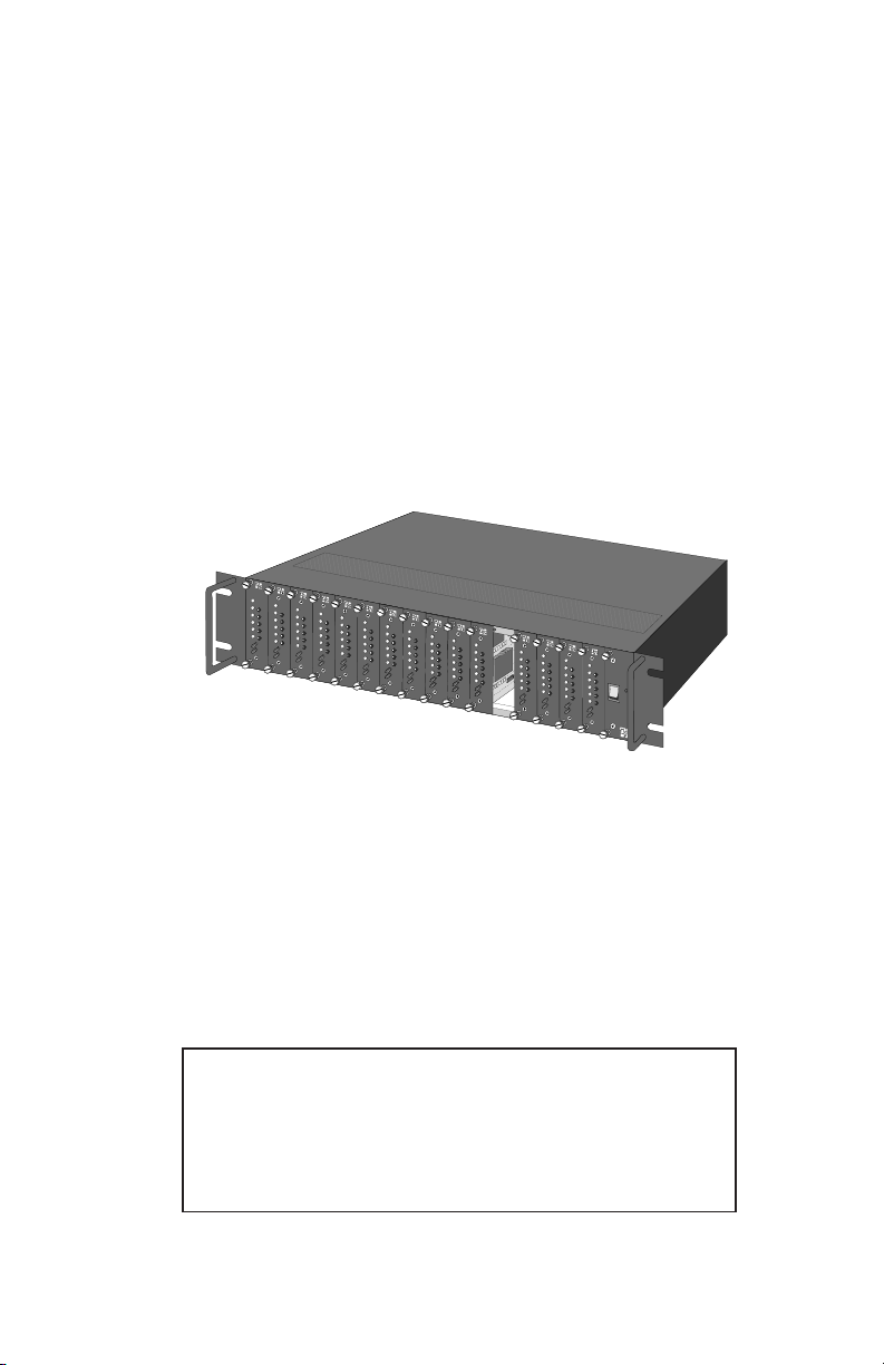
4.1 THE MODEL 1000R16 RACK CHASSIS
The Model 1000R16 Rack Chassis (Figure 8, below) has sixteen
short range modem card slots, plus its own power supply. Measuring
only 3.5” high, the Model 1000R16 is designed to occupy only 2U in a
19” rack. Sturdy front handles allow the Model 1000R16 to be
extracted and transported conveniently.
4.1.1 The Rack Power Supply
The power supply included in the Model 1000R16 rack uses the
same mid-plane architecture as the modem cards. The front card of
the power supply slides in from the front, and the rear card slides in
from the rear. They plug into one another in the middle of the rack.
The front card is then secured by thumb screws and the rear card by
conventional metal screws.
24
Figure 8: Model 1000R16 Rack Chassis with power supply
WARNING! There are no user-serviceable parts in the
power supply section of the Model 1092RC Series.
Voltage setting changes and fuse replacement should only
be performed by qualified service personnel. Contact
Patton Electronics Technical support at (301)975-1007 for
more information.
Page 26

Switching the Power Supply On and Off
The power switch is located on the front panel. When plugged in
and switched on, a red front panel LED will glow. Since the Model
1000R16 is a "hot swappable" rack,
it is not necessary for any cards to
be installed before switching on the power supply
. The power supply
may be switched off at any time without harming the installed cards.
NOTE: Please refer to the Model 1000RP Series User Manual
AC
and DC Rack Mount Power Supplie
s for fuse and power card
replacement information.
4.2 INSTALLING THE MODEL 1092RC SERIES INTO THE CHASSIS
The Model 1092RC Series is comprised of a front card and a rear
card. The two cards meet inside the rack chassis and plug into each
other by way of mating 50 pin card edge connectors. Use the following
steps as a guideline for installing each Model 1092RC Series into the
rack chassis:
1. Slide the rear card into the back of the chassis along the metal
rails provided.
2. Secure the rear card using the metal screws provided.
3. Slide the front card into the front of the chassis. It should
meet the rear card when it’s almost all the way into the
chassis.
4. Push the front card
gently
into the card-edge receptacle of the
rear card. It should “click” into place.
5. Secure the front card using the thumb screws.
4.3 WIRING THE MODEL 1092RC SERIES
Each of the rear interface cards compatible with the Model
1092RC Series has one terminal interface port and one 2-wire (twisted
pair) port. For specific interface pin-outs, refer to the diagrams in
Appendix C of this manual.
.
25
Page 27
4.3.1 Connection to a “DTE” Device
Regardless of the interface module you choose, the Model
1092RC’s serial port is always wired as a DCE. Therefore it “wants” to
plug into a DTE such as a terminal, PC or host. When making the
connection to your DTE device, use a
straight through
cable of the
shortest possible length that is appropriate to the interface you are
using. When purchasing or constructing an interface cable, please
refer to the pin diagrams in Appendix C as a guide.
4.3.2 Connection to a “DCE” Device
Since the Model 1092RC’s serial port is always wired as a DCE,
you must use a
null modem
cable when connecting to another DCE
device such as a CSU/DSU, modem or multiplexer. This cable should
be of the shortest possible length that is appropriate to the interface you
are using. When purchasing or constructing a null modem interface
cable, use the pin diagrams in Appendix C as a guide.
4.3.3 Connection to the Twisted Pair Interface
The Model 1092RC supports communication between two DTE
devices at distances to 5 miles (8 km) over 24AWG (.5mm) twisted pair
wire. There are two essential requirements for installing the Model
1092RC:
1. These units work in
pairs
. Therefore, you must have one
Model 1092RC (or a compatible model) at each end of a single
twisted pair interface.
2. To function properly, the Model 1092RC needs one twisted
pair of metallic wire. This twisted pair must be
unconditioned
,
dry, metallic wire, between 19 (.9mm) and 26 AWG (.4mm) (the
higher number gauges may limit distance somewhat). Standard
dial-up telephone circuits, or leased circuits that run through signal
equalization equipment, or standard, flat modular telephone type
cable, are
not acceptable
..
26
Notice! Any terminal cable connected to the Model
1092RC must be shielded cable, and the outer shield must
be 360 degree bonded–at both ends–to a metal or
metalized backshell.
Page 28

4.3.4 Two-Wire Cable Connection Via RJ-45
1. The RJ-45 connector on the Model 1092RC’s twisted pair
interface is polarity insensitive and is wired for a two-wire
interface. The signal/pin relationships are shown in Figure 9
below.
2. Proper wiring of pairs between the two modems is as follows:
SIGNAL
PIN# PIN# SIGNAL
TIP 4--------------------------------------------- 4 TIP
RING 5--------------------------------------------- 5 RING
4.3.5 Connection to the Control Port Interface
Please refer to the Model 1000CC Control Card user manual for
cable requirements of the Control Port Interface.
27
Notice! Any modular twisted pair cable connected to
the Model 1092RC must be shielded cable, and the outer
shield must be properly terminated to a shielded modular
plug on both ends of the cable.
Figure 9. Model 1092RC twisted pair line interface.
1 (N/C)
2 (GND)
3 (N/C)
4 (Tip)
5 (Ring)
6 (N/C)
7 (GND)
8 (N/C)
1
2
3
4
5
6
7
8
Page 29

5.0 OPERATION
Once the Model 1092RC is properly configured and installed, it
should operate transparently. This sections describes functions of the
LED status indicators, and the use of the built-in loopback test modes.
5.1 LED STATUS INDICATORS
The Model 1092RC features twelve front panel LEDs that monitor
power, the DTE signals, network connection and test modes. Figure 10
(below) shows the front panel location of each LED. Following Figure
10 is a description of each LEDs function.
TD & RD glow red to indicate an idle condition of Binary
“1” data on the respective terminal interface
signals. Green indicates Binary “0” data.
CTS consists of 2 LEDs, 1 red, 1 green. CTS glows
green to indicate that the Clear to Send signal from
the modem is active. Red indicates inactive CTS.
CD consists of 2 LEDs, 1 red, 1 green. CD glows
red if no carrier signal is being received from the
remote modem. Green indicates that the remote
modem’s carrier is being received.
DTR glows green to indicate that the Data Terminal
Ready signal from the terminal is active.
28
Figure 10. The Model 1092RC Series' front panel LEDs
Model 1092RC
TD
RD
CTS
CD
NS
DTR
ER
TM
LLB
RDL
511
511ER
Page 30

ER glows red to indicate the likelihood of a Bit Error
in the received signal. During the 511 or 511/E
test, ER flashes to indicate that the Test Pattern
Detector has detected a bit error.
TM glows red to indicate that the Model 1092RC
has been placed in Test Mode. The unit can be
placed in test mode by the local user or by the
remote user.
NS (No Signal) glows red to indicate that the local
Model 1092RC has not yet connected with the
remote Model 1092RC.
5.2 TEST MODES
The Model 1092RC offers two proprietary loopback test modes,
plus a built-in V.52 BER test pattern generator, to evaluate the condition
of the modems and the communication link. These tests can be
activated physically from the front panel, or via the interface.
5.2.1 Using Local Line Loopback (LLB)
The Local Line Loopback (LLB) test checks the operation of the
local Model 1092RC, and is performed separately on each unit. Any
data sent to the local Model 1092RC in this test mode will be echoed
(returned) back to the user device (see Figure 11, below). For
example, characters typed on the keyboard of a terminal will appear on
the terminal screen.
To perform an LLB test, follow these steps:
1. Activate LLB. This may be done in one of two ways: First, by
moving the front panel toggle switch to the right to “Local”.
Second, by raising the LLB signal on the interface (see
Appendix C). Once LLB is activated, the Model 1092RC
transmitter output is connected to its own receiver. The “TM”
LED should be lit.
29
Figure 11 Local Line Loopback
1092RC
1090
Page 31

NOTE: Switch S1-8 must be in the “ON” position).
2. Verify that the data terminal equipment is operating properly
and can be used for a test.
3. Perform a V.52 BER (bit error rate) test as described in
Section 5.2.3. If the BER test equipment indicates no faults,
but the data terminal indicates a fault, follow the
manufacturer’s checkout procedures for the data terminal.
Also, check the interface cable between the terminal and the
Model 1092RC.
5.2.2 Using Remote Digital Loopback (RDL)
The Remote Digital Loopback (RDL) test checks the performance
of both the local and remote Model 1092RCs, and the communication
link between them. Any characters sent to the remote Model 1092RC
in this test mode will be returned back to the originating device (see
Figure 12, below). For example, characters typed on the keyboard of
the local terminal will appear on the local terminal screen after having
been passed to the remote Model 1092RC and looped back.
To perform an RDL test, follow these steps:
1. Activate RDL. This may be done in two ways: first, by moving
the front panel toggle switch to the Left to “Remote”. Second,
by raising the RDL signal on the interface (see Appendix C).
NOTE: Switch S1-8 must be in the “ON” position.
2. Perform a V.52 BER test as described in Section 5.2.3. If the
BER test equipment indicates a fault, and the Local Line
Loopback test was successful for both Model 1092RCs, you
may have a problem with the twisted pair line between the
modems. You should then check the twisted pair line for
proper connections and continuity.
30
Figure 12. Remote Digital Loop
Local 1092RC
Remote 1092RC
Page 32

5.2.3 Using the V.52 (BER) Test Pattern Generator
To use the V.52 BER tests in conjunction with the Remote Digital
Loopback tests* (or with Local Line Loopback tests), follow these
instructions:
1. Locate the “511/511E” toggle switch on the front panel of the
1092RC and move it to the left. This activates the V.52 BER
test mode and transmits a “511” test pattern into the loop. If
any errors are present, the local modem’s red “ER” LED will
blink sporadically.
2. If the above test indicates no errors are present, move the
V.52 toggle switch to the right, activating the “511/E” test with
errors present. If the test is working properly, the local
modem's red “ER” LED will glow. A successful “511/E” test
will confirm that the link is in place, and that the Model
1092RC’s built-in “511” generator and detector are working
properly.
*NOTE: The above V.52 BER tests can be used independently of
the Remote Digital Loopback tests. This requires two operators:
one to initiate and monitor the tests at the local Model 1092RC,
and one to do the same at the remote Model 1092RC. In this
case, the test pattern sent by each Model 1092RC will not be
looped back, but will be transmitted down the line to the other
Model 1092RC.
31
Page 33

APPENDIX A
PATTON MODEL 1092RC SPECIFICATIONS
Transmission
Format: Synchronous or asynchronous
Transmission Line: Single unconditioned twisted pair
Clocking: Internal, external or receive recover
Distance: Up to 10.8 miles (17.3Km), all data rates, 19
AWG (.9mm)
Up to 7.2 miles (11.5Km), all data rates, 22
AWG (.6mm)
Up to 5 miles (8Km), all data rates, 24AWG
(.55mm)
Up to 3.41 miles (5.45Km), all data rates, 26
AWG(.4mm)
Data Rates:
Sync
32, 56, 64 & 128 kbps;
Async
0 - 38.4 kbps
Diagnostics: V.52 compliant bit error rate pattern
(511/511E pattern) generator and detector
with error injection mode; Local Line
Loopback and Remote Digital Loopback,
activated by front panel switch or via serial
interface
LED Indicators: TD, RD, CTS, CD, DTR, NS(no signal),
ER (error) and TM (test mode)
Connectors: RJ-45 on line side; DB-25 female or M/34
female on serial interface side, depending
upon which interface rear card is installed.
Temperature: 32-140°F (0-60°C)
Altitude: 0-15,000 feet (0-4572 meters)
Humidity: 5 to 95% noncondensing
Dimensions: Front Card: 4.81” x 3.10” x 0.95”
(12.2 x 7.8 x 2.4cm)
Rear Card: 3.33” x 2.8” x 0.95”
(8.4 x 7.1 x 2.4cm)
Weight: Front Card: 0.22 lbs (.10Kg)
Rear Card (M/34 with V.35 interface): 0.16
lbs (.07Kg)
Rear Card (DB-25/RS-232 interface): 0.12
lbs. (.05Kg)
32
Page 34

APPENDIX B
PATTON MODEL 1092RC
FACTORY REPLACEMENT PARTS
AND ACCESSORIES
Patton Model #
Description
1000RCM12592.........Rear card w/DB25F & RJ45 (V.24 interface)
1000RCM12492.........Rear card w/ M/34F & RJ45 (V.35 interface)
1000RPEM ................120/240V Rear Power Entry Module
1000RPSM-2 .............120/240V Front Power Supply Module
1000RPEM-DC..........DC Rear Power Entry Module
1000RPSM-48A.........48V Front Power Supply Module
1000RPEM-V.............120/240V CE Compliant Rear Power
Entry Module
1000RPEM-V.............120/240V CE Compliant Rear Power
Supply Entry Module
1000CC......................Control Card
IM1RC/A ....................Interface daughter card, V24/V.35
0805US......................American Power Cord
0805EUR ...................European Power Cord CEE 7
0805UK......................United Kingdom Power Cord
0805AUS ...................Australia/New Zealand Power Cord
0805DEN ...................Denmark Power Cord
0805FR......................France/Belgium Power Cord
0805IN .......................India Power Cord
0805IS .......................Israel Power Cord
0805JAP ....................Japan Power Cord
0805SW.....................Switzerland Power Cord
33
Page 35

34
APPENDIX C
MODEL 1092RC TERMINAL INTERFACE PIN ASSIGNMENT
M/34F Connector-DCE
(V.35 Interface)
Pin #
Signal
B ...........................SGND (Signal Ground)
C ...........................RTS (Request to Send)
D ...........................CTS (Clear to Send)
E ...........................DSR (Data Set Ready)
F............................CD (Carrier Detect)
H ...........................DTR (Data Transfer Ready)
L....................................LLB (Local Line Loop)
M ...........................TM (Test Mode)
N ...........................RDL (Remote Digital Loop)
P ...........................TD(Transmit Data)
R ...........................RD (Receive Data)
S ...........................TD/ (Transmit Data-B)
T............................RD/ (Receive Data-B)
U ...........................XTC (External Transmit Clock)
V ...........................RC(Receive Timing)
W ...........................XTC/ (External Transmit Clock)
X ...........................RC/ (Receive Timing)
Y ...........................TC(Test Control-A)
AA ..........................TC/ (Test Control-B)
Page 36

APPENDIX C (Continued)
PATTON MODEL 1092RC
TERMINAL INTERFACE PIN ASSIGNMENT
DB-25F Connector-DCE
(RS-232 Interface)
Pin #
Signal
1...........................FG (Frame Ground)
2.......................... TD (Transmit Data)
3...........................RD (Receive Data)
4...........................RTS (Request to Send)
5...........................CTS (Clear to Send)
6...........................DSR (Data Transfer Rate)
7...........................SGND (Signal Ground)
15.........................TC (Test Control-A)
17.........................RC (Receive Timing)
18.........................LLB (Local Line Loop)
20.........................DTR (Data Transfer Rate)
21.........................RDL (Remote Digital Loop)
24.........................XTC (External Transmit Clock
25.........................TM (Test Mode)
35
Page 37

APPENDIX D
PATTON MODEL 1092RC
CONTROL PORT PIN ASSIGNMENT
(RJ-45 CONNECTOR ON 1000CC CARD)
Pin Function
RJ-45 Pin Number
Transmit data (from DTE)................................7
Receive date (to DTE).....................................6
Ground.............................................................5
36
Page 38

APPENDIX E
LINE INTERFACE PIN ASSIGNMENT
(RJ45 Connector)
Pin Number
Signal
1...................................................N/C (No Connection)
2...................................................N/C (No Connection)
3...................................................N/C (No Connection)
4...................................................Tip
5....................................................Ring
6....................................................N/C (No Connection)
7....................................................N/C (No Connection)
8....................................................N/C (No Connection)
© Copyright 1997
Patton Electronics Company
All Rights Reserved
37
Page 39

Page 40

Dear Valued Customer,
Thank you for purchasing Patton Electronics products! We do appreciate
your business. I trust that you find this user manual helpful.
We manufacture one of the widest selections of data communications
products in the world including CSU/DSU's, network termination units,
powered and self-powered short range modems, fiber optic modems, interface
converters, baluns, electronic data switches, data-line surge protectors,
multiplexers, transceivers, hubs, print servers and much more. We produce
these products at our Gaithersburg, MD, USA, facility, and can custom
manufacture products for your unique needs.
We would like to hear from you. Please contact us in any of the following
ways to tell us how you like this product and how we can meet your product
needs today and in the future.
Web: http://www.patton.com
Sales E-mail: sales@patton.com
Support E-mail: support@patton.com
Phone - Sales (301) 975-1000
Phone - Support (301) 975-1007
Fax: (301) 869-9293
Mail: Patton Electronics Company
7622 Rickenbacker Drive
Gaithersburg, MD 20879 USA
We are committed to a quality product at a quality price. Patton
Electronics is ISO 9001 certified. We meet and exceed the highest standards
in the industry (CE, UL, etc.).
It is our business to serve you. If you are not completely satisfied with this
product or service provided by Patton Electronics or its distributors, please let
us know.
Thank you.
Burton A.Patton
Vice President
P.S. Please tell us where you purchased this product.
_________________________________________________________
_________________________________________________________
_________________________________________________________
_________________________________________________________
_________________________________________________________
_________________________________________________________
_________________________________________________________
 Loading...