

Page 1

B
LINE DRIVER, MULTI-DROP, 128K BPS
Doc #: 141001UA
Part #: 07M1084-A
1084
(CTS LD-128K)
INSTALLATION AND OPERATIONS MANUAL
September 7, 1995
An ISO-9001
Certified Company
Copyright© 2000 Patton Electronics Co., All Rights Reserved
Page 2

PATTON ELECTRONICS CO. 1084 INSTALLATION AND OPERATIONS MANUAL
141001UA
COPYRIGHT NOTICE
Copyright© 2000 Patton Electronics Co., All Rights Reserved.
PROPRIETARY NOTICE
The information contained herein is proprietary and confidential to Patton Electronics Co.
Any reproduction or redistribution of this publication, in whole or in part, is expressly
prohibited unless written authorization is given by Patton Electronics Co.
WARRANTY NOTICE
WARRANTIES: Patton Electronics Co. (hereafter referred to as Patton) warrants that its
equipment is free from any defects in materials and workmanship. The warranty period
shall be two years from the date of shipment of equipment. Patton’s sole obligation under
its warranty is limited to the repair or replacement of the defective equipment, provided it is
returned to Patton, transportation prepaid, within a reasonable period. This warranty will
not extend to equipment subjected to accident, misuse, alterations or repair not made by
Patton or authorized by Patton in writing.
PUBLICATION NOTICE
This manual has been compiled and checked for accuracy. The information in this manual
does not constitute a warranty of performance. Patton reserves the right to revise this
publication and make changes from time to time in the content thereof. Patton assumes no
liability for losses incurred as a result of out-of-date or incorrect information contained in
this manual.
i
Page 3

PATTON ELECTRONICS CO.INSTALLATION AND OPERATIONS MANUAL
141001UA
1084
EMISSION REQUIREMENTS
FCC CLASS A
Warning: Changes or modifications to this unit not expressly approved by the party
responsible for compliance could void the user’s authority to operate the equipment.
NOTE: This equipment has been tested and found to comply with the limits for a Class A
digital device, pursuant to Part 15 of FCC rules. These limits are designed to provide
reasonable protection against harmful interference when the equipment is operated in a
commercial environment. This equipment generates, uses, and can radiate radio frequency
energy and, if not installed and used in accordance with the instruction manual, may
cause harmful interference to radio communications. Operation of this equipment in a
residential area is likely to cause harmful interference in which case the user will be
required to correct the interference at his own expence.
CANADIAN EMISSIONS
This digital apparatus does not exceed the Class A limits for noise emmissions from a
digital apparatus set out in the Radio Interference Regulations of the Canadian Department
of Communications.
Le present appareil numerique n’emet pas de bruits redioelectriques depassant les limites
applicables aux appareils numeriques de la Class A prescites dans le Reglement sur le
brouillage redioelectrique edicte par le ministere des Communications du Canada.
ii
Page 4

PATTON ELECTRONICS CO. 1084 INSTALLATION AND OPERATIONS MANUAL
141001UA
Table of Contents
CHAPTER 1 - OPERATION
Front Panel ......................................................................................................................... 1-1
Point to Point / Multi-Point Operation ................................................................................. 1-1
“Switch on Data” Mode ....................................................................................................... 1-2
Clocking ....................................................................................................................... ....... 1 -2
Four Wire / Two Wire Operation......................................................................................... 1 -2
Testing Modes .................................................................................................................... 1-2
CTS Delays......................................................................................................................... 1-2
Anti-Streaming ................................................................................................................. ... 1-2
CHAPTER 2 - SETUP AND INSTALLATION
Power Connection .............................................................................................................. 2-1
Factory Configuration Switch Settings ............................................................................... 2 -1
Disassembly .................................................................................................................... .... 2-2
Installation........................................................................................................................... 2-2
Equipment Grounding (SW2-6) .......................................................................................... 2-2
Point to Point / Multi-Drop Connectors J2 & J3.................................................................. 2- 2
Full / Half Duplex Selection (SW2-2).................................................................................. 2 -3
Two Wire / Four Wire (JP4 & JP5) ..................................................................................... 2-3
Baud Rate Selection (SW1-1,2,3,4) ................................................................................... 2-3
“Switch on RS” or “Switch on Data” Mode (SW2-1)........................................................... 2 -4
CTS Delay Selection When “Switch on RS” is Enabled (SW1-5,6) ................................... 2 -4
Carrier Control (SW4-1) ...................................................................................................... 2 -4
Receiver Termination (SW4-5)........................................................................................... 2- 4
Transmit Clock Source (SW4-2,3) ...................................................................................... 2-4
Sync or Async Operation (SW4-4) ..................................................................................... 2-5
Anti-Streaming (SW2-3,4,5) ............................................................................................... 2-5
Factory Straps (JP1,JP2,JP3) ............................................................................................ 2-5
APPENDIX
TECHNICAL SPECIFICATIONS ........................................................................................ A-1
RS-232 Pin Out...................................................................................................................A-2
Application Diagram ............................................................................................................ A-2
Rear Panel View .................................................................................................................A-2
Four Wire Hookup “Point to Point” .....................................................................................A-3
Two Wire Hookup “Point to Point” ......................................................................................A-3
Four Wire Hookup “Multi-Point”..........................................................................................A-3
Two Wire Hookup “Multi-Point” ..........................................................................................A-3
iii
Page 5
PATTON ELECTRONICS CO. 1084 INSTALLATION AND OPERATIONS MANUAL
141001UA
CHAPTER 1 - OPERATION
The 1084 (CTS LD-128K) is an RS-232 Line Driver. This device is a cost effective solution
for interconnection of Synchronous or Asynchronous, Point to Point, or up to 32 Multi-Point,
terminal devices. (Distances of up to 4000 feet, at 128Kbps may be acheived, using 24ga.
wire.)
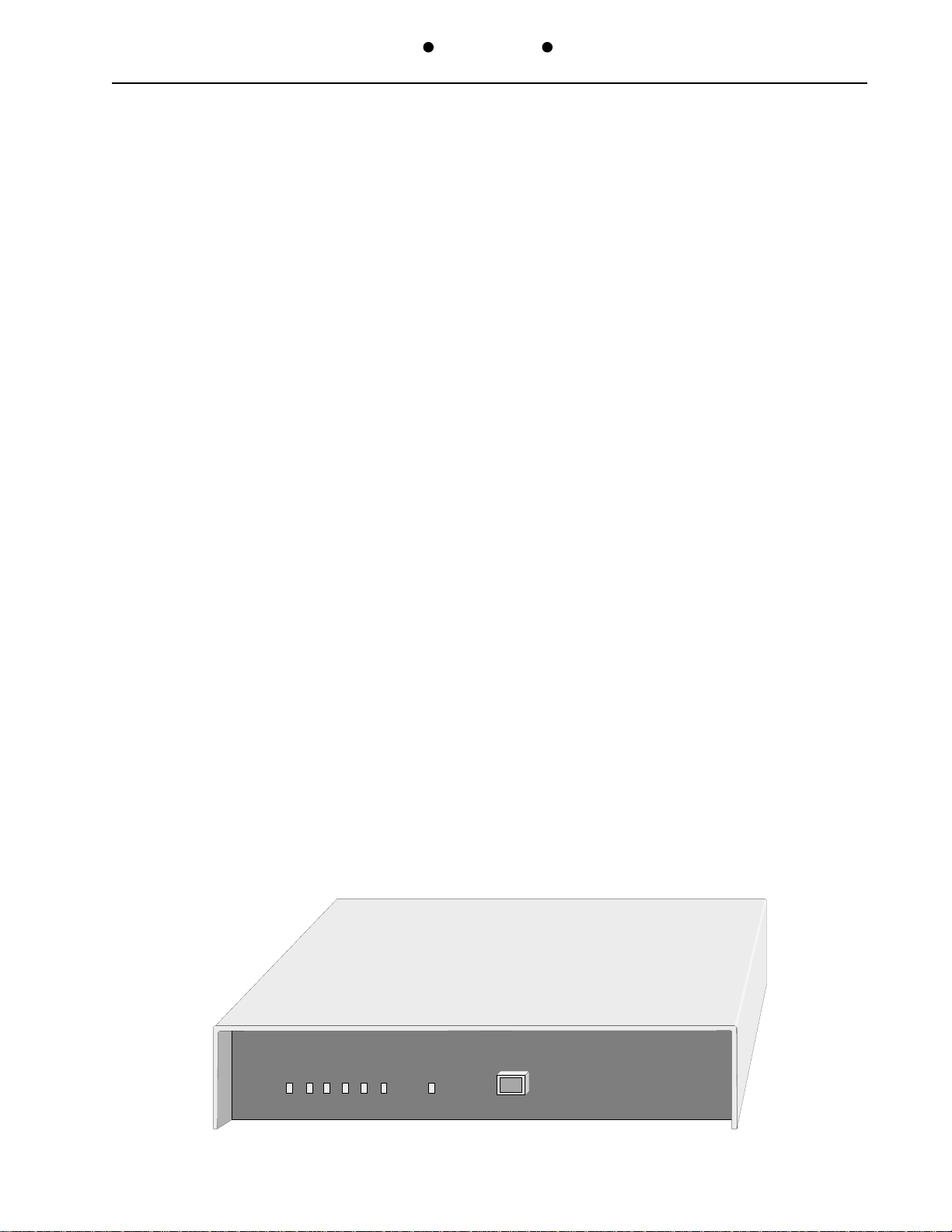
Front Panel
The power indicator, marked PW on the front panel is green and indicates when AC voltage
is applied to the unit. The two adjacent green LED indicators illuminate in conjunction with
Send Data (SD) and Receive Data (RD). Request to Send (RS), Clear to Send (CS),
Carrier Detect (CD) and Anti-Stream (AS) status LED’s are also provided to give a clear
visual indication of the 1084’s (CTS LD-128K) operational status. The Digital Loop Back
switch provides a convient means to verify operation of the data communication circuit.
When the button is not depressed (BLACK), the 1084 (CTS LD-128K) operates normally,
providing communication from end to end. When in (YELLOW), the 1084 (CTS LD-128K)
provides bilateral looping to facilitate testing of the line driver and communication circuit
from either end.
Point to Point / Multi-Point Operation
The 1084 (CTS LD-128K) utilizes RS-485 tristate drivers and receivers. Both Switched
Carrier and Constant Carrier operation are possible. When Switched Carrier is selected, up
to 32, 1084 devices may be connected together to form a Multi-Drop network. Distance from
the master 1084 to the last 1084 in the network are dependent on data rate selected and the
gauge of wire used to connect the units. The higher the data rate and thinner the gauge of
wire used, the shorter the communication distance possible. During Constant Carrier
operation, the 1084’s are connected in a point to point configuration. As with Multi-point
operation, the higher the data rate and thinner the gauge of wire used, the shorter the
communication distance possible. The 1084 can also be used point to point in the switched
carrier mode.
1084
PW TD RD RS CS CD AS DIGITAL
LOOPBACK
1-1
Operation
Page 6

PATTON ELECTRONICS CO. 1084 INSTALLATION AND OPERATIONS MANUAL
141001UA
“Switch on Data” Mode
To allow terminals that do not respond to RS and CS control leads to operate in a MultiPoint or Point to Point network, the “Switch on Data” mode has been provided. When a
terminal sends data transitions, the 1084 (CTS LD-128K) will bring up its carrier and start to
transmit. When the data transitions stop for a period greater than the selected “No Data
Time-out” the carrier will drop and the 1084 (CTS LD-128K) will return to an idle state. CS
is constant when in “Switch on Data” Mode.
Clocking
Rates up to 128Kbps are internally generated by the 1084 (CTS LD-128K) for Transmit
clocking. Clocking may also be taken from an external device on the External Transmit
Clock Lead, pin 24, to facilitate tail circuit applications. To ensure synchronization of clock
through a system, Receive clock may also be utilized as the Transmit clocking source
(slave clocking).
Four Wire / Two Wire Operation
Half duplex 2 wire operation as well as 4 wire full duplex operation is selectable via
configuration switches.
Testing Modes
Local digital loop-back is easily selected via a front panel mounted switch. A positive visual
indication is provided when the 1084 (CTS LD-128K) is in loop-back mode. The data line is
looped bilaterally to allow both the local terminal and the remote terminal to be tested when
in 4 wire mode.
CTS Delays
CTS can be configured to respond to RTS regardless of the state of the transmitter. RTS to
CTS delays can be set to constant, 0mS, 8mS or 50mS.
Anti-Streaming
When a terminal in a Multi-drop network fails, with the RS signal lead active, the attached
LD-128K will remain transmitting. This “Streaming” terminal will cause the entire network to
fail. To prevent this type of failure, the 1084 (CTS LD-128K) provides Anti-Streaming
protection. When Anti-Sreaming is enabled, the control logic will turn off the 1084’s (CTS
LD-128K) transmitter after seeing an RS signal for the selected period of time. The
transmitter will not turn on again until the RS signal is released by the terminal.
Operation
1-2
Page 7

NSTALLATION AND OPERATIONS MANUAL1084PATTON ELECTRONICS CO.
I
141001UA
Caution, Disconnect the POWER Before Removing The Cover.
Vorsicht, Befor Deckung Abnehmen Mach Strom Zu.
CHAPTER 2 - SETUP AND INSTALLATION
Power Connection
Before connecting the 1084 (CTS LD128K) to a AC power source the top cover
must be installed and secured with the
supplied #4-32 screws. The unit is
supplied with a 110/220V voltage switch,
turn the switch with a coin or screw driver
110
220
100-120V
0.16ASB,250V
TO.16A,250V
200-240V
0.08ASB,250V
TO 0.08A,250V
110 / 220V Switch
Fuse Drawer
CAUTION
FIRE, REPLACE ONLY WITH SAME TYPE AND RATING FUSE.
: FOR CONTINUED PROTECTION AGAINST RISK
PORT 1
IEC Power Connector
to the appropriate voltage for your
country. If the unit is set to 110V insure that the fuses are 0.16A Slow Blow (Little Fuse
218.160). For 220V operation use 0.08A (Little Fuse 218.080) Slow Blow fuses.
EXAMPLE: United States of America; set to 110V. The unit is supplied with a IEC power
connector next to the voltage select switch, plug the power cord into the connector until it is
firmly seated. You may now connect the power cord into your AC outlet.
Factory Configuration Switch Settings
The 1084 (CTS LD-128K) is configured prior to shipment with the switches set to the
following default positions:
Switch 1 - 2 and 5 to
OFFOFF
OFF, 1, 3, 4 and 6 to
OFFOFF
ONON
ON
ONON
Baud rate 64K
CS Delay 0 mS
NN
MM
Switch 2 - 1, 2 and 6
OFFOFF
OFF, 3, 4 and 5 to
OFFOFF
ONON
ON
ONON
Switch on RS
Full Duplex
Anti-Stream Disabled
Signal Ground not connected to Chassis Ground
Switch 4 - 1, 3, 5 and 6 to
OFFOFF
OFF, 2 and 4 to
OFFOFF
ONON
ON
ONON
Constant Carrier
TX Clock From Internal
Sync Operation
Receiver Termination OUT
Jumpers - J1, J2 & J3
ININ
IN, J4 & J5
ININ
OUTOUT
OUT
OUTOUT
Factory test jumpers J1-J3 Must be in for proper operation.
4 Wire Operation
2-1
Setup & Installation
Page 8

ATTON ELECTRONICS CO. 1084 INSTALLATION AND OPERATIONS MANUAL
P
141001UA
If the system application requires one or more of the default settings to be changed, it will be
necessary to remove the top cover of the enclosure to access and change the DIP switches
located on the printed circuit board.
Disassembly
U
NPLUG THE POWER CORD BEFORE PROCEEDING
then remove the top cover by unscrewing the
phillips head screws located on the left and right sides of the unit. The configuration
switches and jumpers are located on the Printed Circuit Board (PCB) as indicated on the
appropriate strapping guide in the Appendix of this manual. After the switch selection
activity is completed,
S
OURCE
.
R
EINSTALL THE TOP COVER
BEFORE C
ONNECTING TO AN
AC P
OWER
Installation
Select an appropriate location, accessible to and within six feet of an AC power outlet. Use
a “Straight Through”, shielded cable, between the attached terminal device and the 1084
(CTS LD-128K) (
The 1084 has a female DB-25 Connector
). Connect the RS-232 terminal
device to the connector marked J4. The 1084’s (CTS LD-128K) are connected using a
standard, crossed, RJ45 telephone cable. Plug the cable into connector J2 or J3, which are
in parallel with each other, to allow connection of multiple 1084’s (CTS LD-128K) for MultiPoint operation. Standard Telephone cords can be used provided the wire pairs are
reversed.
Caution: Never connect the RJ-45 Line connectors to
the Public Switched Telephone Network!
Equipment Grounding (SW2-6)
SW2 Position 6 provides for grounding interconnection in those systems requiring a
connection between (Frame Ground) and (Signal Ground).
Set to
Point to Point / Multi-Drop Connectors J2 & J3
J2 and J3 are parrallel RJ-45 connectors. Pin 1 on J2 is connected to pin 1 on J3, pin 2 on
J2 is connected to pin 2 on J3 and likewise for the remainder of the pins. This allows two
1084 (CTS LD-128K) to be connected by simply installing a standard crossed telephone
cable between the units. When adding addtional units for a Multi-Drop application, chain
the J2 or J3 from one unit to another, using a standard straight through telephone cable. It is
not important which connector is used, as J2 and J3 are electrically eqivalant to each other.
All of the Slave 1084 (CTS LD-128K) receivers (pins 7&8), must be tied together and
connected to the transmitter of the Master 1084 (CTS LD-128K) and all of the Slave LD128K transmitters (pins 1&2), must be tied together and connected to the receiver of the
Master 1084 (CTS LD-128K). (see Appendix)
ONON
ON
, ONLY if required
ONON
.
Setup & Installation
2-2
Page 9

Full / Half Duplex Selection (SW2-2)
NSTALLATION AND OPERATIONS MANUAL1084PATTON ELECTRONICS CO.
I
141001UA
SW2 position 2 selects Full or Half Duplex Line Driver operation. When SW2-2 is
OFFOFF
OFF the
OFFOFF
1084 (CTS LD-128K) will operate in Full Duplex mode. When SW2-2 is ON the 1084 (CTS
LD-128K) will operate in Half Duplex mode.
Two Wire / Four Wire (JP4 & JP5)
Half Duplex, 2 Wire Operation, install Jumpers JP4 and JP5. This will connect the input
pins to the output pins, 2 to 7 and 1 to 8. To operate in 4 Wire mode, remove the jumpers.
(see Appendix)
Baud Rate Selection (SW1-1,2,3,4)
Baud rates are selected via SW1 positions 1 through 4. The following Table outlines the
available speeds and corresponding switch setting. The selected baud rate will take effect
immediately upon moving the switch. It is not necessary to power cycle the 1084 (CTS LD128K) for any switch selection to go into effect.
SW1-1 SW1-2 SW1-3 SW1-4
ON ON ON ON 128K
OFF ON ON ON 72K
Rate
ON OFF ON ON 64K
OFF OFF ON ON 56K
ON ON OFF ON 48K
OFF ON OFF ON 38.4K
ON OFF OFF ON 28.8K
OFF OFF OFF ON 19.2K
ON ON ON OFF 14.4K
OFF ON ON OFF 9.6K
ON OFF ON OFF 7.2K
OFF OFF ON OFF 4.8K
ON ON OFF OFF 3.6K
OFF ON OFF OFF 2.4K
ON OFF OFF OFF 1.8K
OFF OFF OFF OFF 1.2K
2-3
Setup & Installation
Page 10

ATTON ELECTRONICS CO. 1084 INSTALLATION AND OPERATIONS MANUAL
P
141001UA
“Switch on RS” or “Switch on Data” Mode (SW2-1)
SW2 position 1 determines the action required to turn the carrier on and off. When SW2-1 is
OFFOFF
OFF, carrier is turned on whenever the RS (pin4) interface lead is active. Carrier is removed
OFFOFF
whenever the RS interface lead is inactive. Setting SW2-1 to
ONON
ON will select “Switch On
ONON
Data” mode. Whenever data transitions are present on the TD (pin2) interface lead, the
carrier will be activated.
CTS Delay Selection When “Switch on RS” is Enabled (SW1-5,6)
SW1-5 and 6 determine the RS to CS (pin5) delay when SW2-1 is
SW1-5 SW1-6
ON ON Constant
OFF ON Delayed 0 mS
ON OFF Delayed 8 mS
OFF OFF Delayed 50 mS
CS Operation
OFFOFF
OFF.
OFFOFF
Carrier Control (SW4-1)
SW4 position 1 determines Constant Carrier or Switched Carrier operation. Set SW4-1 to
OFFOFF
OFF if “Point to Point” continuous full duplex operation is desired. Set SW4-1 to
OFFOFF
ONON
ON if
ONON
“Multipoint” or Half Duplex Operation is desired.
Receiver Termination (SW4-5)
Termination of the Master 1084 (CTS LD-128K) and the farthest 1084 (CTS LD-128K) in a
“Multipoint” network is provided by setting SW4-5 to ON. Only the farthest 1084 (CTS LD128K) of the multiple slave 1084’s (CTS LD-128K) in the network should have the
termination Enabled. In “Point to Point” applications, termination should be Enabled on
both 1084’s (CTS LD-128K).
Transmit Clock Source (SW4-2,3)
SW4 positions 2 and 3 determine the source of the transmit clock. The following table
outlines the available options.
SW4-2 SW4-2
X ON SLave From RXC
ON OFF Internal
OFF OFF External (pin24)
Setup & Installation
TX Clock Source
2-4
Page 11

NSTALLATION AND OPERATIONS MANUAL1084PATTON ELECTRONICS CO.
I
Sync or Async Operation (SW4-4)
SW4 position 4 configures the 1084 (CTS LD-128K) for Synchronous or Asynchronous
operation. Set SW5-4 to
ONON
ON if Synchronous operation is required and
ONON
OFFOFF
OFF if Asynchronous
OFFOFF
operation is required.
Anti-Streaming (SW2-3,4,5)
141001UA
Anti-Streaming protection is provided via SW2 position 3 through 5. SW2-3, 4, and 5
ONON
ON
ONON
will Disable Anti-Streaming. When Anti-Streaming is enabled, SW2-3, 4 and 5 determine
the number of bits of continuous data (
Switch on Data
mode) or RS (
Switch on RS
mode)
that indicates the terminal connected to the 1084 (CTS LD-128K) is in a streaming
condition. The following table gives the selections available for streaming cutoff.
SW2-3 SW2-4 SW2-5
ON ON ON Disabled
OFF ON ON 1024
ON OFF ON 2048
OFF OFF ON 4096
ON ON OFF 16K
OFF ON OFF 64K
ON OFF OFF 256K
OFF OFF OFF 1M
Anti-Stream Timer
Factory Straps (JP1,JP2,JP3)
JP1, JP2 and JP3 are used for testing the 1084 (CTS LD-128K) during production. These
jumpers must be installed for the unit to function properly.
2-5
Setup & Installation
Page 12

PATTON ELECTRONICS CO. 1084 INSTALLATION AND OPERATIONS MANUAL
APPENDIX
TECHNICAL SPECIFICATIONS
141001UA
Application
Full or Half Duplex, Sync or Async. Point to
Point or Multi-Point
Data Format
Data is Transparent
Data Rates
1.2Kbps to 128Kbps
Driving Distance
4000ft up to 128Kbps
Timing
Internal Baud Rate Generator
Receiver Slave
External (pin 24)
Channel Interface
Front Panel
Indicators: . Power, TD, RD, RS, CS, CD &
AS
Switches:... Digital Loop Back
Power Source
100-120/200-240VAC, 50 to 60Hz, 0.16/
0.08A switchable
Environmental
Oper Temp: .... 32° to 122°F (0° to 50°C)
Rel Humidity: .. 5 to 90% non-condensing
Altitude:........... 0 to 10,000 feet
Protection
Both Common Mode (Longitudinal) and
Differential (Metallic) surge suppressors are
provided on the line transmit output and
receive input connections.
EIA RS-232 (V.24) female connector (DB-
25)
Line Requirements
Two or Four Wire private line: Unloaded
with no bridge taps.
Line Interface
RJ-45 Plug, RS-485 Electrical
Specification
Dimensions
Height:..... 1.75 inches (4.44 cm)
Width:...... 8.90 inches (22.60 cm)
Length:.... 10.00 inches (25.40 cm)
Warranty
Two Years, Return to Factory
A-1
Appendix
Page 13

141001UA
g
PATTON ELECTRONICS CO. 1084 INSTALLATION AND OPERATIONS MANUAL
External Transmit Clock (from DTE)
Receive Clock (from DCE)
Transmit Clock (from DCE)
RS-232
25
24
23
22
21
20
19
18
17
16
15
14
RS-232 Pin Out
Two or Four
Wire Unload e d
Private Line
13
12
11
10
9
Data Carrier Detect (from DCE)
8
Si
nal Ground (common)
7
Data Set Ready (from DCE)
6
5
Clear To Send (from DCE)
Request to Send (from DTE)
4
Receive Data (from DCE)
3
Transmit Data (from DTE)
2
Shield (common)
1
RS-232
Appendix
A
110
220
100-120V
0.16ASB,250V
TO.16A,250V
200-240V
0.08ASB,250V
TO 0.08A,250V
International
RSRXTXPW
Loop back
Digital
RCTCCDCS
Series
1084
A
Digital
RCTCCDCS
RSRXTXPW
Loop back
International
Series
1084
Application Diagram
CAUTION: FOR CONTINUED PROTECTION AGAINST RISK OF
FIRE, REPLACE ONLY
WITH SAME TYPE
AND RATING FUSE.
PORT 1
J2 J3
J4
Rear Panel View
A-2
Page 14

PATTON ELECTRONICS CO. 1084 INSTALLATION AND OPERATIONS MANUAL
141001UA
J2 & J3
12345678
TX RX
1084 #1
12 78 1 2 78
Four Wire Hookup “Point to Point”
1084 #1
JP5 JP4
12 78
Two Wire Hookup “Point to Point”
1084 #2
1084 #2
JP5 JP4
12 78
Master Slave Slave
1084 #21084 #1 1084 #3
J2 J2 J2J3
12 78 1 2 78 12 78 12 78
Four Wire Hookup “Multi-Point”
Mast er
1084 #1
JP5 JP4
12 78
Sla ve
1084 #2
JP5 JP4
12 78
12 78
Sla ve
1084 #3
JP5 JP4
12 78
Two Wire Hookup “Multi-Point”
A-3
Appendix
Page 15

Appendix
141001UA
A-4
Power
TD
RD
RS
5
ON
OFF
ON
OFF
CTS Delay - SW1
6
Function
ON
CTS Contant
ON
CTS Delayed 0 mS
OFF
OFF
CTS Delayed 8 mS
CTS Delayed 50 Ms
CS
CD
Anti-Stream
SW1
ONOFF
SW2
ONOFF
123456
Baud Rate Select
CTS Delay
123456
Switch on RTS=OFF / Data=ON
Half=ON / Full=OFF Duplex
Anti-Stream Timer
Sig to Chas Gnd Connected=ON
TX Clock Source - SW4
2
X
ON
OFF
SW4
ONOFF
JP1
Loopback
+5V +8V -8V
YELLOW=Looped, BLACK=Normal
CTS Delay
SW2-1 OFF
Source
3
Slave From RXC
ON
Internal TXC
OFF
External (pin24)
OFF
123456
Const=OFF / Switched=ON Carrier
TX Clock Source
Sync=ON / Async=OFF
Rcvr Term In=ON / Out=OFF
Not Used
JP2
JP3
Baud Rate Select - SW1
4
3
2
1
ON
ON
ON
ON
OFF
ON
OFF
ON
OFF
ON
OFF
ON
OFF
ON
OFF
ON
OFF
ON
OFF
ON
OFF
OFF
ON
ON
OFF
OFF
ON
ON
OFF
OFF
ON
ON
OFF
OFF
OFF
OFF
OFF
OFF
ON.
ON.
OFF
OFF
OFF
OFF
ON
ON
ON
ON
ON
ON
ON
ON
ON
ON
ON
ON
OFF
OFF
OFF
OFF
OFF
OFF
OFF
OFF
Anti-Stream Timer - SW2
3
ON
OFF
ON
OFF
ON
OFF
ON
OFF
4
ON
ON
OFF
OFF
ON
ON
OFF
OFF
5
ON
ON
ON
ON
OFF
OFF
OFF
OFF
Count
Disabled
1024
2048
4096
16K
64K
256K
1M
Rate
128K
72K
64K
56K
48K
38.4K
28.8K
19.2K
14.4K
9.6K
7.2K
4.8K
3.6K
2.4K
1.8K
1.2K
Connecto r
RS-232
J4
PATTON ELECTRONICS CO. 1084 INSTALLATION AND OPERATIONS MANUAL
J3 J2
Connecto r s
Wire Line
Instal l Jumpers for 2 Wire Operation
Remove for 4 Wire Operation
JP4
JP5
Green/Yellow
4
Blue
3
Brown
2
Brown
1
J1
Page 16

B
7622 Rickenbacker Drive
Gaithersburg, MD 20879
Sales: 301 975-1000 Support: 301 975-1007
Web Address: www.patton.com
 Loading...