

Page 1
USER
MANUAL
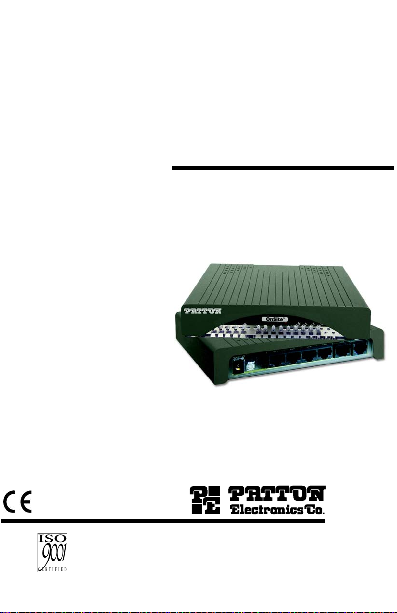
MODEL 1069
OnSite™ VDSL2 CPE
REGULATORY MODEL NUMBER:
03342D4-001
This is a Class A device and is not intended for
use in a residential environment.
Part# 07M1069-UM
Rev. A
Revised 12/21/11
An ISO-9001Certified
Company
SALES OFFICE
(301) 975-1000
TECHNICAL SUPPORT
(301) 975-1007
Page 2

CONTENTS
1.0 Warranty Information ................................................................. 3
1.1 Regulatory Information ................................................................. 3
EMC Directive:............................... ...... ..... .................................... 3
Low-Voltage Direcive (Safety):..................................................... 3
PSTN:.................................................. ..... .................................... 3
1.2 Radio and TV Interference (FCC Part 15) .................................... 3
1.3 CE Declaration of Conformity ....................................................... 4
1.4 Authorized European Representative........................................... 4
1.5 Service.......................................................................................... 4
1.6 Safety When Working With Electricity .......................................... 5
2.0 General Information.................................................................... 7
2.1 Features........................................................................................ 7
2.2 Description.................................................................................... 7
2.3 Application.................................................................................... 8
3.0 Installation................................................................................... 9
3.1 Connecting the Line Interface..................................................... 10
3.2 Connecting the 10/100Base-T Ethernet Interface ...................... 11
3.3 Connecting the POTS/ISDN Line ............................................... 11
3.4 Connecting Power ............................... ..... .................................. 12
4.0 Configuration ............................................................................ 12
5.0 Operation................................................................................... 13
5.1 Front Panel LED Status Monitors ............................................... 13
A
Specifications ........................................................................... 14
A.1 VDSL2 ......................................................................................... 14
A.2 LAN Connection ......................................................................... 14
A.3 Transmission Line ....................................................................... 14
A.4 LED Status Indicators ................................................................. 14
A.5 Power Supply .............................................................................. 14
A.6 Temperature Range .................................................................... 14
A.7 Humidity ...................................................................................... 14
A.8 Dimensions ................................................................................. 14
B
Model 1069 Series Factory
Replacement Parts and Accessories ...................................... 15
C
Model 1069 Series Interface Pin Assignment ........................ 16
C.1 10/100Base-T Interface .............................................................. 16
RJ-45.......................................................................................... 16
C.2 VDSL2 Interface .......................................................................... 16
RJ-45.......................................................................................... 16
C.3 POTS/ISDN Interface .................................................................. 16
RJ-45.......................................................................................... 16
2
Page 3

1.0 WARRANTY INFORMATION
Patton Electronics warrants all Model 1069 comp onent s to be free fro m
defects, and will—at our option—repair or replace the product should it
fail within one year from the first date of the shipment.
This warranty is limited to de fects in workmansh ip or materials, a nd does
not cover customer damage, abuse or unauthorized modification. If this
product fails or do es not perfo rms as warrante d, you r so le reco urse shal l
be repair or replacement as described above. Under no condition shall
Patton Electronics be liable for any damages incurred by the use of this
product. These dama ges include , but are not limite d to, the follow ing: lost
profits, lost savings and incidental or consequential damages arising
from the use of or inability to use this product. Patton Electronics spe-
cifically disclaims all other warranties, expressed or implied, and the
installation or use of this product shall be deemed an acceptance of
these terms by the user.
Note Conformity documents of all Patton products can be viewed
online at www.patton.com under the appropriate product page.
1.1 REGULATORY INFORMATION
EMC Directive:
• FCC Part 15, Class A
• EN55022, Class A
• EN55024
Low-Voltage Direcive (Safety):
• IEC/EN60950-1, 2nd Edition
• AS/NZS 60950-1
PSTN:
• This device is not intended nor approved for connection to the PSTN
1.2 RADIO AND TV INTER FERENCE (FCC PART 15)
This device generates and uses radio frequency energy, and if not
installed and used pro perly- that is, in stric t acco rdance with the m anufa cturer’s instructions-may cause interference to radio and television reception. The devi ce h as b een tes ted a nd fo und t o comp ly wi th the l imit s for a
Class A computing devi ce i n acc ordanc e with spec ificat ions in Su bpa rt B
3
Page 4

of Part 15 of FCC rules, which are designed to provide reasonable protection from such interference in a commercial installation. However,
there is no guaran tee tha t interference will not occur in a p articular installation. If the device does cause interference to radio or television reception, which can be determined by disconnecting the unit, the user is
encouraged to try to cor rect the in terferen ce by one o r more of t he foll owing measures: mov ing the computing equipment away from the rec eiver,
re-orienting the receiving antenna and/or plugging the receiving equipment into a different AC outlet (such that the computing equipment and
receiver are on different branches).
1.3 CE DECLARATION OF CONFORMITY
Patton Electronics, Inc decl ares tha t this devic e is in c ompli ance wi th th e
essential requirements and other relevant provisions of Directive
2004/108/EC relating to electromagnetic compatibility and Directive
2006/95/EC relating to electrical equipment designed for use within certain voltage limits. The Declaration of Conformity may be obtained from
Patton Electronics, Inc at www.patton.com/certifications.
The safety advice in the documentation accompanying this device shall
be obeyed. The conformity to the above directive is indicated by CE
mark on the device.
1.4 AUTHORIZED EUROPEAN REPRESENTATIVE
D R M Green
European Compliance Services Limited.
Avalon House, Marcham Road
Abingdon, Oxon OX14 1U D, UK
1.5 SERVICE
All warranty and non-wa rranty repairs must be returned freight prepaid
and insured to Patton Electro nic s. All retu rns mus t hav e a Ret urn M ate rials Authorization number on the outside of the shipping container. This
number may be obtained from Patton Electronics Technical Services at:
•Tel: +1 (301) 975-1007
•Email: support@patton.com
• URL: http://www.patton.com
Note Packages received without an RMA number will not be
accepted.
4
Page 5

1.6 SAFETY WHEN WORKING WITH ELECTRICITY
• This device contains no user serviceable parts. This
device can only be repaired by qualified service personnel.
• Do not open the device when the power cord is connected. For systems without a power switch and without
an external power adapter, line voltages are present
within the device when the power cord is connected.
• For devices with an external power adapter, the power
adapter shall be a listed Limited Power Source. The
mains outlet that is utilized to power the device shall be
within 10 feet (3 meters) of the device, shall be easily
accessible, and protected by a circuit breaker in compliance with local regulatory requirements.
• For AC powered devices, ensure that the power cable
used meets all applicable standards for the country in
which it is to be installed.
• For AC powered devices which have 3 conductor
power plugs (L1, L2 & GND or Hot, Neutral &
WARNING
Safety/Protective Ground), the wall outlet (or socket)
must have an earth ground.
• For DC powered devices, ensure that the interconnecting cables are rated for proper voltage, current, anticipated temperature, flammability, and mechanical
serviceability.
• WAN, LAN & PSTN ports (connections) may have hazardous voltages present regardless of whether the
device is powered ON or OFF. PSTN relates to interfaces such as telephone lines, FXS, FXO, DSL, xDSL,
T1, E1, ISDN, Voice, etc. These are known as “hazardous network voltages” and to avoid electric shock use
caution when working near these ports. When disconnecting cables for these ports, detach the far end connection first.
• Do not work on the device or connect or disconnect
cables during periods of lightning activity.
5
Page 6

WARNING
WARNING
In accordance with the requirements of council directive 2002/96/EC on Waste of Electrical and Electronic
Equipment (WEEE), ensure that at end-of-life you separate this product from other waste and scrap and deliver
to the WEEE collection system in your country for recycling.
This device contains no user serviceable parts. This
device can only be repaired by qualified service personnel.
This device is NOT intended nor approved for connection to the PSTN. It is intended only for connection to
customer premise equipment.
Electrostatic Discharge (ESD) can damage equipment
and impair electrical circuitry. It occurs when electronic
printed circuit cards are improperly handled and can
result in complete or intermittent failures. Do the following to prevent ESD:
WARNING
• Always follow ESD prevention procedures when
removing and replacing cards.
• Wear an ESD-preventive wrist strap, ensuring that it
makes good skin contact. Connect the clip to an
unpainted surface of the chassis frame to safely channel unwanted ESD voltages to ground.
• To properly guard against ESD damage and shocks,
the wrist strap and cord must operate effectively. If no
wrist strap is available, ground yourself by touching the
metal part of the chassis.
6
Page 7

2.0 GENERAL INFORMATION
Thank you for your purchase of this Patton Electronics product. This
product has been thoroughly inspected and tested and is warranted for
one year for parts and labor. If any questions or problems arise during
installation or use of this product, contact Patton Electronics Technical
Support at +1 (301) 975-1007.
2.1 FEATURES
• VDSL2 - Easy to configure
• Auto-MDIX Ethernet
• Configurable 10/100, Full/Half, and Auto-Negotiating Ethernet
• Extends up to 4x 10/100Base-TX Ethernet beyond 328-foot (100-
meter) limitation over a single twisted-pair or Cat5+
• Symmetric or asymmetric settings
• POTS/ISDN splitter on board
• Transparent oper ation
• LED indicators for Power, DSL Link, Ethernet Link/Activity, Remote and
Local
2.2 DESCRIPTION
The Patton Electronics Model 1069 OnSite CPE provides high-speed
VDSL2 connections to any standards-based VDSL2 DSLAM.
The Model 1069 can automatically forward LAN broadcasts , multica st s,
and frames across a 2-wire voice-grade twisted-pair link. The data is
passed transparently (unmodified) through the 1069. The 1069 automatically adds and deletes MAC addresses, only pas sing p ac ket s ac ross the
VDSL2 link.
Figure 1 on page 8 describes the rear panel ports on the Model 1069
VDSL CPE.
7
Page 8

POTS/ISDN
3
th
E
2
th
E
1
th
E
0
th
E
A
1
C
D
V
2
1
Ethernet ports
(0-3)
POTS/ISDN twisted-pair
RJ-45 interface
VDSL twisted-pair
RJ-45 interface
Reset switch
Powe r jack
Figure 1. Model 1069 rear panel
2.3 APPLICATION
In an example application, the VDSL2 CPE modem is placed in either
MxU environments or individual residents for delivering triple play services including “fiber like” high-speed broadband service. Built-in
POTS/ISDN splitters all ow for both dat a and voice t o be broken out at the
CPE.
Figure 2. Model 1069 and VDSL DSLAM application
8
Page 9

3.0 INSTALLATION
The Interconnecting cables shall be acceptable for
external use and shall be rated for the proper application with respect to voltage, current, anticipated tem-
CAUTION
perature, flammability, and mechanical serviceability.
To connect the Model 1069, do the following:
1. Connect the Line port of the Model 1069 with a telephone cable
(refer to section 3.1, “Connecting the Line Interface” on page 10).
2. Connect an Ethernet port to the network card of a PC via an Ether-
net cable (refer to sectio n 3.2 , “Conn ec tin g the 10/100Base-T Ethernet Interface” on page 11).
3. Connect the Power plug to the wall outlet (refer to section 3.4, “Co n-
necting Po wer” on page 12).
Figure 3 displays the connections of the unit to a PC, telephones, DSL
outlet, and power outlet.
POTS/ISDNLineEth0 Eth1 Eth2 Eth3Power
Figure 3. Model 1069 connection diagram
9
Page 10

3.1 CONNECTING THE LINE INTERFACE
The Interconnecting cables shall be acceptable for
external use and shall be rated for the proper application with respect to voltage, current, anticipated tem-
CAUTION
perature, flammability, and mechanical serviceability.
The Model 1069 suppo rts commu nication over a di stance of up to 10,000
ft (3 km) over 24 AWG (0.5 mm) twisted-pair wire or Cat5+.
Note Actual distance and link performance may vary depending on
the environment and type/gauge of wire used.
Follow the steps below to connect the Model 1069 interfaces.
1. To function properly, the Model 1069 must be connected with the
VDSL2 DSLAM using twisted-pair, unconditioned, dry, metal wire,
between 19 (0.9mm) and 26 A WG (0.4m m). Leas ed cir cuit s that run
through signal equalization equipment are not acceptable.
2. The Model 1069 is equipped with an RJ-45 interface jack that can be
used on the VDSL2 link interface. The VDSL2 link interface is a twowire interface. Observe the signal/pin relationships on the Model
1069's VDSL2 interface jack.
The RJ-45 connector on the Model 1069's twisted pair interface is polarity insensitive and is wired for a two-wire interface. The signal/pin relationship is shown in Figure 4.
1 (no connection)
1
2
3
4
5
6
7
8
2 (no connection)
3 (no connection)
4 (RING)
5 (TIP)
6 (no connection)
7 (no connection)
8 (no connection)
Figure 4. Model 1069 (RJ-45) twisted pair line interface.
10
Page 11

3.2 CONNECTING THE 10/100BASE-T ETHERNET INTERFACE
(
)
The Interconnecting cables shall be acceptable for
external use and shall be rated for the proper application with respect to voltage, current, anticipated tem-
CAUTION
perature, flammability, and mechanical serviceability.
The RJ-45 ports labe le d Ethernet are the Auto-MDIX10/100Base-T inter-
face. These ports are designed to connect directly to a 10/100Base-T
device or network. Figure 5 shows the signal/pin relationships on this
interface. You may connect this port to a hub or PC using a straight
through or crossover cable that is up to 328 ft long.
1 TX+/RX+
1
2
3
4
5
6
7
8
Figure 5. Model 1069 10/100Base-T RJ-45 Connector Pinout.
2 TX-/RX-
3 RX+/TX+
4 (no connection)
5 (no connection)
6 RX-/TX-
7 (no connection)
no connection
8
3.3 CONNECTING THE POTS/ISDN LINE
The RJ-45 port labeled “POTS/ISDN” is the POTS/ISDN interface. A
telephone or an ISDN device may be connected to this port and carried
over the VDSL2 line. The unit s do no t need powe r for the POTS interfac e
to work. The RJ-45 connector in the Mode l 1069’s POTS/ISDN interface
is wired as shown in Figure 7.
1 (no connection)
1
2
3
4
5
6
7
8
Figure 6. Model 1069 (RJ-45) POTS/ISDN interface.
2 (no connection)
3 (no connection)
4 (2-wire RING)
5 (2-wire TIP)
6 (no connection)
7 (no connection)
8 (no connection)
11
Page 12

3.4 CONNECTING POWER
The Interconnecting cables shall be acceptable for
external use and shall be rated for the proper application with respect to voltage, current, anticipated tem-
CAUTION
The Model 1069 does not have a power switch, so it powers up as soon
as it is plugged in.
An external AC or DC power supply is availab le se p ar atel y. This connection is made via the barrel jack on the rear panel of the Model 1069. No
configuration is necessary for the power supply (See Appendix B for
domestic and international power supply and cord options).
DC power (supplied via the power supply jack to the 1069) must meet
the following requirements; DC power supplied must be regulated
12VDC ±5%, 1.0A minimum. Center pin is +12V. The barrel type plug
has a 2.5/5.5/10mm I.D./O.D./Shaft Length dimensions.
All configurations for the Model 1069 VDSL2 CPE should be made
through the VDSL2+ DSLAM. The dipswitch included in the Model 1069
is for factory use only.
perature, flammability, and mechanical serviceability.
4.0 CONFIGURATION
12
Page 13

5.0 OPERATION
Once the Model 1069 is properly installed, it should operate transparently. No user settings required. This section de scribes reading the LED
status monit ors.
Before applying power to the Model 1069, please review section 3.4,
“Connecting Power” on p age 12 to verify that the unit is conne cted to the
appropriate power source.
5.1 FRONT PANEL LED STATUS MONITORS
The Model 1069 features six front panel LEDs that monitor power, the
Ethernet signals, the VDSL2 connection, and the remote/local setting.
Figure 7 shows the front panel location of each LED . Table 1 on page 13
describes t he LED functions.
™
Ethernet Link
Remote Unit
Local Unit
DSL Link
Power
Figure 7. Model 1069 front panel
Tab le 1: Front panel LED description
LED Status Description
Power Green The device is powered o n.
Off The device is powered o ff.
OnSite Green The port is connected.
Blinking Green Data transceiving.
Off No valid link on this port.
Ethernet Green The port is connected.
*
Blinking Green
Data transceiving.
Local Green The device acts in Local mode.
Off Local mode is off.
Remote Green The device acts in Remote mode.
Off Remote mode is off.
*.
Once the unit connects to a power sourc e, the Link LED will
blink as the 1069 automatically looks for the other unit.
13
Page 14

APPENDIX A
SPECIFICATIONS
A.1 VDSL2
• Full compliance up to 30Mhz profile
A.2 LAN CONNECTION
• Four RJ-45, 10/100Base-T, IEEE 802.3 Ethernet
A.3 TRANSMISSION LINE
• Two-wire unconditioned twis ted pair
• VDSL2 Connector: RJ-45
A.4 LED STATUS INDICATORS
• Power (Green)
• VDSL2: Link (Green)
• Local (Green)
• Remote (Green)
• Ethernet: Link (Green) & Activity (Flashing Green)
A.5 POWER SUPPLY
External AC and DC options:
• AC: 120 VAC, 220 VAC, and UI (120–240 VAC)
• DC: 12 VDC, 24 VDC and 48 VDC
• Power consumption: 400mA at 12VDC
A.6 TEMPERATURE RANGE
0–50°C
A.7 HUMIDITY
Up to 90% non-condensing.
A.8 DIMENSIONS
6.22 W x 1.25 H x 4.75 D in. (157 W x 318 H x 120 D mm)
14
Page 15

APPENDIX B
MODEL 1069 SERIES FACTORY
REPLACEMENT PARTS AND ACCESSORIES
Patton Model # Description
Base Models
1069/EUI OnSite VDSL2 CPE
RJ45 Line, 100-240VAC
07M1069-UM User Manual
Power Supplies
PS-03671H1-002 100-240VAC (12V, DC/2A) Wall mount power adapter
Power Adapters
12-130 European replacement plug
12-129 American replacement plug
12-131 United Kingdom plug
12-132 Australian/Chinese plug
15
Page 16

APPENDIX C
MODEL 1069 SERIES INTERFACE PIN ASSIGNMENT
C.1 10/100BASE-T INTERFACE
RJ-45
•Pin 1: TX+
•Pin 2: TX-
•Pin 3: RX+
•Pin 6: RX-
• Pins 4, 5, 7, 8: no connection
C.2 VDSL2 INTERFACE
RJ-45
• Pin 4: RING
•Pin 5: TIP
• Pins 1, 2, 3, 6, 7, 8: no connection
C.3 POTS/ISDN INTERFACE
RJ-45
• Pin 4: 2-wire RING
• Pin 5: 2-wire TIP
• Pins 1, 2, 3, 6, 7, 8: no connection
Copyright © 2011.
Patton Elec tronics Company
All Rights Reserved.
16
 Loading...