

Page 1
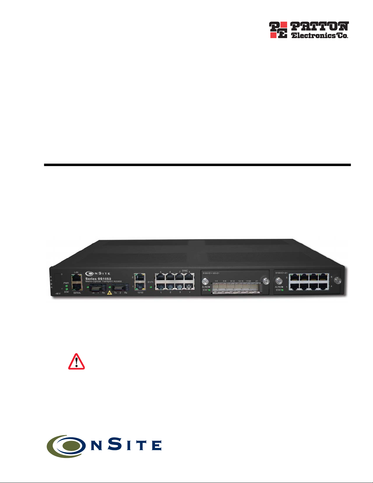
OnSite 1052 &1063 Series
Metro-Optical Transport
Access Nodes
Getting Started Guide
IMPORTANT
The compliance information in this document is incomplete and subject to change.
Sales Office: +1 (301) 975-1000
Technical Support: +1 (301) 975-1007
E-mail: support@patton.com
WWW: www.patton.com
Part Number: 07MOS10xx-GS, Rev. A
Revised: November 20, 2009
Page 2

Patton Electronics Company, Inc.
7622 Rickenbacker Drive
Gaithersburg, MD 20879 USA
Tel: +1 (301) 975-1000
Fax: +1 (301) 869-9293
Support: +1 (301) 975-1007
Web: www.patton.com
E-mail: support@patton.com
Copyright © 2009, Patton Electronics Company. All rights reserved.
The information in this document is subject to change without notice. Patton
Electronics assumes no liability for errors that may appear in this document.
The software described in this document is furnished under a license and may be used
or copied only in accordance with the terms of such license.
Page 3

Summary Table of Contents
1 Product Overview.......................................................................................................................................... 14
2 Application Overview.................................................................................................................................... 18
3 Installation Overview .................................................................................................................................... 23
4 System Management Access........................................................................................................................... 39
5 Contacting Patton for assistance ................................................................................................................... 53
A Compliance information .............................................................................................................................. 56
B Specifications ................................................................................................................................................ 59
C Terms and Acronyms .................................................................................................................................... 64
3
Page 4

Table of Contents
Summary Table of Contents ........................................................................................................................... 3
Table of Contents ........................................................................................................................................... 4
List of Figures ................................................................................................................................................. 7
List of Tables .................................................................................................................................................. 8
About this guide ............................................................................................................................................. 9
Audience................................................................................................................................................................. 9
Structure............................................................................................................................................................... 10
Precautions ........................................................................................................................................................... 10
Typographical conventions used in this document................................................................................................ 11
General conventions .......................................................................................................................................11
Mouse conventions .........................................................................................................................................11
Safety when using electricity ................................................................................................................................. 12
Power Cable ....................................................................................................................................................12
Electrostatic Discharge Damage............................................................................................................................ 13
Optical Safety ....................................................................................................................................................... 13
Fiber-Optic Ports ............................................................................................................................................13
Fiber-Optic Safety Precautions ........................................................................................................................13
1 Product Overview.......................................................................................................................................... 14
Introduction..........................................................................................................................................................15
OnSite Platforms ............................................................................................................................................15
2 Application Overview.................................................................................................................................... 18
OS1052 Application..............................................................................................................................................19
OS1063 Application..............................................................................................................................................21
3 Installation Overview .................................................................................................................................... 23
Introduction..........................................................................................................................................................24
Unpacking and Inspection.....................................................................................................................................24
Site Preparation .....................................................................................................................................................24
Site Environment ..................................................................................................................................................25
Planning Your Site.................................................................................................................................................25
Site Requirements ...........................................................................................................................................25
Operating Environment Requirements ......................................................................................................26
Power Supply Requirements ......................................................................................................................27
Distribution Rack Requirements ...............................................................................................................27
Mechanical Recommendations for the Rack ....................................................................................................28
Protective Grounding for the Rack and Chassis ..............................................................................................28
Space Requirements for the Rack ....................................................................................................................28
Securing the Rack ...........................................................................................................................................28
Tools and Equipment for Installation and Maintenance........................................................................................29
4
Page 5

5
OnSite Series Getting Started Guide
OnSite System Installation ....................................................................................................................................29
Mounting the Chassis to an EIA/TIA 19-Inch Rack .......................................................................................29
Mounting the Chassis to an ETSI Rack ..........................................................................................................30
Mounting the Chassis on the Wall ..................................................................................................................32
Installing the Chassis Ground Connection ......................................................................................................33
Connecting Power to the OS-10 System .........................................................................................................33
Connecting AC Power to the OS-10 System .............................................................................................34
Powering On the OS-10 System with AC Power ......................................................................................35
Connecting DC Power to the OS-10 System ............................................................................................35
Wiring Procedure for DC Input Power .....................................................................................................35
Checking the OS-10 System Installation .........................................................................................................38
4 System Management Access........................................................................................................................... 39
Introduction..........................................................................................................................................................40
General Overview..................................................................................................................................................40
Ethernet LAN Management Port...........................................................................................................................41
Serial Management Port ........................................................................................................................................42
Gaining Access to the System ................................................................................................................................43
Access through the Serial Port .........................................................................................................................43
Access through the Ethernet LAN Management Port ......................................................................................44
Web-Based Management Interface ........................................................................................................................45
Launching the GUI Application .....................................................................................................................45
Autonomous Alarm Messages ................................................................................................................................47
Engineering Orderwire (EOW) .............................................................................................................................49
5 Contacting Patton for assistance ................................................................................................................... 53
Introduction..........................................................................................................................................................54
Contact information..............................................................................................................................................54
Warranty Service and Returned Merchandise Authorizations (RMAs)...................................................................54
Warranty coverage ..........................................................................................................................................54
Out-of-warranty service .............................................................................................................................54
Returns for credit ......................................................................................................................................54
Return for credit policy .............................................................................................................................55
RMA numbers ................................................................................................................................................55
Shipping instructions ................................................................................................................................55
A Compliance information .............................................................................................................................. 56
Compliance ...........................................................................................................................................................57
EMC ...............................................................................................................................................................57
Safety ..............................................................................................................................................................57
Radio and TV Interference ....................................................................................................................................57
FCC Part 68 (ACTA) Statement ...........................................................................................................................57
Declaration of Conformity ....................................................................................................................................58
Authorized European Representative .....................................................................................................................58
B Specifications ................................................................................................................................................ 59
Page 6

6
OnSite Series Getting Started Guide
Model OS1052......................................................................................................................................................60
Trunk Interfaces .............................................................................................................................................60
Client Interfaces ..............................................................................................................................................60
Expansion Modules .........................................................................................................................................60
Configuration & Port Capacity for 2 Expansion Slots .....................................................................................60
Protection .......................................................................................................................................................60
Bandwidth Connectivity and Provisioning ......................................................................................................60
Timing & Synchronization .............................................................................................................................60
System Access .................................................................................................................................................60
Operations ......................................................................................................................................................61
Management ...................................................................................................................................................61
Packet Intelligence ..........................................................................................................................................61
Dimensions .....................................................................................................................................................61
Weight ............................................................................................................................................................61
Cooling ...........................................................................................................................................................61
Mounting .......................................................................................................................................................61
Power ..............................................................................................................................................................61
Environment ...................................................................................................................................................61
Model OS1063......................................................................................................................................................62
Trunk Interfaces .............................................................................................................................................62
Client Interfaces ..............................................................................................................................................62
Expansion Modules .........................................................................................................................................62
Configuration & Port Capacity for 2 Expansion Slots .....................................................................................62
Protection .......................................................................................................................................................62
Bandwidth Connectivity and Provisioning ......................................................................................................62
Timing & Synchronization .............................................................................................................................62
System Access .................................................................................................................................................62
Operations ......................................................................................................................................................63
Management ...................................................................................................................................................63
Packet Intelligence ..........................................................................................................................................63
Dimensions .....................................................................................................................................................63
Weight ............................................................................................................................................................63
Cooling ...........................................................................................................................................................63
Mounting .......................................................................................................................................................63
Power ..............................................................................................................................................................63
Environment ...................................................................................................................................................63
C Terms and Acronyms .................................................................................................................................... 64
Abbreviations.........................................................................................................................................................65
Page 7

List of Figures
1 OnSite Model 1052 . . . . . . . . . . . . . . . . . . . . . . . . . . . . . . . . . . . . . . . . . . . . . . . . . . . . . . . . . . . . . . . . . . . . . 15
2 OnSite Model 1063 . . . . . . . . . . . . . . . . . . . . . . . . . . . . . . . . . . . . . . . . . . . . . . . . . . . . . . . . . . . . . . . . . . . . . 16
3 OS1052 Base System . . . . . . . . . . . . . . . . . . . . . . . . . . . . . . . . . . . . . . . . . . . . . . . . . . . . . . . . . . . . . . . . . . . . 17
4 OS1063 Base System . . . . . . . . . . . . . . . . . . . . . . . . . . . . . . . . . . . . . . . . . . . . . . . . . . . . . . . . . . . . . . . . . . . . 17
5 Typical OS1052 application . . . . . . . . . . . . . . . . . . . . . . . . . . . . . . . . . . . . . . . . . . . . . . . . . . . . . . . . . . . . . . . 19
6 OS1052 Map + Modules . . . . . . . . . . . . . . . . . . . . . . . . . . . . . . . . . . . . . . . . . . . . . . . . . . . . . . . . . . . . . . . . . 20
7 Typical OS1063 application . . . . . . . . . . . . . . . . . . . . . . . . . . . . . . . . . . . . . . . . . . . . . . . . . . . . . . . . . . . . . . . 21
8 OS1063 Map + Modules . . . . . . . . . . . . . . . . . . . . . . . . . . . . . . . . . . . . . . . . . . . . . . . . . . . . . . . . . . . . . . . . . 22
9 Grounding Terminal Location for the OS-10 System Chassis . . . . . . . . . . . . . . . . . . . . . . . . . . . . . . . . . . . . . . 28
10 Mounting the OS-10 System Chassis in an EIA/TIA 19-Inch Rack . . . . . . . . . . . . . . . . . . . . . . . . . . . . . . . . . 30
11 Mounting the OS-10 System in an ETSI 300-mm Rack . . . . . . . . . . . . . . . . . . . . . . . . . . . . . . . . . . . . . . . . . . 31
12 Mounting the OS-10 System Chassis on a Wall . . . . . . . . . . . . . . . . . . . . . . . . . . . . . . . . . . . . . . . . . . . . . . . . 32
13 Wiring the OS-10 System for DC Power . . . . . . . . . . . . . . . . . . . . . . . . . . . . . . . . . . . . . . . . . . . . . . . . . . . . . 36
14 Serial and LAN Management Ports on the Base OS1052 and OS1063 Systems . . . . . . . . . . . . . . . . . . . . . . . . 40
15 Detail of the Management Ports . . . . . . . . . . . . . . . . . . . . . . . . . . . . . . . . . . . . . . . . . . . . . . . . . . . . . . . . . . . . 41
16 Location of Signal Pins on the RJ-45 Plug . . . . . . . . . . . . . . . . . . . . . . . . . . . . . . . . . . . . . . . . . . . . . . . . . . . . 41
17 Web-Based Management GUI Frames . . . . . . . . . . . . . . . . . . . . . . . . . . . . . . . . . . . . . . . . . . . . . . . . . . . . . . . 46
18 Configuring an SNMP Trap Receiver . . . . . . . . . . . . . . . . . . . . . . . . . . . . . . . . . . . . . . . . . . . . . . . . . . . . . . . . 47
19 Configuring an Authorized OnSight NMS Server . . . . . . . . . . . . . . . . . . . . . . . . . . . . . . . . . . . . . . . . . . . . . . 48
20 Location of EOW port (AUX 1) on OS-10 Series Chassis . . . . . . . . . . . . . . . . . . . . . . . . . . . . . . . . . . . . . . . . 49
21 Location of signal pins on the EOW port (AUX 1) RJ-11 connector . . . . . . . . . . . . . . . . . . . . . . . . . . . . . . . . 50
22 Configuring the Engineering Orderwire (EOW) Function . . . . . . . . . . . . . . . . . . . . . . . . . . . . . . . . . . . . . . . . 51
7
Page 8

List of Tables
1 General conventions . . . . . . . . . . . . . . . . . . . . . . . . . . . . . . . . . . . . . . . . . . . . . . . . . . . . . . . . . . . . . . . . . . . . . 11
2 Mouse conventions . . . . . . . . . . . . . . . . . . . . . . . . . . . . . . . . . . . . . . . . . . . . . . . . . . . . . . . . . . . . . . . . . . . . . . 11
3 Base System Configuration for OnSite Platforms . . . . . . . . . . . . . . . . . . . . . . . . . . . . . . . . . . . . . . . . . . . . . . . 16
4 Environmental Conditions for Operating the OS-10 System . . . . . . . . . . . . . . . . . . . . . . . . . . . . . . . . . . . . . . 26
5 Power Requirements for the OS-10 System . . . . . . . . . . . . . . . . . . . . . . . . . . . . . . . . . . . . . . . . . . . . . . . . . . . 27
6 Ground Wire Specifications . . . . . . . . . . . . . . . . . . . . . . . . . . . . . . . . . . . . . . . . . . . . . . . . . . . . . . . . . . . . . . . 33
7 OS-10 Power Options . . . . . . . . . . . . . . . . . . . . . . . . . . . . . . . . . . . . . . . . . . . . . . . . . . . . . . . . . . . . . . . . . . . 33
8 Power Consumption . . . . . . . . . . . . . . . . . . . . . . . . . . . . . . . . . . . . . . . . . . . . . . . . . . . . . . . . . . . . . . . . . . . . . 34
9 DC Wiring Requirements for the OS-10 System Chassis . . . . . . . . . . . . . . . . . . . . . . . . . . . . . . . . . . . . . . . . . 35
10 Ethernet LAN Management Port Cabling Specifications . . . . . . . . . . . . . . . . . . . . . . . . . . . . . . . . . . . . . . . . . 41
11 Pin Assignments for the Ethernet LAN Management Port . . . . . . . . . . . . . . . . . . . . . . . . . . . . . . . . . . . . . . . . 42
12 Pin Assignments for the RS-232 Serial Management Port . . . . . . . . . . . . . . . . . . . . . . . . . . . . . . . . . . . . . . . . . 42
13 RS-232 Serial Port Parameters . . . . . . . . . . . . . . . . . . . . . . . . . . . . . . . . . . . . . . . . . . . . . . . . . . . . . . . . . . . . . 42
14 VT100 Terminal Emulation Settings . . . . . . . . . . . . . . . . . . . . . . . . . . . . . . . . . . . . . . . . . . . . . . . . . . . . . . . . 42
15 Web-Based Management GUI Frame Descriptions . . . . . . . . . . . . . . . . . . . . . . . . . . . . . . . . . . . . . . . . . . . . . 46
8
Page 9

About this guide
This guide describes how to install a Patton OnSite Series Model 1052 and1063 Metro-Optical Transport
Access Node. For detailed configuration and management instructions, refer to the OnSite 1052 & 1063 Series
Administrator’s Reference Guide , which is located on the CD-ROM that came with your unit and at www.pat-
ton.com.
Installation, maintenance, and removal of a chassis or its components must be done by qualified service personnel only. Qualified service personnel have had appropriate technical training and experience that is necessary to be aware of the hazards to which they are exposed when performing a task and of measures to minimize
the danger to themselves and other people.
You should consider the following before unpacking your equipment:
• Install the equipment in a secured, enclosed, and restricted access area, ensuring that only qualified service
personnel have access to the equipment.
• Install the equipment only in a temperature and humidity-controlled indoor area that is free of airborne
materials that can conduct electricity.
• When you handle equipment that has expansion modules, put on the electrostatic discharge (ESD) wrist
strap to reduce the risk of electronic damage to the equipment.
Note
WARNING
Leave the ESD strap permanently attached to the chassis or rack so
that it is always available when you need to handle ESD-sensitive
components.
Read the following safety information thoroughly before installing your OS10 system. Failure to follow this safety information can lead to personal
injury or damage to the equipment.
Audience
This guide is intended for the following users:
• Operators
• Installers
• Maintenance technicians
9
Page 10

10
OnSite Series Getting Started Guide
Structure
This guide contains the following chapters and appendices:
• Chapter 1 describes the OnSite Series Metro-Optical Transport Access Nodes
• Chapter 2 describes typical applications for the OS-10 series
• Chapter 3 describes instructions for installing the OS-10
• Chapter 4 describes how to access the OS-10 for configuration and management
• Chapter 5 contains information on contacting Patton technical support for assistance
• Appendix A lists compliance information
• Appendix B contains specifications for the OS-10 series
• Appendix C contains a reference for terms and acronyms found in this guide
For best results, read the contents of this guide before you install the OS-10 platforms.
Precautions
Notes and cautions, which have the following meanings, are used throughout this guide to help you become
aware of potential problems. Warnings relate to personal injury issues, and Cautions refer to potential property
damage.
Note
WARNING
WARNING
CAUTION
Calls attention to important information.
The shock hazard symbol and WARNING heading indicate a potential electric
shock hazard. Strictly follow the warning instructions to avoid injury caused
by electric shock.
The alert symbol and WARNING heading indicate a potential safety hazard.
Strictly follow the warning instructions to avoid personal injury.
The shock hazard symbol and CAUTION heading indicate a
potential electric shock hazard. Strictly follow the instructions to
avoid property damage caused by electric shock.
The alert symbol and CAUTION heading indicate a potential hazard. Strictly follow the instructions to avoid property damage.
CAUTION
Page 11

OnSite Series Getting Started Guide
11
Typographical conventions used in this document
This section describes the typographical conventions and terms used in this guide.
General conventions
The procedures described in this manual use the following text conventions:
Table 1. General conventions
Convention
Garamond blue type
Futura bold type
Italicized Futura type
Futura type
Garamond bold type
< >
Are you ready?
% dir *.*
Indicates a cross-reference hyperlink that points to a figure, graphic,
table, or section heading. Clicking on the hyperlink jumps you to the reference. When you have finished reviewing the reference, click on the
Go to Previous View button in the Adobe® Acrobat® Reader tool-
bar to return to your starting point.
Indicates the names of menu bar options.
Indicates the names of options on pull-down menus.
Indicates the names of fields or windows.
Indicates the names of command buttons that execute an action.
Angle brackets indicate function and keyboard keys, such as <Shift> ,
<Ctrl> , <C> , and so on.
All system messages and prompts appear in the Courier font as the
system would display them.
Bold Courier font indicates where the operator must type a response or
command
Meaning
Mouse conventions
The following conventions are used when describing mouse actions:
Table 2. Mouse conventions
Convention Meaning
Left mouse button
Right mouse button This button refers the secondary or rightmost mouse button (unless you have
Point This word means to move the mouse in such a way that the tip of the pointing
Click Means to quickly press and release the left or right mouse button (as instructed in
Double-click Means to press and release the same mouse button two times quickly
Drag This word means to point the arrow and then hold down the left or right mouse but-
This button refers to the primary or leftmost mouse button (unless you have
changed the default configuration).
changed the default configuration).
arrow on the screen ends up resting at the desired location.
the procedure). Make sure you do not move the mouse pointer while clicking a
mouse button.
ton (as instructed in the procedure) as you move the mouse to a new location.
When you have moved the mouse pointer to the desired location, you can release
the mouse button.
Page 12

12
OnSite Series Getting Started Guide
Safety when using electricity
Read the installation instructions before connecting your OS-10 system to the
power source.
WARNING
Follow these guidelines when working on equipment powered by electricity:
• Locate the emergency power-off switch in the room in which you are working. Then, if an electrical acci-
dent occurs, you can quickly turn off the power.
• Never assume that power is disconnected from a circuit. Disconnect all power before installing or removing
a chassis or working near power supplies.
• Ground the unit. Do not connect the power supply unit to an AC outlet without a ground connection.
• Connect the unit to a grounded AC outlet to comply with the appropriate regional safety standards.
• Place the unit near the socket outlet to be easily accessible.
• Look carefully for possible hazards in your work area, such as moist floors, ungrounded power extension
cables, frayed power cords, and missing safety grounds.
• Do not work alone if hazardous conditions exist.
In addition, following these guidelines when working on any equipment that is disconnected from a power
source but still connected to telephone wiring or other network cabling:
• Never install telephone wiring during a lightning storm.
• Never touch uninsulated telephone wires or terminals unless the telephone line is disconnected at the net-
work interface.
• Use caution when installing or modifying telephone lines.
Power Cable
If your system comes with the AC power option, use an AC power cable appropriate for your country.
Check your local electrical codes and regulatory agencies for power cable requirements.
Page 13

13
OnSite Series Getting Started Guide
Electrostatic Discharge Damage
Electrostatic discharge (ESD) can damage equipment and impair electrical circuitry. It can occur if electronic
printed circuit cards are improperly handled and can cause complete or intermittent failures. Always follow
these ESD prevention procedures when removing and replacing expansion modules:
• Ensure that the system chassis is electrically connected to earth ground.
• Wear an ESD-preventive wrist strap, ensuring that it makes good skin contact. Connect the clip to an
unpainted surface of the chassis frame or to the rack to channel unwanted ESD voltages safely to ground.
To guard against ESD damage and shocks, the wrist strap and cord must operate effectively.
• If no wrist strap is available, ground yourself by touching an unpainted metal part of the chassis or rack.
To prevent equipment damage because of ESD, periodically
check the resistance value of the antistatic strap. It should be
CAUTION
between 1 and 10 M Ω (Mohm).
Optical Safety
Use fiber-optic ports only for telecommunications applications that require
optical fiber. Use the ports only with the appropriate connector. When not in
WARNING
Fiber-Optic Ports
To protect your eyes, never look at the transmit LED or laser through a magnifying device while it is powered
on. Never look directly at a fiber port on the chassis or at the ends of fiber cable when they are powered on.
Note
Fiber-Optic Safety Precautions
Follow these safety precautions when working with fiber-optic cables:
• Do not eat, drink or smoke in the work area. If fiber particles are ingested they could cause internal hemor-
rhaging.
• Wear safety glasses with side shields to avoid getting fiber-optic splinters in your eyes.
• Do not look into the end of a fiber cable until you are sure that there is no light source at the other end. Use
a fiber-optic power meter to ensure that the fiber is dark (that is, no power is being carried).
use, replace the dust covers. Using these interfaces in ways other than those
described in this guide can cause property damage or personal injury.
The OS-10 system uses a CLASS 1 laser device.
• Ensure that the work area is well ventilated.
• Do not touch your eyes while working with fiber-optic cables.
• Wear disposable aprons to minimize fiber particles on your clothing.
• Dispose of all cut fiber-optic pieces properly.
• Thoroughly clean the work area when the installation is complete.
Page 14

Chapter 1
Chapter contents
Introduction..........................................................................................................................................................15
OnSite Platforms ............................................................................................................................................15
Product Overview
14
Page 15
15
OnSite Series Getting Started Guide
1 • Product Overview
Introduction
The OnSite Series is family of ultra-compact, micro multi-service provisioning platforms (µMSPPs). The supports flexible and economic delivery of time division multiplexing (TDM) and Ethernet-based packet data services over synchronous digital hierarchy (SDH) transport networks.
The OS-10 system has two STM-1 ports for connection to the SDH network. The ports operate at 155.520
Mbit/s and can be configured to operate as dual unprotected ports or as a protected pair using Linear 1+1 MSP.
The STM-1 ports can also be configured in add-drop multiplexer (ADM) mode for operation in a ring network using SNCP path protection switching.
The OS-10 supports clear-channel mapping of E1/T1 and DS3/E3 signals into SDH payloads, and uses nextgeneration SDH features, such as generic framing procedure (GFP), virtual concatenation (VCAT), link capacitiy adjustment scheme (LCAS) and advanced packet intelligence functions for efficient transport of Ethernetbased data services.
The OS-10 has one Ethernet LAN management port and one RS-232 serial port for access to the system management functions. Remote access to OS-10 systems is possible through the use of an inband management
channel that uses either a dedicated E1 link over a VC-12 or the SDH data communications channel (DCC).
The OS-10 chassis can be mounted into a standard 19-inch EIA/TIA or a 300-mm ETSI rack. The chassis also
supports a wall-mounting option and can also be operated in a stand-alone desktop configuration.
The system uses natural convection cooling (that is, it contains no fans) and supports AC or DC power
options.
All cabling, other than AC power, is accessible from the front panel of the chassis. The system also provides
activity and status LEDs for all client-signal and SDH network interfaces. The system weighs approximately 5
kg (11 lbs) and has the following dimensions: 44.45 x 438.2 x 293 mm (height x weight x depth).
You can manage and access the OS-10 system through a simple Web-based graphical user interface (GUI)
called the OnSight Device Manager (DM) or a scalable network management system (NMS).
OnSite Platforms
The OS-10 Series has two modular platforms: the OS1052 and OS1063. Table 2 provides a summary of the
base system configuration for each platform.
Figure 1. OnSite Model 1052
Introduction
Page 16
16
OnSite Series Getting Started Guide
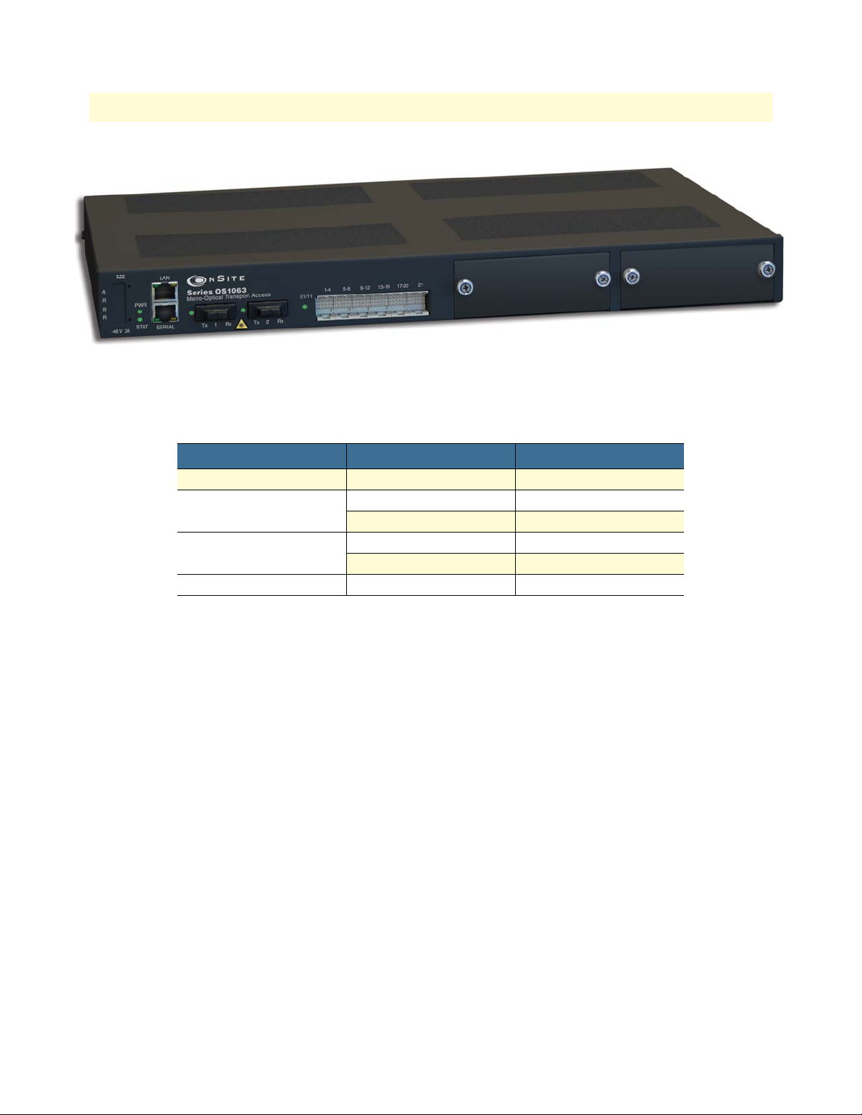
Table 3. Base System Configuration for OnSite Platforms
Type Model OS1052 Model OS1063
SDH Trunks 2 STM-1 2 STM-1
Client Signals 8 E1 or 8 T1 21 E1 or 21 T1
Management Serial RS-232 Serial RS-232
Expansion Slots 2 2
1 • Product Overview
Figure 2. OnSite Model 1063
2 Ethernet –
LAN LAN
The OS1052 and OS1063 systems have two expansion slots. The expansion slots support the insertion of the
following modules for flexible configuration changes and capacity upgrades:
• 21-port E1
• 3-port DS3/E3
• 2-port STM-1 optical and electrical
• 8-port Ethernet 10/100BASE-TX
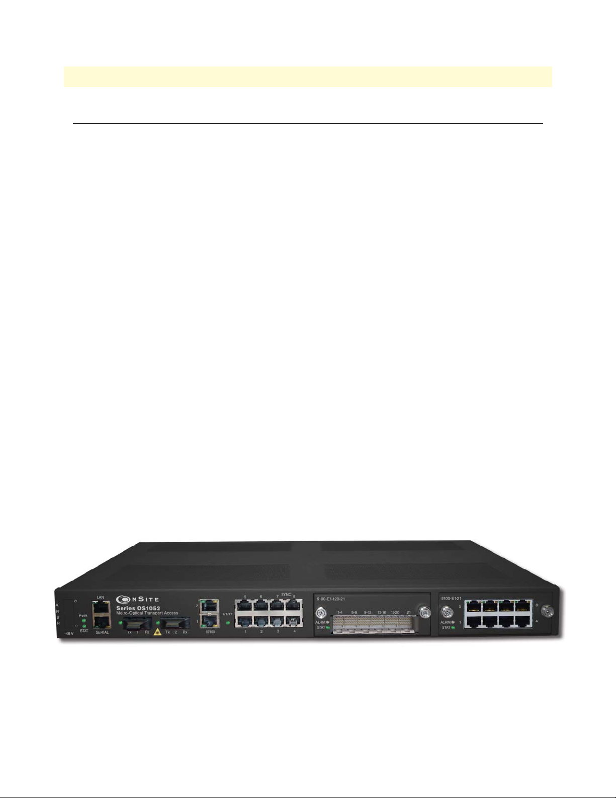
Figure 3 on page 17 shows the front and back panels of the OS1052 base system without the expansion mod-
ules installed. The OS1052 has eight built-in E1 and two built-in Ethernet 10/100BASE-TX interfaces. As a
factory-installed option, the OS1052 is also available with eight T1 ports. The OS1052 uses a future bus connector for access to the 8 E1 or T1 ports on the base system.
Introduction
Page 17

OnSite Series Getting Started Guide 1 • Product Overview
Figure 3. OS1052 Base System
Figure 2 shows the front panel of the OS1063 system. The OS1063 uses a future bus connector for access to
the 21 E1 or T1 ports on the base system. When the system is equipped with two 21-port high-density E1
(HD-E1) expansion modules, the OS1063 provides access for up to 63 E1 ports. (See chapter 12 for a description of the future bus connector and the features of the high-density E1 expansion module.) As a factoryinstalled option, the OS1063 is available with two STM-1 electrical interface (STM-1e) ports on the base system.
Figure 4. OS1063 Base System
Introduction 17
Page 18

Chapter 2 Application Overview
Chapter contents
OS1052 Application..............................................................................................................................................19
OS1063 Application..............................................................................................................................................21
18
Page 19
OnSite Series Getting Started Guide 2 • Application Overview
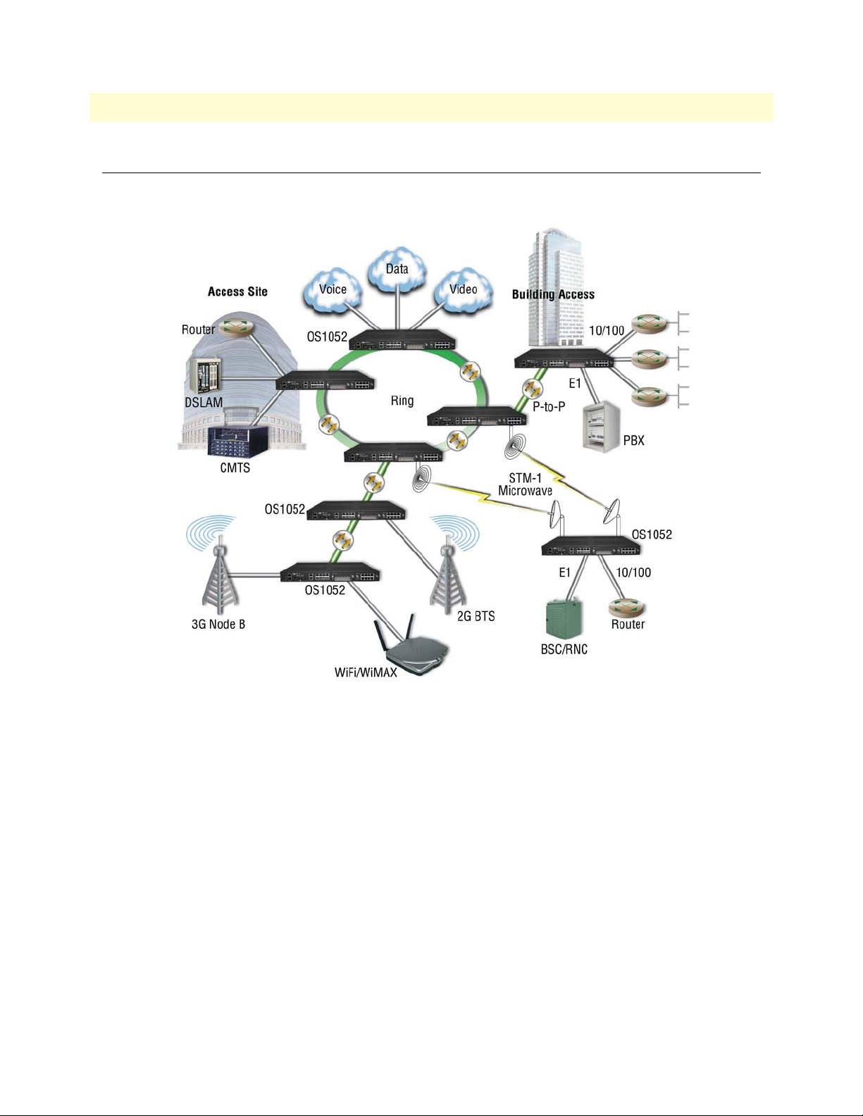
OS1052 Application
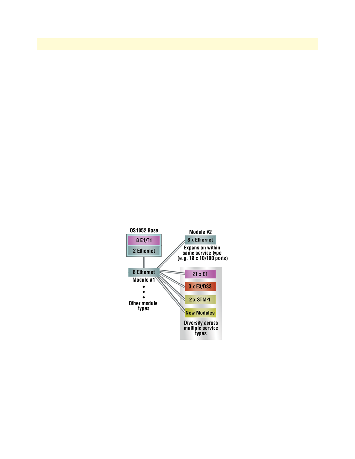
The advanced modular design of the Patton OnSite OS1052 provides unequaled flexibility in its class in terms
of service offerings, capacity and functional upgrades.
Figure 5. Typical OS1052 application
OS1052 Application 19
Page 20
OnSite Series Getting Started Guide 2 • Application Overview
The base OS1052 system is configured with:
• 2 STM-1
• 8 E1/T1
• 2 Ethernet
• 10/100Base-TX
Two expansion module slots allow increasing system capacity beyond the initial base configuration. Additional
ports and features only require simple insertion of one of the many available types of TDM and packet data
modules.
In only one RU, the OS1052 supports expansion up to:
• 50 E1 ports
• 18 Ethernet 10/100 ports
The OS1052 incorporates next-generation SDH features such as virtual concatenation (VCAT), link capacity
adjustment scheme (LCAS) and generic framing procedure (GFP) for efficient packet data transport. The platform also incorporates Layer 2 features such as VLAN tagging, rate limiting and statistical multiplexing with
multi-level QoS control. The OS1052 is easily configured and managed through a simple Web-based GUI
interface or the scalable Patton OnSight NMS.
Figure 6. OS1052 Map + Modules
OS1052 Application 20
Page 21
OnSite Series Getting Started Guide 2 • Application Overview
OS1063 Application
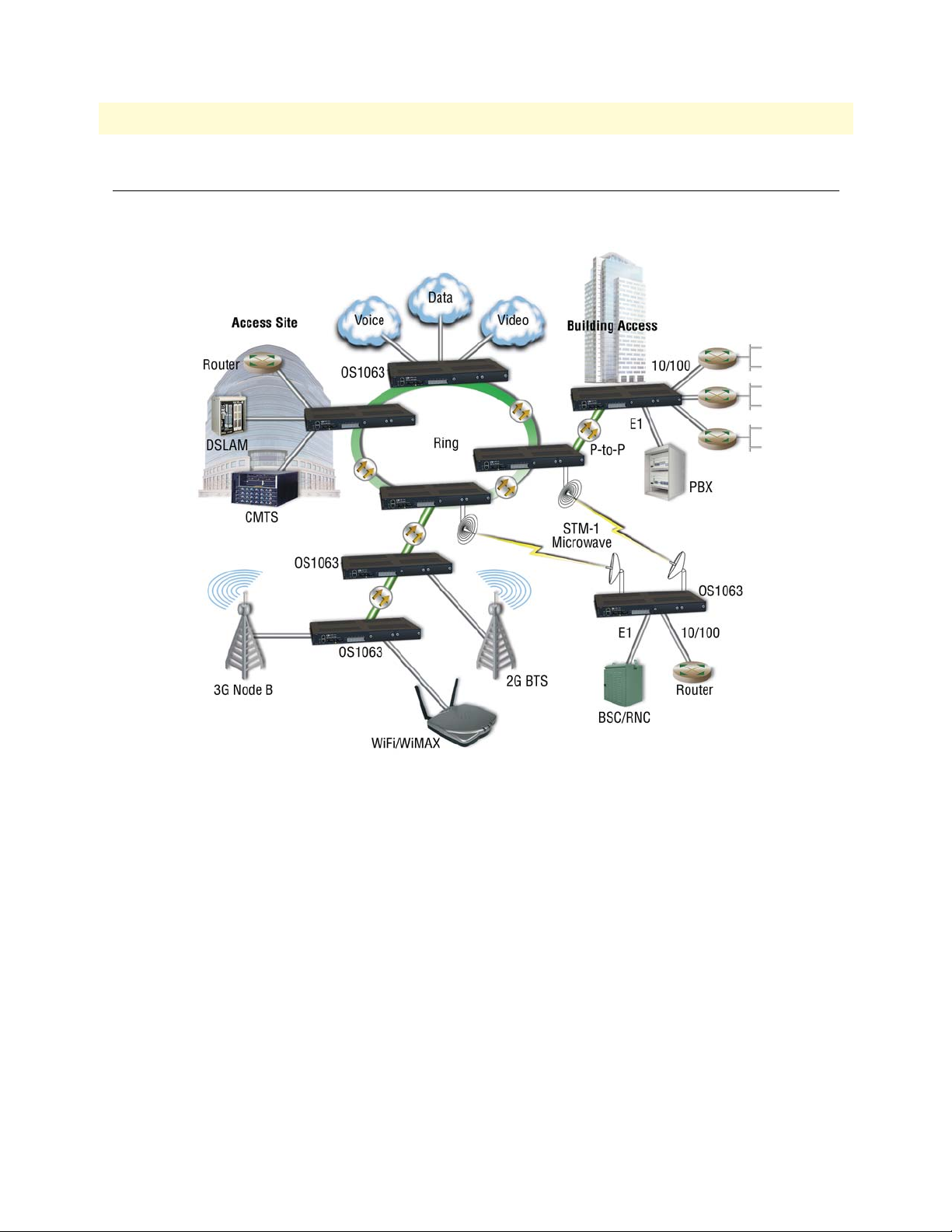
The advanced modular design of the Patton OnSite OS1063 provides unequaled flexibility in its class in terms
of service offerings, capacity and functional upgrades.
Figure 7. Typical OS1063 application
OS1063 Application 21
Page 22

OnSite Series Getting Started Guide 2 • Application Overview
The base OS1063 system is configured with:
• 2 STM-1
• 21 E1/T1
Two expansion module slots allow increasing system capacity beyond the initial base configuration. Additional
ports and features only require simple insertion of one of the many available types of TDM and packet data
modules.
In only one RU, the OS1063 supports expansion up to:
• 63 E1 ports
• 16 Ethernet 10/100 ports
The OS1063 incorporates next-generation SDH features such as virtual concatenation (VCAT), link capacity
adjustment scheme (LCAS) and generic framing procedure (GFP) for efficient packet data transport. The platform also incorporates Layer 2 features such as VLAN tagging, rate limiting and statistical multiplexing with
multi-level QoS control. The OS1063 is easily configured and managed through a simple Web-based GUI
interface or the scalable Patton OnSight NMS.
Figure 8. OS1063 Map + Modules
OS1063 Application 22
Page 23

Chapter 3 Installation Overview
Chapter contents
Introduction..........................................................................................................................................................24
Unpacking and Inspection.....................................................................................................................................24
Site Preparation .....................................................................................................................................................24
Site Environment ..................................................................................................................................................25
Planning Your Site.................................................................................................................................................25
Site Requirements ...........................................................................................................................................25
Operating Environment Requirements ......................................................................................................26
Power Supply Requirements ......................................................................................................................27
Distribution Rack Requirements ...............................................................................................................27
Mechanical Recommendations for the Rack ....................................................................................................28
Protective Grounding for the Rack and Chassis ..............................................................................................28
Space Requirements for the Rack ....................................................................................................................28
Securing the Rack ...........................................................................................................................................28
Tools and Equipment for Installation and Maintenance........................................................................................29
OnSite System Installation ....................................................................................................................................29
Mounting the Chassis to an EIA/TIA 19-Inch Rack .......................................................................................29
Mounting the Chassis to an ETSI Rack ..........................................................................................................30
Mounting the Chassis on the Wall ..................................................................................................................32
Installing the Chassis Ground Connection ......................................................................................................33
Connecting Power to the OS-10 System .........................................................................................................33
Connecting AC Power to the OS-10 System .............................................................................................34
Powering On the OS-10 System with AC Power ......................................................................................35
Connecting DC Power to the OS-10 System ............................................................................................35
Wiring Procedure for DC Input Power .....................................................................................................35
Checking the OS-10 System Installation .........................................................................................................38
23
Page 24

OnSite Series Getting Started Guide 3 • Installation Overview
Introduction
This chapter provides the procedures for installing the OnSite OS-10 system.
Unpacking and Inspection
Do not unpack the OS-10 system until you are ready to install it. If the final installation site will not be ready
for some time, keep the chassis in its shipping container to prevent accidental damage. When you are ready to
install the unit, proceed with unpacking it.
Note Do not discard the shipping cartons when you unpack the OS-10 sys-
tem. Flatten and store them. You will need the containers if you need
to move or ship the system. Repacking instructions will be provided
in your return material authorization (RMA) paperwork.
To check the contents of the shipping cartons, follow these steps:
1. Check the contents of the shipping container and accessories box or bag against the content list and the
packing slip which were included with your unit.
2. Verify that you received all listed equipment, including the following:
– OS-10 Series documentation (if ordered)
– Optional equipment that you ordered, such as network interface cables, or special connectors
3. Inspect all items for shipping damage.
Note If anything appears to be damaged or you encounter problems install-
ing or configuring your OS-10 Series chassis, contact customer service.
4. Check the expansion modules that may be located in each slot. Ensure that the configuration matches the
packing list and that all specified interfaces are included.
Site Preparation
This section describes the requirements your site must meet for safe installation and operation of your OnSite
OS-10 Series equipment. Ensure that the site is properly prepared before beginning installation.
The requirements described in this chapter are intended for the personnel responsible for installing and managing the network hardware. A working knowledge of telecommunications and local area network (LAN)
operations and a familiarity with communications protocols that are used on interconnected networks are
assumed. Installation, maintenance, and removal of a chassis, or its components must be done by qualified service personnel only. Qualified personnel have had appropriate technical training and experience that is necessary to be aware of the hazards to which they are exposed when performing a task and of measures to minimize
the danger to themselves and other people. By carefully planning your site, you can maximize the performance
of your existing network and ensure that it is ready to migrate to future service and capacity upgrades.
Introduction 24
Page 25

OnSite Series Getting Started Guide 3 • Installation Overview
Site Environment
The OS-10 system can be mounted in a rack or on a wall. The location of the chassis and layout of your equipment rack or wiring room are extremely important for proper system operation. Equipment that is too close
together, ventilation that is inadequate, and panels that are inaccessible can make system maintenance difficult
or cause system malfunctions and possible shutdowns.
The following precautions help you plan an acceptable operating environment for your OS-10 system and
avoid environmentally caused equipment failures:
• Ensure that the room in which you operate your system has adequate air circulation. Electrical equipment
generates heat. Ambient air temperature might not be able to cool equipment to acceptable operating temperatures without adequate circulation.
• Always follow the proper ESD-prevention procedures described in §3.2 (Electrostatic Discharge Damage)
to avoid damage to equipment. Damage from static discharge can cause immediate or intermittent equipment failure.
• Ensure that the chassis cover and all expansion slot covers are secure. The chassis is designed to allow cool-
ing air to flow effectively inside it. An open chassis allows air leaks, which might interrupt the flow of cooling air from internal components.
When planning your site layout and equipment location, remember the following precautions to help avoid
equipment failures and reduce the possibility of environmentally caused equipment problems.
Maximum recommended operating temperature – The maximum recommended operating temperature for
the OS-10 is 50°C (122°F). Determine a suitable operating environment based on this recommendation.
Elevated operating ambient temperature – If the unit is installed in a closed or multiunit rack assembly, the
operating temperature of the rack environment may be greater than the ambient temperature of the room.
Keep this in mind when you install the unit.
Reduced airflow – Install the OS-10 system chassis in the rack so that the amount of airflow required for safe
operation of the equipment is not compromised.
Mechanical load – Mount the OS-10 system chassis in the rack to avoid a potentially hazardous condition due
to uneven mechanical loading.
Circuit overload – When you connect the OS-10 system chassis to the supply circuit, consider the effect that
overloading of the circuits might have on over-current protection and supply wiring.
Reliable Ground – Maintain reliable grounding for the OS-10 system and all rack-mounted equipment, giving
particular attention to supply circuits.
Planning Your Site
Site Requirements
To install your OS-10 equipment successfully, you should plan your site carefully. The site planning process
has three major areas for consideration to ensure that your physical installation meets the requirements for a
safe and successful installation:
• Environmental, safety, and thermal requirements for the OS-10 system
• Power and local building and electrical code requirements
Site Environment 25
Page 26

OnSite Series Getting Started Guide 3 • Installation Overview
• Distribution rack requirements
The following sections provide further details for each area.
Operating Environment Requirements
You need to verify that your site meets all environmental and safety requirements. During the early planning
stages of installing or modifying your network, it is important that you develop a thorough understanding of
the regulations that pertain to your location and industry.
Temperature – The OS-10 system generates a specified amount of heat as indicated on the data sheet. It is
essential that you provide a temperature-controlled environment for both proper performance and safety.
Install the equipment only in a temperature- and humidity-controlled indoor area that is free of airborne materials that can conduct electricity.
The following are some general thermal recommendations for your wiring closet or equipment room:
• Ensure that the ventilation in the area is adequate to maintain a temperature below 50°C (122°F).
• Install a reliable air conditioning and ventilation system.
• Keep the ventilation in the wiring closet running during nonbusiness hours; otherwise, the equipment can
overheat.
• Maintain the following ambient operating temperature: 0° to 50° C (32° to 122°F)
• Maintain the following storage temperature: –40° to 70°C (–40° to 158°F)
Airflow requirements – To ensure proper airflow through the OS-10 equipment, follow these recommendations when you are installing your chassis:
• Leave 7.62 cm (3 inches) of minimum clearance on both the left and right sides of the chassis.
• Leave a half-rack unit (RU) of minimum clearance above and below the chassis for properairflow.
Note The OS-10 is a convection-cooled system, and adherence to these
clearance requirements is required for proper operation of the system.
Humidity – Keep the operating humidity between 5 and 95 percent relative humidity (noncondensing).
Table 4 summarizes the acceptable operational conditions for the OS-10 system.
Table 4. Environmental Conditions for Operating the OS-10 System
Environment Minimum Maximum
Temperature Ambient operating 5°C +40°C
Short-term (96 hours) 0°C +50°C
Humidity Short-term (96 hours) 5% 80%
Short-term (96 hours) 5% 95%
Altitude Ambient operating –60 m 1800 m
Planning Your Site 26
Page 27

OnSite Series Getting Started Guide 3 • Installation Overview
Power Supply Requirements
To operate your OS-10 equipment safely, follow these requirements:
• Ensure that your power supply meets the site power requirements of the equipment to be installed.
• Check the power at your site to ensure that you are receiving “clean” power (free of spikes and noise). Install
a power conditioner, if necessary.
• Ensure that DC connections are made by an on-site electrician.
• When connecting power to installed equipment, avoid connecting through an extension cord or apower
strip.
Table 5 summarizes the power requirements for the OS-10 system chassis.
Table 5. Power Requirements for the OS-10 System
Power Source
AC 110 or 220 VAC 1.0 A at 50 to 60 Hz 100 to 245 VAC
DC –48 VDC 2.0 A –36 to –72 VDC
Note If you system is shipped with the AC power option, use an AC power
Nominal Input
Voltage
Nominal Input
Current
cable appropriate for your country. Check your local electrical codes
and regulatory agencies for power cable requirements.
Note The system uses a universal AC power supply with an autoselection
function for operation with either 110 V (60 Hz) or 220 V (50 Hz).
Distribution Rack Requirements
The OS-10 can be installed in either a 19-inch EIA/TIA or ETSI 300-mm rack.
Note The 19-inch EIA/TIA rack should comply with the specification in
EIA-310-D.
Note The ETSI 300-mm rack should comply with the specification in
ETSI EN 300 119-3 V2.1.0 (2004-05).
Tolerance Limits
Planning Your Site 27
Page 28

OnSite Series Getting Started Guide 3 • Installation Overview
Mechanical Recommendations for the Rack
The following information will help you plan your equipment rack configuration:
• Use a rack made of steel or aluminum.
• Install equipment in the lower half of the rack first to avoid making the rack top heavy.
• The rack should be able to support the full weight of the final installed chassis.
• Enclosed racks must have adequate ventilation. Ensure that the rack is not overly congested because each
unit generates heat. An enclosed rack should have louvered sides and a fan to provide cooling air.
• When mounting a chassis in an open rack, ensure that the rack frame does not block the cooling holes. If
the chassis is installed on slides, check the position of the chassis when it is seated all the way into the rack.
• In an enclosed rack with a ventilation fan in the top, excessive heat generated by equipment near the bot-
tom of the rack can be drawn upward and into the intake ports of the equipment above it in the rack. In
addition, ensure that you provide adequate ventilation for equipment at the bottom of the rack.
• Baffles can help isolate exhaust air from intake air, which also helps draw cooling air through the chassis.
The best placement of the baffles depends on the airflow patterns in the rack, which can be found by experimenting with different arrangements.
Protective Grounding for the Rack and Chassis
Use a rack grounding kit and a ground conductor that is carried back to earth or another suitable building
ground. The OS-10 chassis is designed with mounting brackets that provide solid metal-to-metal connection
to the rack. If you do not use equipment racks, you can attach a wiring terminal directly to the chassis at the
position indicated for appropriate grounding. Figure 9 shows the location of the grounding terminal location
for the OS-10 chassis.
Figure 9. Grounding Terminal Location for the OS-10 System Chassis
Note
Because building codes vary worldwide, OnSite Systems strongly recommends that you consult an electrical contractor to ensure that
proper equipment grounding is in place for your specific installation.
Space Requirements for the Rack
Provide enough space in front of and behind the OS-10 system chassis so that you can service it easily. Typically, allow a minimum of 122 cm (48 inches) in front of the rack and 61 cm (24 inches) behind the rack.
Securing the Rack
The rack should be attached to the equipment room floor with 9.5-mm (3/8-inch) lag screws or equivalent
hardware. The floor under the rack should be level within 5 mm (3/16 inch). Use a floor-leveling cement compound if necessary or bolt the racks to the floor.
Planning Your Site 28
Page 29

OnSite Series Getting Started Guide 3 • Installation Overview
Tools and Equipment for Installation and Maintenance
You need the following tools and equipment to install or upgrade the OS-10 system and its components:
• ESD-preventive cord and wrist strap (when working with modular components or expansion cards)
• Number 1 or number 2 Phillips screwdriver
• Mounting brackets (provided); two are required for rack mounting or for wall mounting
• 8 screws (provided) to secure the L mounting brackets to the OS-10 system chassis (four screws for each
bracket)
• A minimum of four 12-24 x 3/4-inch screws (not provided) to secure the OS-10 system chassis to the rack
• Suitable screws and wall anchors to install an OS-10 system on a wall
• Cable ties, if required, for organizing cables
In addition, depending on the type of modules you plan to use, you might need the following equipment to
connect the OS-10 system to an external network:
• Cables for connection to the fiber-optic and client signal ports (depending on configuration)
• Ethernet hub or PC with a network interface card for connection to Ethernet LAN ports
• Console terminal (an ASCII terminal or a PC running terminal emulation software) configured for 9,600
baud, 8 data bits, no parity, and 1 stop bit
OnSite System Installation
Note Read the information in this section thoroughly and completely
before you attempt to install or remove an OS-10 Series system chassis.
Only trained and qualified personnel should be allowed to install, replace, or
service this equipment.
WARNING
Mounting the Chassis to an EIA/TIA 19-Inch Rack
To install the OS-10 system chassis in an EIA/TIA 19-inch rack, see Figure 10 and follow these steps:
1. Install the two L mounting brackets in the orientation shown in Figure 10. Insert and fully tighten the
screws to secure the brackets to the chassis (four screws for each bracket).
Note For this rack configuration, the L mounting bracket holes are flush
with the front panel of the OS-10 system, as shown in Figure 4.
2. Position the chassis in the rack and align the mounting holes in the L bracket with the mounting holes in
the equipment rack.
Note The mounting-hole pitch for the 19-inch rack has the following
repetitive pattern: 5/8”- 5/8”-1/2”.
Tools and Equipment for Installation and Maintenance 29
Page 30

OnSite Series Getting Started Guide 3 • Installation Overview
Note Take care to load the rack so that it is not top heavy.
Note Do not cover vents that would restrict airflow. Leave a minimum of a
half-rack space above and below the OS-10 system for adequate ventilation.
3. Secure the chassis using four 12-24 x 3/4-inch screws (two screws for each side) through the elongated
holes in the L bracket nearest to the chassis and to the threaded holes in the mounting post. Use a suitable
screwdriver for this task.
4. Tighten any loose captive installation screws on the expansion slot front panel covers.
Figure 10. Mounting the OS-10 System Chassis in an EIA/TIA 19-Inch Rack
Mounting the Chassis to an ETSI Rack
To install the OS-10 system chassis in an ETSI 300-mm rack, see Figure 11 and follow these steps:
1. Install the two L mounting brackets in the orientation shown in Figure 11. Insert and fully tighten the
screws to secure the brackets to the chassis (four screws for each bracket). Use a suitable screwdriver for this
task.
Note For this rack configuration, the L mounting bracket holes are posi-
tioned 50 mm back from the front panel of the OS-10 system, as
shown in Figure 11.
2. Position the chassis in the rack and align the mounting holes in the L bracket with the mounting holes in
the equipment rack.
Note The mounting-hole pitch for the ETSI 300 mm rack is 25 mm.
Note Take care to load the rack so that it is not top heavy.
OnSite System Installation 30
Page 31

OnSite Series Getting Started Guide 3 • Installation Overview
Note Do not cover vents that would restrict airflow. Leave a minimum of a
half-rack space above and below the OS-10 system for adequate ventilation.
3. Secure the chassis using four 12-24 x 3/4-inch screws (two screws for each side) through the elongated
holes in the L bracket nearest to the chassis and to the threaded holes in the mounting post. Use a suitable
screwdriver for this task.
4. Tighten any loose captive installation screws on the expansion slot front panel covers.
Figure 11. Mounting the OS-10 System in an ETSI 300-mm Rack
OnSite System Installation 31
Page 32

OnSite Series Getting Started Guide 3 • Installation Overview
Mounting the Chassis on the Wall
Note When choosing a wall-mounting location, consider the cable limita-
tions and the wall structure. Use the four L brackets provided for rack
mounting to mount the chassis on a wall. The brackets provide the
most stable installation for the chassis.
1. Install the two L mounting brackets in the orientation shown in Figure 12. Insert and fully tighten the
screws to secure the brackets to the chassis (four screws for each bracket). Use a suitable screwdriver for this
task.
Note For this rack configuration, the L mounting bracket holes are flush
with the bottom panel of the OS-10 system chassis.
2. Position the chassis against the wall using wall mount option 1 or option 2, as shown in Figure 12.
3. Secure the chassis to the wall using four 12-24 x 3/4-inch screws (two screws for each side) through the
elongated holes in the L bracket nearest to the chassis. Use a suitable screwdriver for this task.
4. Tighten any loose captive installation screws on the expansion slot front panel covers.
Figure 12. Mounting the OS-10 System Chassis on a Wall
OnSite System Installation 32
Page 33

OnSite Series Getting Started Guide 3 • Installation Overview
Installing the Chassis Ground Connection
The OS-10 system chassis requires a reliable earth ground connection. You must connect the chassis to a reliable earth ground. The ground wire must be installed in accordance with local electrical safety standards.
Table 6. Ground Wire Specifications
Grounding Standard Wire
EN/IEC 60950 AWG 18 (1 mm2) or larger wire and an
appropriate user-supplied ring terminal
NEBS AWG 6 (13 mm2) wire and the ground
lug provided in the accessory kit
NEC (National Electric Code) AWG 14 (2 mm2) or larger wire and an
appropriate user-supplied ring terminal
To connect the OS-10 system chassis to a reliable earth ground, follow these steps:
1. Strip one end of the ground wire to the length required for the ground lug or terminal.
Note For the NEBS ground lug, the length is approximately 0.75 inches
(20 mm)
Note For a user-provided ring terminal—as required
2. Crimp the ground wire to the ground lug or ring terminal, using a crimp tool of the appropriate size.
3. Attach the ground lug or ring terminal to the chassis grounding terminal location shown in Figure 3.
4. Connect the other end of the ground wire to a suitable grounding point at your site.
After installation and proper grounding of the OS-10 chassis, you can connect the following:
• Power wiring
• Cables for the fiber-optic interface and Category 5 cables for E1 and Ethernet client signal interfaces
• Category 5 cables for the Ethernet LAN and SERIAL management ports
Connecting Power to the OS-10 System
The system supports AC and DC power options, as listed in Table 7. These options are factory installed.
Table 7. OS-10 Power Options
Power Options Nominal Input Tolerance Limit Feature
AC 110 VAC at 50 Hz and
220 VAC at 60 Hz
DC –48VDC –36 to –72 VAC Auto-switching AC to DC power converter
100 to 245 VAC Auto-switching AC to DC power converter
Note Both AC and DC options provide short-circuit and over-voltage pro-
tection.
Note The DC option provides reverse input polarity protection.
OnSite System Installation 33
Page 34
OnSite Series Getting Started Guide 3 • Installation Overview
Note The DC-to-DC converter has dual power inputs (A and B power).
The system continues to operate normally if either the A or B power
input fails.
The system uses natural convection for heat dissipation (that is, it does not use fans). The absence of fans
increases system reliability and eliminates periodic maintenance visits for fan filter replacement.Table 8 pro-
vides the maximum power consumption figures for the OS-10 system under normal operating conditions.
Table 8. Power Consumption
System Configuration Maximum Power (W)
Base system 40
Base system with a single expansion module 50
Base system with dual expansion modules 60
This section explains how to connect the AC or DC power to the OS-10 system chassis.
Read the installation instructions before connecting the system to the power
source.
WARNING
Do not work on the system or connect or disconnect cables during periods of
lightning activity.
WARNING
The installation must comply with all required electrical codes applicable at the installation site.
Connecting AC Power to the OS-10 System
If your OS-10 system uses AC power, connect it to a 15 A at 120 VAC (or 10 A at 240 VAC) circuit with overcurrent protection.
Note The input voltage tolerance limits for AC power are 100 to 245 VAC.
•AC-connected units must have a permanent ground connection in addition to
the power cable ground wire. NEBS-compliant grounding satisfies this
WARNING
requirement.
•This product relies on the installation of the building for short-circuit (overcurrent) protection. Ensure that the protective device is rated not greater
than: 15A at 120 VAC (or 10 A at 240 VAC).
•The AC power supply for the OS-10 system has Double Pole/Neutral Fusing.
OnSite System Installation 34
Page 35

OnSite Series Getting Started Guide 3 • Installation Overview
Powering On the OS-10 System with AC Power
To power on the OS-10 system using AC power, follow these steps:
1. Connect the AC power cable to the OS-10 system and then to the wall outlet.
2. Turn the power switch on the back panel of the OS-10 system to the ON position.
Note The green PWR (power) LED on the front panel is lit when the sys-
tem receives power from the AC source.
After turning off the AC power switch, wait for at least 3 seconds
before turning it back to the on position.
CAUTION
Connecting DC Power to the OS-10 System
If your OS-10 system has a DC-input power supply terminal block on the front panel, follow the directions in
this section for proper wiring.
This product relies on the installation of the building for short-circuit (overcurrent) protection. Ensure that the protective device is rated not greater than
WARNING
15 A at 60 VDC.
Table 9 summarizes the wiring requirements for the OS-10 system chassis with a DC-input power supply.
Note For installations compliant with the National Electric Code, an AWG
14 (2.0 mm2) wire is required for DC input and safety ground wire.
Table 9. DC Wiring Requirements for the OS-10 System Chassis
DC Nominal Input DC Input Wire Size
–48 VDC at 2.0 A
Note The input voltage tolerance limits for nominal –48 VDC power sup-
AWG 18 (1.0 mm2) AWG 14 (2.0 mm2)
Safety Ground
Wire Size
Over-Current Protection
15 A
plies is –36 to –72 VDC.
Wiring Procedure for DC Input Power
To connect DC power to the OS-10 system, see Figure 13 and follow these steps:
•Connect the DC input wires to the OS-10 system with the following wiring
sequence.
Figure 13 shows the terminal block for the DC power supply on the OS-10
WARNING
•
system. Wire the DC power supply as shown.
OnSite System Installation 35
Page 36

OnSite Series Getting Started Guide 3 • Installation Overview
Figure 13. Wiring the OS-10 System for DC Power
1. Choose an available circuit from a DC power source and identify both the positive and negative leads for
this circuit.
Note The DC power source may be a DC circuit breaker or an AC-to-DC
power rectifier.
•Do not touch the circuit with your hands or with any other instrument until
you make sure that there is no power present on the circuit.
WARNING
•Make sure that power is removed from the DC circuit that will supply power
to the OS-10 system before performing any of the following procedures.
2. Remove power from this circuit.
Note To ensure that power is removed from the DC circuit, locate the cir-
cuit breaker for the DC circuit, switch the circuit breaker to the OFF
position, and tape the circuit-breaker switch in the OFF position.
3. Strip the DC input wires that will connect the circuit to the DC power terminal block on the OS-10 system to the appropriate length.
4. Connect the positive lead of this circuit to ground. See wiring 1-A in Figure 13.
Note As an option, you may choose another common grounding point
other than the one shown in Figure 13. The choice depends on the
grounding practice for your particular location. Figure 13 shows the
grounding point colocated with the DC circuit for “A” power.
OnSite System Installation 36
Page 37

OnSite Series Getting Started Guide 3 • Installation Overview
The ground wire should always be connected first and disconnected last.
CAUTION
5. Connect the positive lead of the circuit to the return direction for “A” power on the OS-10 system terminal block. See wiring 2-A in Figure 7.
Note The terminal block indicates the return direction for “A” power by
the letter R. This lead is second from the top on the OS-10 system
terminal block.
Note Step 4 and Step 5 results in the grounding of the return direction for
“A” power on the OS-10 system terminal block.
6. Connect the negative lead of the circuit to the “A” power input lead on the OS-10 system terminal block.
See wiring 3-A on figure 13 on page 36.
Note The terminal block indicates the “A” power lead by the letter A. This
lead is first from the top on the OS-10 system terminal block.
Continue with the following steps if a second circuit is available for the provision of redundant “A” and
“B” DC power inputs on the system. Otherwise, go directly to Step 10 to complete this task.
7. Connect the positive lead of this circuit to ground. See wiring 1-B on figure 13 on page 36.
Note As an option, you may choose another common grounding point
other than the oneshown in Figure 13. The choice depends on the
grounding practice for your particular location. Figure 13 shows the
grounding point colocated with the DC circuit for “B” power.
The ground wire should always be connected first and disconnected last.
CAUTION
8. Connect the positive lead of the circuit to the return direction for “B” power on the OS-10 Series system
terminal block. See wiring 2-B on Figure 13.
Note The terminal block indicates the return direction for “B” power by
the letter R. This lead is fourth from the top on the OS-10 system
terminal block.
Note Step 7 and Step 8 result in the grounding of the return direction for
“B” power on the OS-10 system terminal block.
OnSite System Installation 37
Page 38

OnSite Series Getting Started Guide 3 • Installation Overview
9. Connect the negative lead of the circuit to the “B” power input lead on the OS-10 system terminal block.
See wiring 3-B on figure 13 on page 36.
Note The terminal block indicates the “B” power lead by the letter B. This
lead is third from the top on the OS-10 system terminal block.
Do not over torque the terminal block captive thumbscrew or terminal block contact screws.
CAUTION
10. Secure the wires using cable ties or similar appropriate cable tie-downs.
11. Turn on power to the DC circuit.
Note The green PWR (power) LED on the front panel is lit when the sys-
tem receives power from the DC source.
Checking the OS-10 System Installation
When you first apply power to the system, the STAT (status) LED shows a solid amber light. This light indicates that the system is booting. The STAT LED turns to a solid green light when the system completes the
boot process and is ready for operation.
OnSite System Installation 38
Page 39

Chapter 4 System Management Access
Chapter contents
Introduction..........................................................................................................................................................40
General Overview..................................................................................................................................................40
Ethernet LAN Management Port...........................................................................................................................41
Serial Management Port ........................................................................................................................................42
Gaining Access to the System ................................................................................................................................43
Access through the Serial Port .........................................................................................................................43
Access through the Ethernet LAN Management Port ......................................................................................44
Web-Based Management Interface ........................................................................................................................45
Launching the GUI Application .....................................................................................................................45
Autonomous Alarm Messages ................................................................................................................................47
Engineering Orderwire (EOW) .............................................................................................................................49
39
Page 40
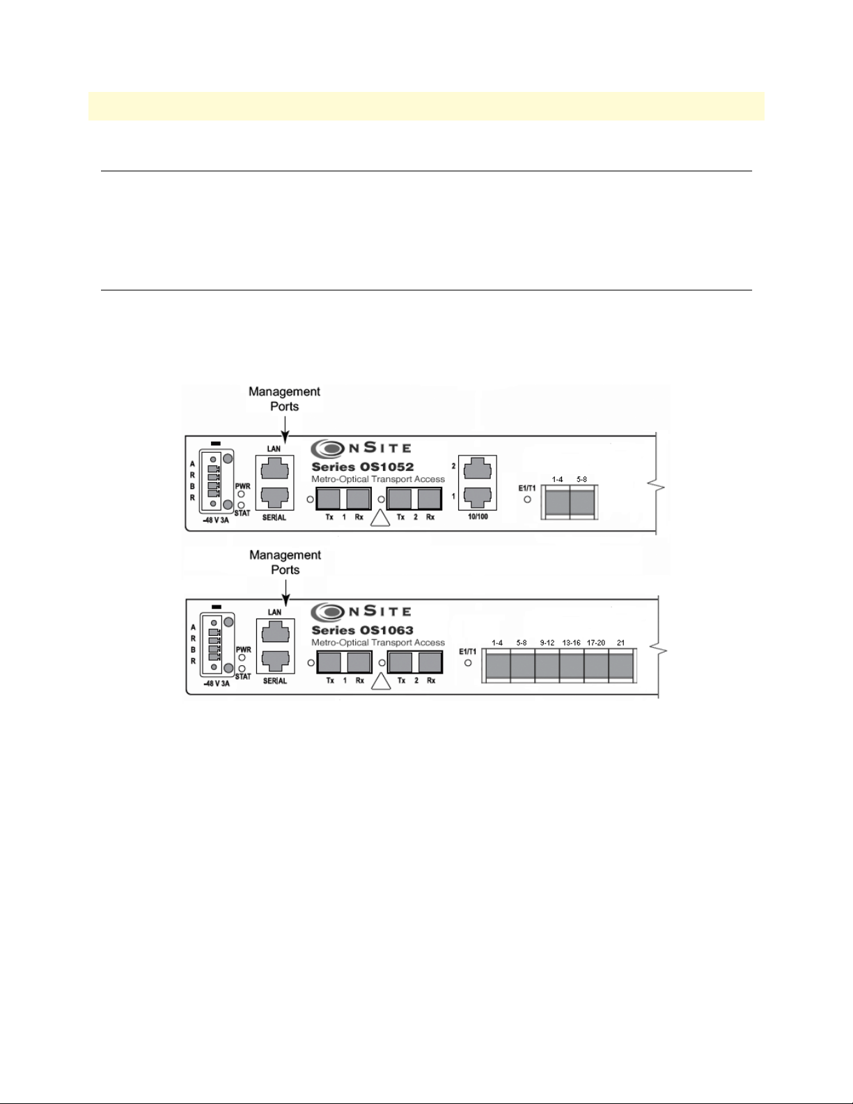
OnSite Series Getting Started Guide 4 • System Management Access
Introduction
This chapter provides the procedures for configuring and monitoring the local serial and LAN management
(LM) ports, and the inband management channel (IMC) for remote management communications. The chapter also provides the procedures for configuring and using the Orderwire communications port (if the AUX
port is factory-installed).
General Overview
The base OnSite OS-10 system provides two management ports from which you can access the system management functions. One of the management ports is an Ethernet LAN (10/100BASE-TX) port. The other is
an RS-232 SERIAL port.
Figure 14 shows the location of the two management ports on the base OS1052 and OS1063 systems.
Figure 14. Serial and LAN Management Ports on the Base OS1052 and OS1063 Systems
Introduction 40
Page 41

OnSite Series Getting Started Guide 4 • System Management Access
Figure 15 provides a close-up view of the two management ports. The figure includes the location of the RJ-45
connector pins for both ports.
Figure 15. Detail of the Management Ports
Figure 16 shows the location of the signal pins on the RJ-45 plug.
Figure 16. Location of Signal Pins on the RJ-45 Plug
Ethernet LAN Management Port
The Ethernet LAN management port complies with the following standards:
• IEEE 802.3u (PHY)
• IEEE 802.3 (MAC)
• IEEE 802.3x (flow control)
The port supports autonegotiation, which is always enabled.
Table 10 provides the cabling specifications for the Ethernet LAN management port.
Table 10. Ethernet LAN Management Port Cabling Specifications
Cable Specification
Connector RJ-45
Type Category 5
Reach 100 m
Ethernet LAN Management Port 41
Page 42

OnSite Series Getting Started Guide 4 • System Management Access
Table 11 provides the pin assignments for the RJ-45 connector.
Table 11. Pin Assignments for the Ethernet LAN Management Port
Signal Name Description RJ-45 Pin
RXN Receive tip 3
RXP Receive ring 6
TXN Transmit tip 1
TXP Transmit ring 2
Serial Management Port
The physical connector for the RS-232 SERIAL management port is an RJ-45 connector. Table 12 provides
the pin assignments for the RJ-45 connector.
Note A connector adapter is supplied with the system to allow the connec-
tion of the RS-232 signal to a PC with a DB-9 connector.
Table 12. Pin Assignments for the RS-232 Serial Management Port
Signal Name Description RJ-45 Pin
RS232_TXD output Transmit data 6
RS232_RXD input Receive data 3
GND Ground 4 and 5
Table 13 lists the serial port parameters:
Table 13. RS-232 Serial Port Parameters
Parameter Property
Baud rate 9,600 to 38,400 (asynchronous)
Data 8 bits
Parity None
Stop 1 bit
Table 14 lists the required VT100 terminal emulation settings for the PC that connects to the serial port.
Table 14. VT100 Terminal Emulation Settings
Parameter Setting
Port COM1
Baud rate 9,600
Data 8 bits
Parity None
Stop 1 bit
Flow control None
Serial Management Port 42
Page 43

OnSite Series Getting Started Guide 4 • System Management Access
Gaining Access to the System
There are two ways of gaining access to the system management functions. One way is through the SERIAL
port and the command line interface (CLI). The other way is through the Ethernet LAN port and the web
browser interface. The following sections describe the procedures for each of the access methods.
Access through the Serial Port
To gain management access to the system for the first time through the SERIAL port, follow these steps:
1. Connect a PC to the SERIAL management port.
Note Use the DB-9-to-RJ-45 adapter cable supplied with the system.
2. Launch the VT100 terminal emulation program on the PC.
Note Configure the terminal in accordance with the settings in Table 14.
3. Press the Enter key on the PC to obtain a login prompt from the system.
4. Log in to the system using the Super user ID and password.
Note Only the Super user is able to perform the following task.
Note The user ID for the Super user is super (all lowercase letters).
Note The factory-assigned default password for the Super user is super (all
lowercase letters).
After successful completion of the login, the system responds with the CLI (command-line interface)
prompt.
Note The CLI command prompt for the system is OnSite >
5. Type the following CLI command to configure the IP address for the Ethernet LAN management port,
and then press the Enter key:
config mgmt-enet ip-address aaa.bbb.ccc.ddd
Note aaa.bbb.ccc.ddd is the standard dotted-decimal notation.
6. Type the following CLI command to configure the net mask for the Ethernet LAN management port, and
then press the Enter key:
config mgmt-enet ip-netmask aaa.bbb.ccc.ddd
7. Type the following CLI command to configure the default gateway for the Ethernet LANmanagement
port, and then press the Enter key:
config mgmt-enet default-gateway aaa.bbb.ccc.ddd
Note By default, the IP address is set to 192.168.2.100, the net mask is set
to 255.255.255.0, and the default gateway is set to 192.168.2.1
Gaining Access to the System 43
Page 44

OnSite Series Getting Started Guide 4 • System Management Access
8. Type the following CLI command to save the IP settings (address, net mask, and default gateway)for the
Ethernet LAN management port to the system configuration file, and then press the Enter key:
save config
Note Saving the configuration is important to prevent the loss of the IP
configuration data if a system reset or reboot occurs.
Changing the IP address, net mask, and default gateway settings
for the Ethernet LAN management port could result in the loss-of-
CAUTION
management connectivity to the system, if the connection is currently through that port.
At this point, the system responds with Configuration Saved to indicate that the IP settings have been saved to
the system. The system is now ready for operation using the Web-based management interface.
Note You may also have access to the system through Telnet. This access
requires prior configuration of the IP address of the Ethernet LAN
management port through the RS-232 SERIAL port, as indicated in
the preceding steps.
Note The system terminates the management session for any user when the
session remains inactive for 30 seconds. This termination applies to
management sessions through the SERIAL port or through Telnet.
The login prompt appears when the system terminates a previously
active session through the SERIAL port.
Access through the Ethernet LAN Management Port
To gain management access to the system for the first time through the Ethernet LAN management (LM) port,
follow these steps:
1. Connect a PC to the Ethernet LAN management port using the RJ-45 connector.
Note You may connect the PC to the system from a remote location using
an IP LAN or WAN that connects to the Ethernet LAN management
port.
2. Configure the PC using the factory default settings for the Ethernet LAN management port.
Note By default, the IP address is set to 192.168.2.100, the net mask is set
to 255.255.255.0, and the default gateway is set to 192.168.2.1
3. Launch the Web browser of your choice, and type the default IP address of the system in the Address field
of the browser.
4. Log in to the system using the super, admin, or monitor user ID and password.
Note The factory-assigned default password for the Super user is super (all
lowercase letters).
Gaining Access to the System 44
Page 45

OnSite Series Getting Started Guide 4 • System Management Access
See “Web-Based Management Interface” on page 45 for a description of the Web-based management interface
features. Once you gain access to the system through the Ethernet LAN port, you may change the IP settings
for the port for secure access in the future.
5. Refer to the OnSite Series Administrator’s Reference Guide, located on the CD that came with your unit and
online at www.patton.com for instructions on how to change the IP settings for the Ethernet LAN port.
Save the system configuration to prevent the loss of the new IP
settings if a system reboot occurs.
CAUTION
Note Once the changes take place, you will loose connectivity to the sys-
Refer to the OnSite Series Administrator’s Reference Guide,
located on the CD that came with your unit and online at
www.patton.com for instructions.
tem, but you can regain access immediately by typing the new IP
address of the system in the Address field of the browser.
Web-Based Management Interface
The system provides a simple but powerful Web-based management interface to configure and monitor the
OnSite OS-10 system. This graphical user interface (GUI) is called the OnSight Device Manager (DM) and is
accessible through a Web browser using Hypertext Transfer Protocol (HTTP).
Note The system supports the following Web browsers: Microsoft Internet
Explorer 6+, Netscape 7+, Mozilla 1.7+, and Mozilla Firefox 1.0+ on
Windows, Solaris, and Linux platforms.
The OnSight DM allows you to have full access to the system management functions. These functions include
the ability to set up or change all configurable items on the system and the ability to create and delete connections between the client ports and SDH network interface. The interface also allows you to monitor and display current active alarms, performance monitoring parameters, and alarm and event logs.
Launching the GUI Application
To launch the Web-based management interface, follow these steps:
Note This procedure requires prior configuration of the IP address of the
Ethernet LAN management port through the RS-232 SERIAL port
or LAN port, as indicated in §6.4.
1. Connect the PC to the Ethernet LAN management port using the RJ-45 connector.
Note You may connect the PC to the system from a remote location using
an IP LAN or WAN that connects to the Ethernet LAN management
port.
2. Launch the Web browser of your choice, and type the IP address of the system in the Address field of the
browser.
3. Log in to the system using the super, admin, or monitor user ID and password.
Web-Based Management Interface 45
Page 46

OnSite Series Getting Started Guide 4 • System Management Access
After successful completion of the login, the browser displays the OnSight DM splash screen from which you
can select the language of your choice (English or Chinese, currently). After language selection, the browser
displays the System Information page. The OnSight DM screen is divided into three frames, as shown in
Figure 17. Table 15 provides a description of each frame.
You may now start to configure and operate the system using the GUI interface.
Note For proper display of the GUI interface, you must set your browser to
allow “pop-up” windows.
Figure 17. Web-Based Management GUI Frames
Table 15. Web-Based Management GUI Frame Descriptions
GUI Frames Provides...
Status (top frame) An overview of the system identity, including the system
name and IP address, and the support contact information
and status of active alarms.
Navigation (bottom left frame) The main categories and subdivisions of system functions.
Content (bottom right frame) The main area for information display and configuration.
Web-Based Management Interface 46
Page 47

OnSite Series Getting Started Guide 4 • System Management Access
Autonomous Alarm Messages
You can configure the system to generate autonomous alarm messages that can be received and displayed by an
SNMP-based network management system (NMS).
By default, the system does not generate SNMP traps. To allow the generation of SNMP traps, you must first
configure the IP address of the NMS host device or devices to which you wish to direct the traps.
To configure the system as an SNMP trap sender for an SNMP trap receiver, see Figure 12 and follow these
steps:
1. Select the SYSTEM folder from the navigation menu.
2. From the expanded SYSTEM folder, select Management Access.
3. From the expanded Management Access folder, select Trap Receiver.
4. On the SNMP Trap Receivers page, click on Add.
5. In the Add New Trap Receiver page, type the Trap Receiver Address and Community String.
Note The community string controls access between a client (the OS-10
system) and a server (the NMS host).
6. Set the Version to configure the system to send SNMP V1 or V2 traps.
7. Type the Source Agent Address of the SNMP agent.
Note The OS-10 generates SNMP traps that contain the IP address of the
source agent. By default, the system uses the address of the Ethernet
LAN management port as the source agent address. However, you
may use another address (for example, the inband management channel address) according to the routing settings for the system.
8. Click on Close to close the window.
At this point, the Trap Receivers page displays the settings for the new receiver.
Figure 18. Configuring an SNMP Trap Receiver
Autonomous Alarm Messages 47
Page 48

OnSite Series Getting Started Guide 4 • System Management Access
To remove an existing SNMP trap receiver, follow these steps:
1. Select a trap receiver on the SNMP Trap Receivers page.
2. Click on Delete to remove the trap receiver.
At this point, the system removes the trap receiver, and it is no longer displayed in the table.
In addition to supporting the generation of traps to an SNMP-based NMS, the system also sends autonomous
messages to all connected OnSight NMSs. The OnSight NMS provides centralized management and control
of OS-10 systems in point-to-point, linear, and ring ADM subnetworks.
To display the OnSight NMS servers authorized to manage the OS-10 system, see Figure 19 and follow these
steps:
1. Select the SYSTEM folder from the navigation menu.
2. From the expanded SYSTEM folder, select Management Access.
3. From the expanded Management Access folder, select NMS.
On the Authorized NMS Servers page, the table displays the IP addresses of the OnSight NMS servers authorized for management connectivity to the system.
To add an OnSight NMS server to the list of authorized servers, see Figure 19 and follow these steps:
1. On the Authorized NMS Servers page, click on Add.
2. In the Add Authorized NMS Server window, type the NMS IP Address and click on Apply.
3. Click on Close to close the window.
Figure 19. Configuring an Authorized OnSight NMS Server
Autonomous Alarm Messages 48
Page 49

OnSite Series Getting Started Guide 4 • System Management Access
Engineering Orderwire (EOW)
If the system is equipped with the factory-installed AUX (auxiliary) board, you can use AUX port 1 (AUX 1)
for voice communications between two or more interconnected OnSite OS-10 Series systems.
Figure 20 shows the location of EOW port (AUX 1) on the system. The port is located on the right side of the
chassis, at the back.
Figure 20. Location of EOW port (AUX 1) on OS-10 Series Chassis
The EOW port supports a 2-wire analog interface (tip and ring) with a nominal impedance of 900-ohm and
A-law PCM voice encoding. The system carries the PCM-encoded 64 kbit/s voice channel in either the E1 or
E2 byte of the STM-1 section overheard (SOH).
As a Foreign eXchange Station (FXS) interface, the EOW port supports the following functions:
• Dial tone
• Battery current
• Ring voltage
The system uses an RJ-11 connector for the EOW port (AUX 1) but only two pins are used for the 2-wire connection: pin 2 (tip) and pin 3 (ring), as shown in Figure 21.
Note The “tip” is the ground side and the “ring” is the battery side of the 2-
wire telephone circuit.
Engineering Orderwire (EOW) 49
Page 50

OnSite Series Getting Started Guide 4 • System Management Access
To prevent electrical shock, never touch uninsulated wires or terminals when
the phone line is plugged into the RJ-11 connector of the EOW port (AUX 1).
WARNING
Figure 21. Location of signal pins on the EOW port (AUX 1) RJ-11 connector
The EOW port supports dual-tone multifrequency (DTMF) signaling to identify EOW stations within an
OnSite OS-10 subnetwork. Each EOW station is identified with a programmable 3-digit station ID number.
To configure the engineering orderwire (EOW) function, see Figure 16 and follow these steps:
1. Select the SYSTEM folder from the navigation menu.
2. From the expanded SYSTEM folder, select Management Access.
3. From the expanded Management Access folder, select Orderwire.
Note If you see that the physical connector for the AUX 1 port is present
but the Orderwire selection does not appear on the folder, check first
that the system is operating using Release 4.3 or above.
4. On the Orderwire page, check that the AUX Board shows Installed and that the Operational Status is in-
service (IS).
Note If the AUX Board shows Not Installed or the Operational Status is
out-of-service (OOS), and you see that the physical connector for the
AUX1 port is present, contact your local systems engineer or regional
OnSite support center for additional technical information.
5. On the Orderwire page, set the Station ID for the system.
Note The Station ID needs to be a unique 3-digit number for each EOW
station within an OnSite subnetwork. The available range of station
ID numbers is 001 to 255.
Engineering Orderwire (EOW) 50
Page 51

OnSite Series Getting Started Guide 4 • System Management Access
Note In addition to supporting selective calling of EOW stations using the
station ID, the EOW also supports a party-line function that allows
calling and communicating with all EOW stations at once (party-line
function) by dialing *000.
6. Set the Channel Byte to E2 (express orderwire byte) if there are SDH regenerators present between the
STM-1 ports connecting two OnSite OS-10 nodes supporting the EOW function; otherwise, leave the
default setting as E1 (local orderwire byte).
7. Set Termination to Termination Point if the EOW station is an OS-10 node in terminal mux configura-
tion in a point-to-point link or at the end of a linear ADM chain. For OS-10 nodes in ADM configuration, leave the default setting as Intermediate Point.
Note For OS-10 nodes in a ring network, one of the nodes must be set to
Termination Point while the rest of the nodes are set to Intermediate
Point. This arrangement is necessary to prevent an audio feedback
loop. Normally, the OS-10 node serving as the master timing node
for the ring is set to Termination Point.
8. Click on Apply to complete the configuration of the EOW port.
Figure 22. Configuring the Engineering Orderwire (EOW) Function
After the EOW port is configured for operation, you can connect a regular 2-wire touchtone telephone set to
the RJ-11 connector of the port. To establish a voice call with another EOW station on the same OnSite OS10 subnetwork, take the phone “off-hook”, wait for dial tone, and then dial star (*) followed by the Station ID
number. For example, to call Station ID number 123, dial *123.
Note To use the EOW function, all OS-10 nodes in the subnetwork must
be equipped with the factory-installed AUX board option. The nodes
must also be configured with a unique station ID number for each
node.
Engineering Orderwire (EOW) 51
Page 52

OnSite Series Getting Started Guide 4 • System Management Access
At this point, the called station begins to ring if another telephone set is connected to the EOW port of that
station.
Note To call and communicate with all EOW stations at once (party-line
function), dial *000.
To complete the call, simply place the telephone set in the on-hook position, like a regular analog phone.
Engineering Orderwire (EOW) 52
Page 53

Chapter 5 Contacting Patton for assistance
Chapter contents
Introduction..........................................................................................................................................................54
Contact information..............................................................................................................................................54
Warranty Service and Returned Merchandise Authorizations (RMAs)...................................................................54
Warranty coverage ..........................................................................................................................................54
Out-of-warranty service .............................................................................................................................54
Returns for credit ......................................................................................................................................54
Return for credit policy .............................................................................................................................55
RMA numbers ................................................................................................................................................55
Shipping instructions ................................................................................................................................55
53
Page 54

OnSite Series Getting Started Guide 5 • Contacting Patton for assistance
Introduction
This chapter contains the following information:
• “Contact information”—describes how to contact Patton technical support for assistance.
• “Warranty Service and Returned Merchandise Authorizations (RMAs)”—contains information about the
RAS warranty and obtaining a return merchandise authorization (RMA).
Contact information
Patton Electronics offers a wide array of free technical services. If you have questions about any of our other
products we recommend you begin your search for answers by using our technical knowledge base. Here, we
have gathered together many of the more commonly asked questions and compiled them into a searchable
database to help you quickly solve your problems.
• Online support—available at www.patton.com.
• E-mail support—e-mail sent to support@patton.com will be answered within 1 business day
• Telephone support—standard telephone support is available Monday through Friday, from 8:00 A.M. to
5:00 P.M. EST (8:00 to 17:00 UTC-5), Monday through Friday by calling +1 (301) 975-1007
Warranty Service and Returned Merchandise Authorizations (RMAs)
Patton Electronics is an ISO-9001 certified manufacturer and our products are carefully tested before shipment. All of our products are backed by a comprehensive warranty program.
Note If you purchased your equipment from a Patton Electronics reseller,
ask your reseller how you should proceed with warranty service. It is
often more convenient for you to work with your local reseller to
obtain a replacement. Patton services our products no matter how
you acquired them.
Warranty coverage
Our products are under warranty to be free from defects, and we will, at our option, repair or replace the product should it fail within one year from the first date of shipment. Our warranty is limited to defects in workmanship or materials, and does not cover customer damage, lightning or power surge damage, abuse, or
unauthorized modification.
Out-of-warranty service
Patton services what we sell, no matter how you acquired it, including malfunctioning products that are no
longer under warranty. Our products have a flat fee for repairs. Units damaged by lightning or elephants may
require replacement.
Returns for credit
Customer satisfaction is important to us, therefore any product may be returned with authorization within 30
days from the shipment date for a full credit of the purchase price. If you have ordered the wrong equipment or
you are dissatisfied in any way, please contact us to request an RMA number to accept your return. Patton is
not responsible for equipment returned without a Return Authorization.
Introduction 54
Page 55

OnSite Series Getting Started Guide 5 • Contacting Patton for assistance
Return for credit policy
• Less than 30 days: No Charge. Your credit will be issued upon receipt and inspection of the equipment.
• 30 to 120 days: We will add a 20% restocking charge (crediting your account with 80% of the purchase
price).
• Over 120 days: Products will be accepted for repairs only.
RMA numbers
RMA numbers are required for all product returns. You can obtain an RMA by doing one of the following:
• Completing a request on the RMA Request page in the Support section at www.patton.com
• By calling +1 (301) 975-1000 and speaking to a Technical Support Engineer
• By sending an e-mail to returns@patton.com
All returned units must have the RMA number clearly visible on the outside of the shipping container. Please use
the original packing material that the device came in or pack the unit securely to avoid damage during shipping.
Shipping instructions
The RMA number should be clearly visible on the address label. Our shipping address is as follows:
Patton Electronics Company
RMA#: xxxx
7622 Rickenbacker Dr.
Gaithersburg, MD 20879-4773 USA
Patton will ship the equipment back to you in the same manner you ship it to us. Patton will pay the return
shipping costs.
Warranty Service and Returned Merchandise Authorizations (RMAs) 55
Page 56

Appendix A Compliance information
Chapter contents
Compliance ...........................................................................................................................................................57
EMC ...............................................................................................................................................................57
Safety ..............................................................................................................................................................57
Radio and TV Interference ....................................................................................................................................57
FCC Part 68 (ACTA) Statement ...........................................................................................................................57
Declaration of Conformity ....................................................................................................................................58
Authorized European Representative .....................................................................................................................58
56
Page 57

OnSite Series Getting Started Guide A • Compliance information
Compliance
The compliance information in this document is incomplete and subject to change.
IMPORTANT
EMC
• EN 55022 Class A
• FCC part 15 Class A
Safety
• EN 60950
• UL 60950
Radio and TV Interference
The OnSite OS-10 Series generates and uses radio frequency energy, and if not installed and used properly-that
is, in strict accordance with the manufacturer’s instructions-may cause interference to radio and television
reception. The OnSite OS-10 Series have been tested and found to comply with the limits for a Class A computing device in accordance with specifications in Subpart B of Part 15 of FCC rules, which are designed to
provide reasonable protection from such interference in a commercial installation. However, there is no guarantee that interference will not occur in a particular installation. If the OnSite OS-10 Series does cause interference to radio or television reception, which can be determined by disconnecting the unit, the user is
encouraged to try to correct the interference by one or more of the following measures: moving the computing
equipment away from the receiver, re-orienting the receiving antenna and/or plugging the receiving equipment
into a different AC outlet (such that the computing equipment and receiver are on different branches).
FCC Part 68 (ACTA) Statement
This equipment complies with Part 68 of FCC rules and the requirements adopted by ACTA. On the bottom
side of this equipment is a label that contains—among other information—a product identifier in the format
US: AAAEQ##TXXXX. If requested, this number must be provided to the telephone company.
The method used to connect this equipment to the premises wiring and telephone network must comply with
the applicable FCC Part 68 rules and requirements adopted by the ACTA.
If this equipment causes harm to the telephone network, the telephone company will notify you in advance
that temporary discontinuance of service may be required. But if advance notice isn’t practical, the telephone
company will notify the customer as soon as possible. Also, you will be advised of your right to file a complaint
with the FCC if you believe it is necessary.
The telephone company may make changes in its facilities, equipment, operations or procedures that could
affect the operation of the equipment. If this happens the telephone company will provide advance notice in
order for you to make necessary modifications to maintain uninterrupted service.
Compliance 57
Page 58

OnSite Series Getting Started Guide A • Compliance information
If trouble is experienced with this equipment, for repair or warranty information, please contact our company.
If the equipment is causing harm to the telephone network, the telephone company may request that you disconnect the equipment until the problem is resolved.
Connection to party line service is subject to state tariffs. Contact the state public utility commission, public
service commission or corporation commission for information.
Declaration of Conformity
This equipment conforms to the requirements of Council Directive 1999/5/EC on the approximation of the
laws of the member states relating to Radio and Telecommunication Terminal Equipment and the mutual recognition of their conformity.
The safety advice in the documentation accompanying this product shall be obeyed. The conformity to the
above directive is indicated by CE sign on the device.
The signed Declaration of Conformity can be downloaded at www.patton.com/certifications.
Authorized European Representative
D R M Green
European Compliance Services Limited.
Oakdene House, Oak Road
Watchfield, Swindon, Wilts SN6 8TD, UK
Declaration of Conformity 58
Page 59

Appendix B Specifications
Chapter contents
Model OS1052......................................................................................................................................................60
Trunk Interfaces .............................................................................................................................................60
Client Interfaces ..............................................................................................................................................60
Expansion Modules .........................................................................................................................................60
Configuration & Port Capacity for 2 Expansion Slots .....................................................................................60
Protection .......................................................................................................................................................60
Bandwidth Connectivity and Provisioning ......................................................................................................60
Timing & Synchronization .............................................................................................................................60
System Access .................................................................................................................................................60
Operations ......................................................................................................................................................61
Management ...................................................................................................................................................61
Packet Intelligence ..........................................................................................................................................61
Dimensions .....................................................................................................................................................61
Weight ............................................................................................................................................................61
Cooling ...........................................................................................................................................................61
Mounting .......................................................................................................................................................61
Power ..............................................................................................................................................................61
Environment ...................................................................................................................................................61
Model OS1063......................................................................................................................................................62
Trunk Interfaces .............................................................................................................................................62
Client Interfaces ..............................................................................................................................................62
Expansion Modules .........................................................................................................................................62
Configuration & Port Capacity for 2 Expansion Slots .....................................................................................62
Protection .......................................................................................................................................................62
Bandwidth Connectivity and Provisioning ......................................................................................................62
Timing & Synchronization .............................................................................................................................62
System Access .................................................................................................................................................62
Operations ......................................................................................................................................................63
Management ...................................................................................................................................................63
Packet Intelligence ..........................................................................................................................................63
Dimensions .....................................................................................................................................................63
Weight ............................................................................................................................................................63
Cooling ...........................................................................................................................................................63
Mounting .......................................................................................................................................................63
Power ..............................................................................................................................................................63
Environment ...................................................................................................................................................63
59
Page 60

OnSite Series Getting Started Guide B • Specifications
Model OS1052
Trunk Interfaces
STM-1: G.707, G.783
Optics: G.957 S-1.1, L-1.1 and L-1.2 options
Client Interfaces
E1: G.703, 75-ohm and 120-ohm options
T1: G.703, 100-ohm
Ethernet 10/100Base-TX: 802.3u
Expansion Modules
SDH: STM-1 optical (2 ports) • STM-1 electrical (2 ports)
PDH: E1 (21 ports) • E3/DS3 (3 ports)
Packet Data: 10/100Base-TX (8 ports)
Configuration & Port Capacity for 2 Expansion Slots
STM-1: Base: 2 • Max: 6
E1: Base: 8 • Max: 50
E3/DS3: Base: – • Max: 6
10/100Base-TX: Base: 2 • Max: 18
Protection
Linear MSP 1+1 • SNCP/I and SNCP/N
Bandwidth Connectivity and Provisioning
Connectivity: VC-12, VC-3 levels
One-way, two-way, drop-and-continue and multicast connections
VCAT: VC-12-Xv and VC-3-Xv
LCAS: G.7042
Packet encapsulation: GFP-F (G.7041)
Timing & Synchronization
Internal: Stratum 3 clock
Line timing: STM-1 and E1/T1
External timing: Dual Sync In/Out ports at 2 or 1.5 Mbps/MHz
SSM support: G.781
System Access
Serial RS-232 and Ethernet LAN management ports
IP over DCCr and DCCm options
IP over E1 signal mapped into selected VC-12 channel
DCC transparency (any subset of DCC rows)
Telnet
Model OS1052 60
Page 61

OnSite Series Getting Started Guide B • Specifications
Operations
Local and remote software download and upgrade (FTP/TFTP)
Loopbacks: facility and terminal
ALS (automatic laser shutdown): G.958
Alarm Contacts (optional)
Orderwire: 2-wire interface using E1 or E2 byte (optional)
Management
Web-based GUI management interface
XML
SNMP v1/v2
Packet Intelligence
Ethernet MAC: 802.3
VLAN: 802.1Q and Q-in-Q
Service provider VLAN (SP-VLAN) using S-Tag: 802.1ad
Tagging operations: C-Tag and S-Tag add/strip
Flow Control: 802.3x
Rate Limiting: Sustained and peak rates with 64 kbit/s granularity for ports and VLANs
QoS: 4 levels with strict priority, WFQ and WRED support
Dimensions
1.75H x 17.25W x 11.54D in.
(44.45H x 438.2W x 293D mm)
1RU
Weight
11 lbs (5 kg)
Cooling
Natural convection cooling (no fans)
Mounting
19-inch EIA/TIA or ETSI 300 mm racks, or desktop and wall-mounting options
Power
AC input: 100 to 245 V at 50 to 60 Hz
DC input: -36 to -72 V (-48V nominal), dual inputs
Consumption: 60 W maximum
Environment
Temperature: 0 to +50°C (+32 to +122°F)
Humidity: 5 to 95%, non-condensing
Model OS1052 61
Page 62

OnSite Series Getting Started Guide B • Specifications
Model OS1063
Trunk Interfaces
STM-1: G.707, G.783
Optics: G.957 S-1.1, L-1.1 and L-1.2 options
Client Interfaces
E1: G.703, 75-ohm and 120-ohm options
T1: G.703, 100-ohm
Ethernet 10/100Base-TX: 802.3u
Expansion Modules
SDH: STM-1 optical (2 ports) • STM-1 electrical (2 ports)
PDH: E1 (21 ports) • E3/DS3 (3 ports)
Packet Data: 10/100Base-TX (8 ports)
Configuration & Port Capacity for 2 Expansion Slots
STM-1: Base: 2 • Max: 6
E1: Base: 21 • Max: 63
E3/DS3: Base: – • Max: 6
10/100Base-TX: Base: – • Max: 18
Protection
Linear MSP 1+1 • SNCP/I and SNCP/N
Bandwidth Connectivity and Provisioning
Connectivity: VC-12, VC-3 levels
One-way, two-way, drop-and-continue and multicast connections
VCAT: VC-12-Xv and VC-3-Xv
LCAS: G.7042
Packet encapsulation: GFP-F (G.7041)
Timing & Synchronization
Internal: Stratum 3 clock
Line timing: STM-1 and E1/T1
External timing: Dual Sync In/Out ports at 2 or 1.5 Mbps/MHz
SSM support: G.781
System Access
Serial RS-232 and Ethernet LAN management ports
IP over DCCr and DCCm options
IP over E1 signal mapped into selected VC-12 channel
DCC transparency (any subset of DCC rows)
Telnet
Model OS1063 62
Page 63

OnSite Series Getting Started Guide B • Specifications
Operations
Local and remote software download and upgrade (FTP/TFTP)
Loopbacks: facility and terminal
ALS (automatic laser shutdown): G.958
Alarm Contacts (optional)
Orderwire: 2-wire interface using E1 or E2 byte (optional)
Management
Web-based GUI management interface
XML
SNMP v1/v2
Packet Intelligence
Ethernet MAC: 802.3
VLAN: 802.1Q and Q-in-Q
Service provider VLAN (SP-VLAN) using S-Tag: 802.1ad
Tagging operations: C-Tag and S-Tag add/strip
Flow Control: 802.3x
Rate Limiting: Sustained and peak rates with 64 kbit/s granularity for ports and VLANs
QoS: 4 levels with strict priority, WFQ and WRED support
Dimensions
1.75H x 17.25W x 11.54D in.
(44.45H x 438.2W x 293D mm)
1RU
Weight
11 lbs (5 kg)
Cooling
Natural convection cooling (no fans)
Mounting
19-inch EIA/TIA or ETSI 300 mm racks, or desktop and wall-mounting options
Power
AC input: 100 to 245 V at 50 to 60 Hz
DC input: -36 to -72 V (-48V nominal), dual inputs
Consumption: 60 W maximum
Environment
Temperature: 0 to +50°C (+32 to +122°F)
Humidity: 5 to 95%, non-condensing
Model OS1063 63
Page 64

Appendix C Terms and Acronyms
Chapter contents
Abbreviations.........................................................................................................................................................65
64
Page 65

OnSite Series Getting Started Guide C • Terms and Acronyms
Abbreviations
Abbreviation Meaning
A
AIS Alarm Indication Signal
AMI Alternate Mark Inversion
AU Administrative Unit
AUX Auxiliary (port)
B
BIP Bit Interleaved Parity
BBE Background Block Error
BER Bit Error Rate
BPV Bipolar Violation
B3ZS Bipolar with 3-zero Substitution
B8ZS Bipolar with 8-zero Substitution
C
cHEC core Header Error Check
CLI Command Line Interface
CSU/DSU Channel Service Unit/Data Service Unit
C-Tag Customer-assigned tag (for example, VLAN tag)
D
DNU Do Not Use (for synchronization)
E
E1 European digital signal hierarchy level 1
EB Errored Block
EDC Error Detection Code
EIA Electronics Industries Alliance
EOW Engineering Orderwire
ES Errored Second
ETSI European Telecommunications Standards Institute
EXM Extension Header Mismatch
EXZ Excessive Zeros
G
GFP Generic Framing Procedure
H
HDB3 High-Density Bipolar with 3-zero Substitution
HP High-order Path
HTTP Hyper Text Transfer Protocol
I
IP Internet Protocol
Abbreviations 65
Page 66

OnSite Series Getting Started Guide C • Terms and Acronyms
Abbreviation Meaning
L
LCAS Link Capacity Adjustment Scheme
LFD Loss of Frame Delineation
LOF Loss of Frame
LOP Loss of Pointer
LP Low-order Path
M
MS Multiplex Section
N
NEBS Network Equipment Building System
NEC National Electric Code
P
PBX Private Branch Exchange
PC Personal Computer
PDH Plesiochronous Digital Hierarchy
PJC Pointer Justification Count
PM Performance Monitoring
POST Power-On Self-Test
ppm parts per million
PRC Primary Reference Clock
PRI Primary Rate Interface
PSC Protection Switching Count
PSD Protection Switching Duration
R
RS Regenerator Section
RSOH Regenerator Section Overhead
RU Rack Unit (1.75 inches)
S
SD Signal Degrade
SDH Synchronous Digital Hierarchy
SEC Secondary source (also Synchronous Equipment Clock)
SES Severely Errored Second
SF Signal Failure
SNMP Simple Network Management Protocol
SOH Section Overhead
SSM Synchronization Status Messaging
SSU Synchronization Supply Unit
S-Tag Service provider tag
STM-1 Synchronous Transport Module level 1
Abbreviations 66
Page 67

OnSite Series Getting Started Guide C • Terms and Acronyms
Abbreviation Meaning
T
TDM Time Division Multiplexing
TIA Telecommunications Industry Association
TIM Trace Identifier Mismatch
TNV Telecommunications Network Voltage
TP Termination Point
TU Tributary Unit
TUG Tributary Unit Group
U
UAS Unavailable Seconds
Abbreviations 67
 Loading...