

Page 1

USER
MANUAL
MODEL 1001CC
RS-232 Rack Mount
Controller Card
SALES OFFICE
(301) 975-1000
TECHNICAL SUPPORT
(301) 975-1007
www.patton.com
Part# 07M1001CC-B
Doc# 022030UB
Revised 02/21/00
An ISO-9001
Certified
Company
Page 2

1.0 WARRANTY INFORMATION
Patton Electronics warrants all Model 1001CC components to be
free from defects, and will—at our option—repair or replace the product
should it fail within one year from the first date of shipment.
This warranty is limited to defects in workmanship or materials, and
does not cover customer damage, abuse or unauthorized modification.
If this product fails or does not perform as warranted, your sole
recourse shall be repair or replacement as described above. Under no
condition shall Patton Electronics be liable for any damages incurred
by the use of this product. These damages include, but are not limited
to, the following: lost profits, lost savings and incidental or
consequential damages arising from the use of or inability to use this
product. Patton Electronics specifically disclaims all other warranties,
expressed or implied, and the installation or use of this product shall be
deemed an acceptance of these terms by the user.
1.1 RADIO AND TV INTERFERENCE
The Model 1001CC generates and uses radio frequency energy,
and if not installed and used properly—that is, in strict accordance with
the manufacturer's instructions—may cause interference to radio and
television reception. The Model 1001CC has been tested and found to
comply with the limits for a Class A computing device in accordance
with the specifications in Subpart J of Part 15 of FCC rules, which are
designed to provide reasonable protection from such interference in a
commercial installation. However, there is no guarantee that
interference will not occur in a particular installation. If the Model
1001CC does cause interference to radio or television reception, which
can be determined by turning the power off or disconnecting the
RS-232 interface, the user is encouraged to try to correct the
interference by one of the following measures: moving the computing
equipment away from the receiver, re-orienting the receiving antenna
and/or plugging the receiving equipment into a different AC outlet (such
that the computing equipment and receiver are on different branches).
1.2 CE NOTICE
The CE symbol on your Patton Electronics equipment indicates
that it is in compliance with the Electromagnetic Compatibility (EMC)
directive and the Low Voltage Directive (LVD) of the European Union
(EU). A Certificate of Compliance is available by contacting Technical
Support.
1
1.3 SERVICE
All warranty and non-warranty repairs must be returned freight
prepaid and insured to Patton Electronics. All returns must have a
Return Materials Authorization number on the outside of the shipping
container. This number may be obtained from Patton Electronics
Technical Service at (301) 975-1007.
NOTE:
Packages received without an RMA number will not be
accepted.
Patton Electronics' technical staff is also available to answer any
questions that might arise concerning the installation or use of your
Model 1001CC. Technical Service hours: 8AM to 5PM EST, Monday
through Friday.
2
Page 3

3
3.0 CONFIGURATION
3.1 REAR CARD CONFIGURATION
The rear card supplied with the Model 1001CC is equipped with two
modular RJ-45 jacks (see Figure 1, below). The jack labeled “A1” is for
connection to the RS-232 terminal. If the Model 1001CC is being used
in a daisy-chain application, port “B1” provides the link to the next
Model 1001CC in the chain.
3.1.1 REAR CARD STRAP SETTINGS
Figure 2 (below) shows the two possible settings for each strap.
The PC board is labeled with the “123” orientation.
4
2.0 GENERAL INFORMATION
Thank you for your purchase of this Patton Electronics product.
This product has been thoroughly inspected and tested and is
warranted for One Year parts and labor. If any questions or problems
arise during installation or use of this product, please do not hesitate to
contact Patton Electronics Technical Support at (301) 975-1007.
2.1 FEATURES
• Allows configuration and status monitoring of Patton NetLink DSL
modems, CSU/DSUs and fiber modems
• Fits in Patton’s rack chassis and Cluster Boxes
• Supports RS-232 terminal data rates to 19.2 Kbps
• Daisy chain capability lets one terminal control many racks
• Works in conjunction with Patton short range modem rack cards to
provide remote daisy chain option
2.2 DESCRIPTION
The Model 1001CC RS-232 Rack Mount Controller Card fits in
Patton’s NetLink Rack Chassis and Cluster Boxes and allows the
Patton NetLink Rack Cards to be controlled from an asynchronous RS232 terminal.
Taking up one card slot, the Model 1001CC provides a modular
port for connection of an RS-232 terminal, and a serial port for daisychaining between racks. The user wishing to “dial” or configure a
particular NetLink card simply keys in an addressable command, which
the Model 1001CC passes along to all the cards in the rack. The
appropriate card recognizes its address and responds to the command.
Combining local and remote daisy chaining, a single RS-232
terminal can control a whole network of rack-mounted NetLink DSL
modems, CSU/DSUs or fiber modems. The Model 1001CC has front
panel LED indicators for Power, TD and RD.
JB5
JB6
JB7
(Unit B)
(Unit A)
Figure 2. Orientation of interface card straps
123 123
1 2 3
1
2
3
1
2
3
INSTALLATION NOTE: The Model 1001CC communicates with the function
cards using an internal bus in the rack. In order to ensure proper
communication between the cards, it is recommended that all rear cards,
including the 1001CC rear card, are configured to have FRGND and SGND
connected through a 1000 Ohm resistor. This is done by setting jumpers on
the rear card. Please see the manual associated with your function cards for
more information on installing these jumpers.
Figure 1. Strap locations for both rear cards showing jumper positions
1
2
3
123
1
2
3
1
2
3
1
2
3
Page 4

4.0 INSTALLATION
This section describes the functions of the Model 1001R14P rack
chassis, tells how to install front and rear Model 1001CC cards into the
chassis and provides diagrams for wiring up the interface connections
correctly.
4.1 THE MODEL 1001R14P RACK CHASSIS
The Model 1001R14P Rack Chassis (Figure 3, below) has sixteen
short range modem card slots, plus its own power supply. Measuring
only 3.5” high, the Model 1001R14P is designed to occupy only 2U in a
19” rack. Sturdy front handles allow the Model 1001R14P to be
extracted and transported conveniently.
4.1.1 THE RACK POWER SUPPLY
The power supply included in the Model 1001R14P rack uses the
same mid-plane architecture as the modem cards. The front card of
the power supply slides in from the front, and the rear card slides in
from the rear. They plug into one another in the middle of the rack.
The front card is then secured by thumb screws and the rear card by
conventional metal screws.
Powering the 1001R14P Rack
The power supplies that come with the 1001R14P rack system are
equipped with a power entry connector on the rear card. The power
supplies are
Hot-Swappable
. Therefore, you are not required to
remove power before removing or re-inserting cards into the rack.
6
SGND & FRGND (JB5)
In the connected (closed) position, this strap links signal ground
and frame ground. In the open (disconnected) position, pin 1 is “lifted”
from frame ground.
JB5
Position 1&2 = SGND and FRGND Connected
(Default)
Position 2&3 = SGND and FRGND Not Connected
DTE as DSR or RI (JB6 & JB7)
Because this rear card is designed to function in more applications
than the Model 1001CC, this jumper must be installed only in one
position. Place the jumper across pins 1&2 so that the terminal (DTE)
sees DSR as high when the DTE raises DTR. The other positions,
across pins 2&3, are for Ring Indicate as defined by EIA/TIA-561. The
RI function is irrelevant (and on the Model 1001CC is also
disconnected) and can cause improper operation if the jumper is
installed incorrectly.
JB6 &
JB7
Position 1&2 = DSR
(default)
Position 2&3 = N/A
5
Figure 3. Model 1001R14P Rack Chassis with power supply
Page 5

4.4 RS-232 DAISY CHAIN CONNECTION (PORT “B1”)
The 10-pin RJ-45 port labeled B1 is wired as a DTE, and is
designed to connect to port A1 of another Model 1001CC. Like port A1,
this port is pinned according Patton's Modified Modular Interface
Standard (based on the EIA/TIA-561Standard). For daisy chain
connection between racks, use an 8 or 10 position modular cable wired
straight through
.
Note
1
: DTR and RTS outputs are always “high” (+5V).
Note
2
: The DSR input must be “high” in order fo the daisy chain port
to operate. This is provided automatically when the B1 port is
connected to the A1 port of another Model 1001CC.
4.4.1 LOCAL DAISY CHAIN TOPOLOGY
Figure 4 (below), shows a typical daisy chain connection using a
remote terminal, two racks and two Model 1001CCs. Using this type of
topology, one terminal can control several racks in the same location.
To wire up a local Model 1001CC daisy chain connection, follow these
steps:
1) Using a straight through modular cable, connect the serial
port of the RS-232 terminal to Port A1 of the first Model 1001CC in
the chain.
2) Using a straight through modular cable, connect Port B1 of
the first Model 1001CC in the chain to port A1 of the second Model
1001CC in the chain. Follow the same procedure from the second
to the third Model 1001CC (and so on) if there are additional units in
the chain.
4.2 INSTALLING THE MODEL 1001CC CARDS INTO THE CHASSIS
The Model 1001CC is comprised of a front card and a rear card.
The two cards meet inside the rack chassis and plug into each other via
mating 50 pin card edge connectors. Follow the steps below to install
the cards into the chassis.
1. Slide the rear card into the back of the chassis along the metal
rails.
2. Secure the rear card using the enclosed metal screws.
3. Slide the front card into the front of the chassis. It should meet the
rear card when it is almost all the way into the chassis.
4. Push the front card
gently
into the card-edge receptacle of the rear
card. It should “click” into place.
5. Secure the front card using the thumb screws.
4.3 RS-232 TERMINAL CONNECTION (PORT “A1”)
The 10-pin RJ-45 port labeled “A1” is wired as a DCE, and is
designed to connect to port B1 of another Model 1001CC. Port A1, this
port is pinned according to Patton’s Modified Modular Interface
Standard, which is based on the EIA/TIA 561 Standard (for specific
pinouts, see Appendix C). Note: DSR, CTS and CD outputs are
always ”high” (+5V).
When making a connection between port A1 and the serial port of
an RS-232 terminal, your cable should be wired
straight through
. Note:
if your terminal device does not have a modular RJ-45 port, you will
need to construct an adapter cable according to the pinouts in
Appendix C. A pre-made DB-25 to RJ-45 adapter is also available
from Patton Electronics. This may be used in conjunction with a
straight through modular cable (also available from Patton). Refer to
Appendix B for the correct part number when ordering these items.
87
Figure 4. Local daisy chain.
Page 6

4.4.2 REMOTE DAISY CHAIN TOPOLOGY
In some applications it may be desirable to control a local rack and
a remote rack using the same local RS-232 terminal. This can be
accomplished using two of Patton’s RS-232 short range modem cards
in addition to the Model 1001CCs.
Figure 5 (below) shows how a remote daisy chain set-up might look. It
is also possible to combine this remote daisy chaining method with the
local daisy chaining method described in Section 4.4.1.
To wire up a remote Model 1001CC daisy chain connection, follow
these steps:
1) Using a straight through modular cable, connect the serial
port of the RS-232 terminal to Port A1 of the local Model 1001CC.
2) Using a
straight through
modular cable, connect Port B1 of
the local Model 1001CC to port A1 to the RS-232 port of a Patton
asynchronous short range modem card (ex. the Model 1000RC).
3) Following the instructions in the User Manual for the particular
Patton short range modem card you are using, connect the “line”
port of the local short range modem card to “line” port of the remote
short range modem card. This connection should be made in the
normal manner, using twisted pair cable.
4) Connect the serial (RS-232) port of the remote Patton short
range modem card to Port A1 of the remote Model 1001CC. Since
both ports are configured as DCE, you will need to use a modular
RJ-45
crossover
cable pinned in the following manner:
RJ-45 Crossover Cable (4-W
ire)
SIGNAL PIN# PIN# SIGNAL
DSR 2-----------------------4 DTR
DTR 4-----------------------2 DSR
RD 6-----------------------7 TD
TD 7-----------------------6 RD
GND 5-----------------------5 GND
9 10
Figure 5. Remote daisy chain
Page 7

5.0 OPERATION
Once you have configured each Model 1001CC and connected the
cables, you are ready to operate the unit. Section 5.0 describes the
LED status monitors, the power-up procedure, and use of the Model
1001CC.
5.1 LED STATUS MONITORS
The Model 1001CC features five front panel LEDs that indicate the
condition of the modem and communication link. These LEDs operate
as follows:
• The green “PWR” LED glows when power is applied to
the modem through its mid-plane chassis connection.
• The green “TD” and “RD” LEDs show positive state data
activity. The red “TD” and “RD” LEDs show negative state
data activity. A solid red light indicates an idle state.
5.2 POWER-UP
There is no power switch on the Model 1001CC: Power is
automatically applied to the 1001CC when its card-edge connector
touches the chassis’ mid-plane socket, or when the chassis’ power is
turned on.
Note: The 1001CC is a “hot swappable” card—it will not be
damaged by plugging it in or removing it while the rack is powered up.
APPENDIX A
SPECIFICATIONS
Transmission Format: Asynchronous, RS-232
Data Rate: 0 to 19.2 Kbps
RS-232 Connections: dual RJ-45 jacks (one input, one daisy chain
output)
Temperature Range: 0-50°C (32-122°F)
Altitude: 0-15,000 feet
Humidity: Up to 95% non-condensing
Dimensions: 0.95”w x 3.1”h x 5.4”l
11 12
Page 8
APPENDIX B
FACTORY REPLACEMENT PARTS
The Patton Model 1001R14P rack system features interchangeable
rear half cards, power cords/fuses for international various operating
environments and other user-replaceable parts. Model numbers and
descriptions for these parts are listed below:
Patton Model #
Description
1001RPEM-RAC .................120/240V Rear Power Entry Module
1001RPSM-RUI...................120/240V Front Power Supply Module
1001RPEM-RDC.................DC Rear Power Entry Module
1001RPSM-R48A................48V Front Power Supply Module
1000RPEM..........................120/240V Rear Power Entry Module
1000RPSM-2.......................120/240V Front Power Supply Module
1000RPEM-DC ...................DC Rear Power Entry Module
1000RPSM-48A..................48V Front Power Supply Module
12M-561* ............................Serial DB-25 (male) to RJ-45 adapter
12F-561**............................Serial DB-25 (female) to RJ-45 adapter
10-561S*** ........................RJ-45 to RJ-45 adapter cable, 6 ft.
0805US ..............................American Power Cord
0805EUR.............................European Power Cord CEE 7
0805UK...............................United Kingdom Power Cord
0805AUS.............................Australia/New Zealand Power Cord
0805DEN.............................Denmark Power Cord
0805FR ...............................France/Belgium Power Cord
0805IN.................................India Power Cord
0805IS.................................Israel Power Cord
0805JAP..............................Japan Power Cord
0805SW ..............................Switzerland Power Cord
0516FPB1...........................Single Width Blank Front Panel
0516FPB4...........................4-Wide Blank Front Panel
0516RPB1...........................Single Width Blank Rear Panel
0516RPB4...........................4-Wide Blank Rear Panel
0821R4................................400 mA Fuse (5x20mm)
Littelfuse 239.400 or equivalent
0821R2................................200 mA Fuse (5x20mm)
Littelfuse 239.200 or equivalent
056S1..................................Set of 16 #4 pan head screws/washers
* Wired according to EIA-561 Standard
** Wired according to EIA-561 Standard
*** Wired straight through (use with adapters listed above)
13
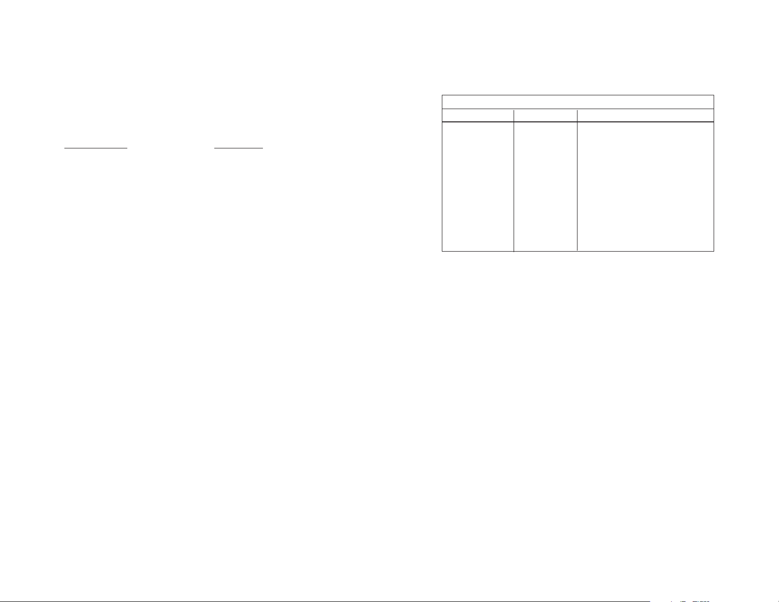
APPENDIX C
MODULAR INTERFACE PIN-OUTS
MODULAR INTERFACE - 10 Wire RJ-45 (EIA-561)
Contact Number Circuit Description
1 N/A Not Used
2 107 DSR
3 109 Received Line Signal Indicator (CD)
4 108 / 2 DTE Ready (DTR)
5 102 Signal Common
6 104 Received Data
7 103 Transmitted Data
8 106 Clear to Send
9 105 / 133 Request to Send / Ready for Receiving
10 N/A Not Used
Pins 2-9 conform to the EIA/TIA-561 eight position non-synchronous interface standard.
14
 Loading...