

Page 1
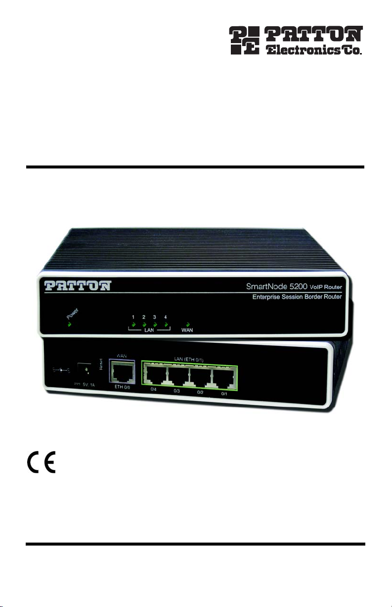
SmartNode™ Model 5200
Enterprise Session Border Router
Quick Start Guide
Important—This is a Class A device and is intended for use in a light industrial (commer-
cial) environment only. It is not intended nor approved for use in a heavy industrial or residential environment.
This device is approved for connection to the public ISDN telecommunication network, over BRI/S0ISDN interfaces.
Part Number: 07MSN5200-QS, Rev. A
Revised: April 21, 2010
Sales Office: +1 (301) 975-1000
Technical Support: +1 (301) 975-1007
E-mail: support@patton.com
WWW: www.patton.com
Page 2
WARNING
• Do not open the device when the power cord is connected. For systems without a power switch and without an external power
adapter, line voltages are present within the device when the power
cord is connected.
• For devices with an external power adapter, the power adapter shall
be a listed Limited Power Source The mains outlet that is utilized to
power the device shall be within 10 feet (3 meters) of the device,
shall be easily accessible, and protected by a circuit breaker in compliance with local regulatory requirements.
• For AC powered devices, ensure that the power cable used meets all
applicable standards for the country in which it is to be installed.
• For AC powered devices which have 3 conductor power plugs (L1, L2
& GND or Hot, Neutral & Safety/Protective Ground), the wall outlet
(or socket) must have an earth ground.
• For DC powered devices, ensure that the interconnecting cables are
rated for proper voltage, current, anticipated temperature, flammability, and mechanical serviceability.
• WAN, LAN & PSTN ports (connections) may have hazardous voltages
present regardless of whether the device is powered ON or OFF.
PSTN relates to interfaces such as telephone lines, FXS, FXO, DSL,
xDSL, T1, E1, ISDN, Voice, etc. These are known as “hazardous network voltages” and to avoid electric shock use caution when working
near these ports. When disconnecting cables for these ports, detach
the far end connection first.
• Do not work on the device or connect or disconnect cables during periods of lightning activity.
This device contains no user serviceable parts. This device can only be
repaired by qualified service personnel.
WARNING
This device is NOT intended nor approved for connection to the PSTN. It
is intended only for connection to customer premise equipment.
WARNING
2 SmartNode 5200 Quick Start Guide
Page 3
Electrostatic Discharge (ESD) can damage equipment and impair electrical
circuitry. It occurs when electronic printed circuit cards are improperly
handled and can result in complete or intermittent failures. Do the follow-
CAUTION
ing to prevent ESD:
• Always follow ESD prevention procedures when removing and replacing cards.
• Wear an ESD-preventive wrist strap, ensuring that it makes good
skin contact. Connect the clip to an unpainted surface of the chassis
frame to safely channel unwanted ESD voltages to ground.
• To properly guard against ESD damage and shocks, the wrist strap
and cord must operate effectively. If no wrist strap is available,
ground yourself by touching the metal part of the chassis.
1.0 Power up the SmartNode
The interconnecting cables shall be acceptable for external use and shall be rated for
the proper application with respect to voltage, current, anticipated temperature, flammability, and mechanical serviceability.
CAUTION
1. Connect the SmartNode to a power source using the included power supply and cable.
2. When the Power LED stops blinking and remains lit, the SmartNode is ready to configure.
2.0 Set your PC to DHCP
The interconnecting cables shall be acceptable for external use and shall be rated for
the proper application with respect to voltage, current, anticipated temperature, flammability, and mechanical serviceability.
CAUTION
This guide will allow you to quickly access the configuration interface of a SmartNode and give an overview of
the different elements you can or need to configure. For detailed information on all configuration parameters
refer to the SmartWare software configuration guide.
The SmartNode has a built in DHCP Server which allows an automatic IP connection with a connected PC. To prepare the connection you need to configure the PC to use DHCP. The following paragraphs show how to do this on
Windows. For other operating systems refer to the operating instructions of the PC.
SmartNode 5200 Quick Start Guide 3
Page 4
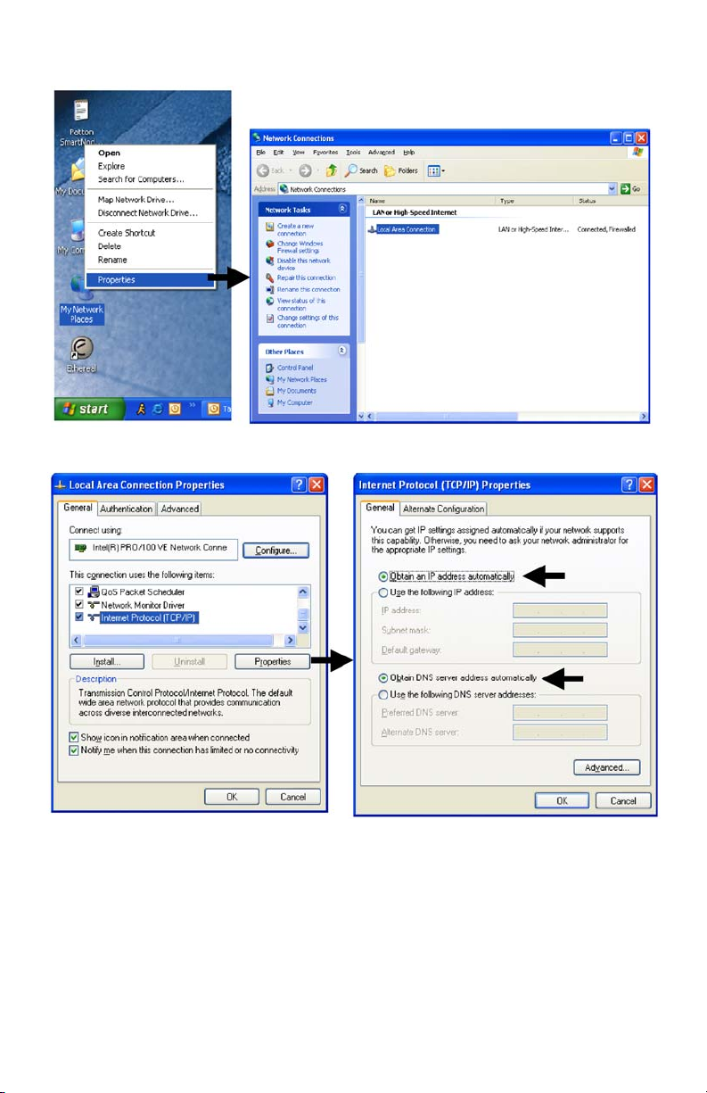
1. Right-click on My Network Places and select Properties in the context menu (see figure 1).
Figure 1. Displaying the Network Connections window
Figure 2. Displaying the Internet Properties (TCP/IP) Properties window
2. Double-click on Local Area Connection and click on Properties to open the Internet Protocol (TCP/IP)
Properties window (see figure 2).
3. Select Obtain an IP address automatically and Obtain DNS server address automatically options.
4. Click OK to save changes and close the properties windows.
4 SmartNode 5200 Quick Start Guide
Page 5

3.0 Connecting the SmartNode to your laptop PC
First the SmartNode must be connected to the mains power supply with the power cable. Wait until the Power
LED stops blinking and stays lit constantly. Now the SmartNode is ready.
The interconnecting cables shall be acceptable for external use and shall be rated for the proper application with respect to voltage, current, anticipated temperature, flammability, and mechanical serviceability.
CAUTION
The SmartNode 5200 Series is equipped with Auto-MDX Ethernet ports, so you can use straight-through cables
for host or hub/switch connections (see figure 3).
Straight-through wired cable
Laptop PC
Figure 3. Connecting the SmartNode to your laptop PC
The SmartNode comes with a built-in DHCP server to simplify configuration. Therefore, to automatically configure the PC for IP connectivity to the SmartNode, the laptop PC must be configured for DHCP. The SmartNode will
provide the PC with an IP address. You can check the connection to the SmartNode by executing the ping command from the PC command window as follows:
ping 192.168.1.1
LAN (ETH 0/1)
SmartNode 5200 Quick Start Guide 5
Page 6

4.0 Configuring the desired IP address
4.1 Factory-default IP settings
The factory default configuration for the Ethernet interface IP addresses and network masks are listed in the table
below. Both Ethernet interfaces are activated upon power-up. LAN interface ETH 0/1 (LAN) provides a default
DHCP server, the WAN interface uses DHCP client to automatically assign the IP address and network mask.
IP Address Network Mask
WAN interface Ethernet 0 (ETH 0/0) DHCP DHCP
LAN interface Ethernet 1 (ETH 0/1) 192.168.1.1 255.255.255.0
DHCP address range 192.168.1.10–192.168.1.19 255.255.255.0
If these addresses match with those of your network, go to section 5.0 “Connecting the SmartNode to the
network” on page 7. Otherwise, refer to the following sections to change the addresses and network masks.
4.2 Login
To access the SmartNode, start the Telnet application. Type the default IP address for the router into the address
field: 192.168.1.1. Accessing your SmartNode via a Telnet session displays the login screen. Type the factory
default login: administrator and leave the password empty. Press the Enter key after the password prompt.
login:administrator
password: <Enter>
192.168.1.1>
After you have successfully logged in you are in the operator execution mode, indicated by > as command line
prompt. With the commands enable and configure you enter the configuration mode.
192.168.1.1>enable
192.168.1.1#configure
192.168.1.1(cfg)#
4.3 Changing the WAN IP address
Select the context IP mode to configure an IP interface.
192.168.1.1(cfg)#context ip router
192.168.1.1(ctx-ip)[router]#
Now you can set your IP address and network mask for the interface ETH 0/0 (WAN). Within this example a network 172.16.1.0/24 address is assumed. The IP address in this example is set to 172.16.1.99 (you should set
this the IP address given to you by your network provider).
192.168.1.1(ctx-ip)[router]#interface eth0
192.168.1.1(if-ip)[eth0]#ipaddress 172.16.1.99 255.255.255.0
2002-10-29T00:09:40 : LOGINFO : Link down on interface eth0.
2002-10-29T00:09:40 : LOGINFO : Link up on interface eth0.
172.16.1.99(if-ip)[eth0]#
6 SmartNode 5200 Quick Start Guide
Page 7

Copy this modified configuration to your new start-up configuration. This will store your changes in non-volatile
memory. Upon the next start-up the system will initialize itself using the modified configuration.
172.16.1.99(if-ip)[eth0]#copy running-config startup-config
172.16.1.99(if-ip)[eth0]#
The SmartNode can now be connected to your network.
5.0 Connecting the SmartNode to the network
In general, the SmartNode will connect to the network via the WAN (ETH 0/0) port. This enables the SmartNode
to offer routing services to the PC hosts on LAN (ETH 0/1) port. The SmartNode 5200 Series is equipped with
Auto-MDX Ethernet ports, so you can use straight-through or crossover cables for host or hub/switch connections
(see figure 4).
The interconnecting cables shall be acceptable for external use and shall be rated for the proper application with respect to voltage, current, anticipated temperature, flammability, and mechanical serviceability.
CAUTION
LAN
Network
Straight-through wired or crossover cable
WAN (ETH 0/0)
LAN (ETH 0/1)
Figure 4. Connecting the SmartNode to the network
You can check the connection with the ping command from the SmartNode to another host on the network.
172.16.1.99(if-ip)[eth0]#ping <IP Address of the host>
Note If the WAN address is not set to DHCP, to ping a device outside your local LAN you must first configure
the default gateway. (For information on configuring the default gateway, refer to section “Set IP
addresses” in Appendix C, “Command Summary” of the SmartNode Series SmartWare Software Config-
uration Guide.)
SmartNode 5200 Quick Start Guide 7
Page 8

6.0 Loading the configuration (optional)
Patton provides a collection of configuration templates on the CD-ROM that came with the SmartNode device—
and also on the support page at www.patton.com/voip—one of which may be similar enough to your
application that you can use it to speed up configuring the SmartNode. Simply download the configuration note
that matches your application to your PC. Adapt the configuration as described in the configuration note to your
network (remember to modify the IP address) and copy the modified configuration to a TFTP server. The SmartNode can now load its configuration from this server.
Note Patton regularly adds new configuration templates to the collection at www.patton.com/voip, so if
you do not see your application on the CD-ROM, it may have been added to the website.
Note If your application is unique and not covered by any of Patton’s configuration templates, you can man-
ually configure the SmartNode instead of loading a configuration file template. In that case, refer to the
SmartNode Series SmartWare Software Configuration Guide for information on configuring the SmartNode device.
In this example we assume the TFTP server on the host with the IP address 172.16.1.11 and the configuration
named SN.cfg in the root directory of the TFTP server.
172.16.1.99(if-ip)[eth0]#copy tftp://172.16.1.11/SN.cfg startup-
config
Download...100%
172.16.1.99(if-ip)[eth0]#
After the SmartNode has been rebooted the new startup configuration will be activated.
When you issue the reload command, the SmartNode will ask if you want to copy the running configuration to the startup configuration. Since you just downloaded a configuration file to the startup configuration you must answer this question with NO. Otherwise, the downloaded configuration will be
IMPORTANT
overwritten and lost!
172.16.1.99(if-ip)[eth0]#reload
Running configuration has been changed.
Do you want to copy the 'running-config' to the 'startup-config'?
Press 'yes' to store, 'no' to drop changes : no
Press 'yes' to restart, 'no' to cancel : yes
The system is going down
7.0 Additional information
For detailed information about configuring and operating guidance, set up procedures, and troubleshooting,
refer to the SN5200 Getting Started Guide and SmartNode Series SmartWare Software Configuration Guide on
the CD-ROM.
8 SmartNode 5200 Quick Start Guide
Page 9

A.0 Customer and Technical Support
If you contact Patton support, you should have some system information ready to help us better help you. This
information allows us to quickly identify what product you are using and how it is configured. Therefore, we integrated a “system report” page that collects all relevant information and presents it to you on one web page.
Click on “Support” to access this page – the page also gives you instructions on where to send the report.
Toll-Free VoIP support: call sip:support@patton.com with a VoIP SIP client
Online support: www.patton.com
E-mail support: support@patton.com—answered within 1 business day
Telephone support:
•
Standard: +1 (301) 975-1007 (USA), Monday–Friday: 8:00 am to 5:00 pm EST (1300 to
2200 UTC/GMT)
•
Alternate: +41 (0)31 985 25 55 (Switzerland), Monday–Friday: 8:00 am to 5:00 pm CET (0900 to 1800
UTC/GMT)
Fax: +1 (253) 663-5693 (USA) or +41 (0)31 985 25 26 (Switzerland)
A.0 Appendix—Factory default IP addresses
Factory default IP addresses and netmask configuration.
IP Address Network mask
WAN interface Ethernet 0 (0/0) DHCP Client n/a
LAN interface Ethernet 1 (0/1) 192.168.1.1 255.255.255.0
DHCP server address range (LAN) 192.168.1.10-192.168.1.19 255.255.255.0
SmartNode 5200 Quick Start Guide 9
Page 10

B.0 Compliance Information
B.1 Compliance
EMC Compliance:
•
EN55022, Class A
•
EN55024
Low-Voltage Directive (Safety Compliance):
•
IEC/EN60950-1, 2nd edition
•
AS/NZS60950-1
PSTN:
•
TBR3:1995 A1
•
AS/ACIF SO31:2001
B.2 CE Declaration of Conformity
This device conforms to the requirements of Council Directive 1999/5/EC on the approximation of the laws of
the member states relating to Radio and Telecommunication Terminal Equipment and the mutual recognition of
their conformity.
The safety advice in the documentation accompanying this device shall be obeyed. The conformity to the above
directive is indicated by CE mark on the device.
B.3 Authorized European Representative
D R M Green
European Compliance Services Limited.
Avalon House, Marcham Road
Abingdon,
Oxon OX14 1UD, UK
10 SmartNode 5200 Quick Start Guide
Page 11

Copyright statement
Copyright © 2010, Patton Electronics Company. All rights reserved.
The information in this document is subject to change without notice. Patton Electronics assumes no
liability for errors that may appear in this document.
Trademarks statement
The term SmartNode is a trademark of Patton Electronics Company. All other trademarks presented in this document are the property of their respective owners.
Warranty, Trademark, & Compliance Information
For warranty, trademark and compliance information, refer to the SmartNode 5200 Getting Started Guide located
on the CD-ROM shipped with your SmartNode device or available online at www.patton.com.
In accordance with the requirements of council directive 2002/96/EC on Waste of
Electrical and Electronic Equipment (WEEE), ensure that at end-of-life you separate
this product from other waste and scrap and deliver to the WEEE collection system in
your country for recycling.
SmartNode 5200 Quick Start Guide 11
Page 12

NOTES
____________________________________________________________________
____________________________________________________________________
____________________________________________________________________
____________________________________________________________________
____________________________________________________________________
____________________________________________________________________
____________________________________________________________________
____________________________________________________________________
____________________________________________________________________
____________________________________________________________________
____________________________________________________________________
____________________________________________________________________
____________________________________________________________________
____________________________________________________________________
____________________________________________________________________
____________________________________________________________________
12 SmartNode 5200 Quick Start Guide
 Loading...