

Page 1
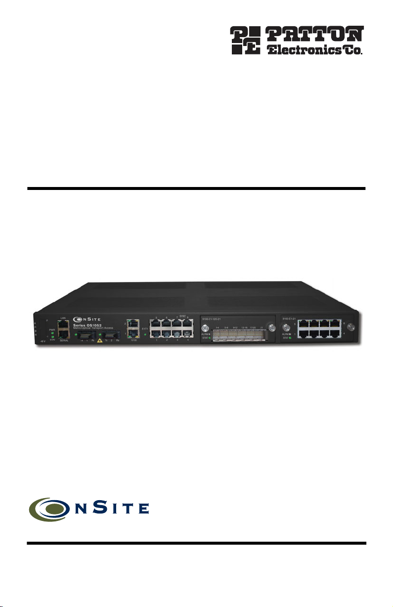
OnSite 1052 & 1063 Series
Metro-Optical Transport Access
Nodes
Quick Start Guide
Part Number: 07MOS10xx-QS, Rev. A
Revised: November 19, 2009
Sales Office: +1 (301) 975-1000
Technical Support: +1 (301) 975-1007
E-mail: support@patton.com
WWW: www.patton.com
Page 2
WARNING
Read the safety information in the OnSite Series
and
Administrator’s Reference Guide
operating your OS-10 Series system. Failure to follow this safety information can lead to personal injury or damage to the equipment.
thoroughly before installing and
Getting Started Guide
1.0 Unpacking and Installation
1.
Check the contents of the shipping container and accessories box or bag against the content list and the
packing slip. Verify that you received all listed equipment and inspect all items for shipping damage.
2.
Unpack the OS-10 Series chassis and install it into a rack according to the instructions in the
Getting Started Guide
3.
Verify that the site where you wish to install and operate the equipment conforms to the environmental
requirements in the
on the CD-ROM shipped with your unit.
OnSite Series Getting Started Guide
.
2.0 Powering Up the System
If your OS-10 Series system was ordered for use with AC power, follow these steps:
For your safety and to avoid damage to the equipment, follow the precautions, instructions and wiring procedures in the OnSite Series
WARNING
Started Guide
power source.
before connecting the OS-10 Series system to an AC or DC
OnSite Series
Getting
1.
Connect the enclosed AC power cable to the AC power receptacle on the rear side of the OS-10 Series
chassis.
2.
Connect the power cable plug to an AC power source with the following characteristics: 15 A at 120 VAC
(60 Hz) or 10 A at 240 VAC (50 Hz) circuit with overcurrent protection.
Refer to the OS-10 Series Installation and Operation Guide if your system was ordered for use with DC power (–
48 VDC nominal).
When you first apply power to the system, the STAT (status) LED on the front panel becomes a solid amber light.
This light indicates that the system is booting. The STAT LED becomes a solid green light when the system completes the boot process and is ready for management access and operation.
2
OnSite Series Quick Start Guide
Page 3

3.0 Accessing and Configuring the System
To access the system management functions for the first time, your may use either the SERIAL or the Ethernet
LAN management port. Refer to the Installation and Operation Guide for access through the SERIAL port.
For first time access through the Ethernet LAN management port, follow these steps:
1.
Connect a PC to the Ethernet LAN management port using the RJ-45 connector.
2.
Configure the PC to connect to the OS-10 Series system using the factory default settings for the Ethernet
LAN management port.
Note
By default, the IP address is set to 192.168.2.100.
3.
Launch the Web browser of your choice, and type the default IP address of the system in the Address field
of the browser.
4.
Log in to the OS-10 Series system using the super user ID and password.
Note
The factory-assigned default password for the Super user is super (all lowercase letters).
Once you gain access to the system using the default settings, change the IP settings for the LAN port for secure
access to the system.
3.1 Changing the IP Settings for the LAN port
To configure the Ethernet LAN management port settings, follow these steps:
1.
Select the SYSTEM folder from the OnSight Device Manager (DM) web-based GUI navigation menu.
2.
From the expanded SYSTEM folder, select Management Access, and from this folder select LAN.
3.
On the Ethernet LAN Management Port page, type the new LAN IP Address.
Note
The Admin Status for the Ethernet LAN management port is always enabled.
4.
Click on Apply.
The new IP settings take effect once you click on the Apply button. This change in settings causes the loss of
access connectivity to the system. You can regain access immediately by typing the new IP address of the LAN
port in the Address field of the browser. (Make sure that you change your PC settings to allow connectivity to the
OS-10 Series system over the same IP subnetwork.)
You will need to save the system configuration to avoid losing the new IP settings after a subsequent reboot.
Note
The system uses the last saved configuration to restore system operation and traffic connectivity after
the completion of the reboot. Any recent configuration data and connections not saved to the system
configuration file are lost and need re-entry, if required.
OnSite Series Quick Start Guide
3
Page 4

3.2 Saving the System Configuration
To save the system configuration to the flash memory, follow these steps:
1.
Select the SYSTEM folder from the OnSight DM web-based GUI navigation menu.
2.
From the expanded SYSTEM folder, select the Actions folder.
3.
From the expanded Actions folder, select Save Configuration.
A warning window opens to alert you to the start of the save-configuration process. Click on OK to continue or
Cancel to cancel the request.
4.0 Additional Information
The system is now ready for operation using the OnSight DM web-based graphical user interface (GUI). You may
now configure the system clock, timing mode and STM-1 interface settings for your intended application.
Refer to the
CD-ROM shipped with your device
OnSite Series Getting Started Guide
.
and the
OnSite Series Administrator’s Reference Guide
located on the
A.0 Customer and Technical Support
Online support: www
E-mail support:
.patton.com
support@patton.com
—answered within 1 business day
Telephone support:
Standard: +1 (301) 975-1007 (USA), Monday–Friday: 8:00 am to 5:00 pm EST (1300 to
•
2200 UTC/GMT)
•
Alternate: +41 (0)31 985 25 55 (Switzerland), Monday–Friday: 8:00 am to 5:00 pm CET (0900 to 1800
UTC/GMT)
Fax:
+1 (253) 663-5693
(USA)
or +41 (0)31 985 25 26 (
Switzerland)
Copyright statement
Copyright © 2009, Patton Electronics Company. All rights reserved.
The information in this document is subject to change without notice. Patton Electronics assumes no
liability for errors that may appear in this document.
In accordance with the requirements of council directive 2002/96/EC on Waste of
Electrical and Electronic Equipment (WEEE), ensure that at end-of-life you separate
this product from other waste and scrap and deliver to the WEEE collection system in
your country for recycling.
4
OnSite Series Quick Start Guide
 Loading...