

Patterson WWP30E-5-10-208-G-L/R Operation Manual

DOC #
A0000466 / A0000467 Rev1
Patterson Company
870 Riversea Road
Pittsburgh, PA 15233
Phone: 800-322-2018
FAX: 412-322-2785
OPERATIONS/PARTS MANUAL
FOR
PATTERSON'S
WWP30E-5-10-208-G-L/R
ELECTRIC WINCH.
Please fi ll in the following blanks and then keep this manual in a safe and convenient location. When calling with either questions or replacement part needs, always refer to the Winch
Model, Part Number and Serial Number.
WINCH PART #: A0000466/A0000467 WINCH SERIAL #: _____________
MOTOR MFG.: _____________________ MOTOR SERIAL #: __________________
BRAKE SERIAL #: _________________ DATE PURCHASED: ________________
DISTRIBUTOR INFORMATION
NAME: _________________________________________________________________
ADDRESS: ______________________________________________________________
CITY: _____________________________ STATE: ___________ ZIP: ____________
PHONE: ___________________________ FAX: _____________________________

IMPORTANT!
Prior to installing and operating the winch, please read this manual thoroughly
and carefully. Keep this manual and all other instructions accessible at all times.
Although this manual will help you become familiarized with the operating procedures for the winch, it is by no means a substitute for proper training and the
safe use of winches, barge rigging and other marine equipment. Because owners and operators are solely responsible for determining whether a particular
usage is acceptable, only individuals trained in the proper use of winches, barge
rigging and other marine equipment should operate winches.
The typical operational environment of winches includes very high forces, and
the potential hazards associated with these forces should not be underestimated.
Improper installation or misuse of the winch may result in injury to persons or
cause equipment failure or damage.
ALWAYS OBSERVE THESE BASIC SAFETY PRE-
CAUTIONS:
• To reduce potential of electrical shock or other injury, turn off and lock out or tag
out power source before initiating any maintenance or repairs.
• Keep all fi ngers, loose clothing and any foreign objects away from winch while in
operation.
• During operation of the winch, always remain to the side of the winch, slightly behind the gear motor.
• Never operate the winch from the front or when bystanders are in front of it.
• Operators and bystanders should stay clear of any load and the wire rope while the
winch is operating.
• Under no circumstances, should any winch be used to move, raise or lower a
person(s) or equipment.
• Do not operate the winch unless you have a fi rm stance on a non-slippery surface.
• Do not apply tension to the winch unless there are at least four complete wraps of
rope on the drum.
• Inspect the winch carefully at least once a month for worn gears and pawls, cracked
welds, and other damaged parts. If any worn, cracked or damaged parts are found,
stop use immediately and remove the winch from service until all appropriate repairs
are completely made.
1. INSTALLATION
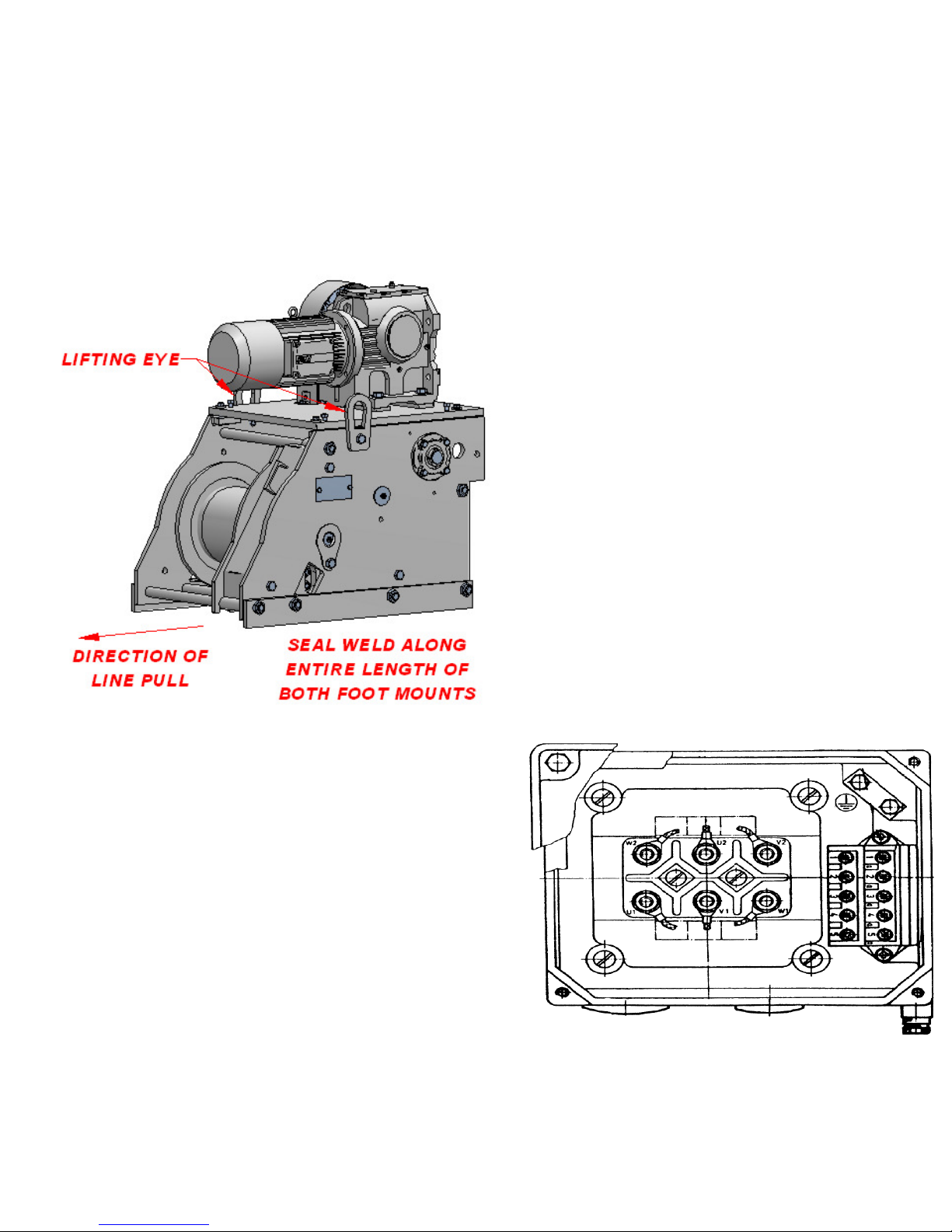
WINCHES SHOULD ONLY BE LIFTED BY THE
LIFTING EYES ON EACH SIDE OF THE WINCH.
NEVER LIFT THE WINCH BY THE GEARMOTOR
OR DAMAGE WILL OCCUR !
WARNING! ONLY A QUALIFIED ELECTRICIAN SHOULD
WIRE CONTROL BOX AND REMOTE STATION OF A
WINCH. W. W. PATTERSON COMPANY IS NOT LIABLE
FOR DAMAGE CAUSED BY UNAUTHORIZED OR UNQUALIFIED PERSONNEL ATTEMPING TO CONNECT
A WINCH TO A POWER SOURCE.
1.4. All winches have been factory wired to the voltage
specifi ed at the time of original purchase. All winches have
been factory tested prior to shipment to insure proper
operation. Assuming the control box and remote station
have been properly installed and wired, no further wiring
is required except to connect the winch to the control box.
1.5. Open the conduit box located on the motor. The
conduit box has been confi gured to the voltage specifi ed
at the time of original purchase.
1.1. All winches must be installed on fl at, rigid and non-
slippery surfaces. Deck and structure must be strong
enough to withstand the weight and holding capacity of
the winch, and the forces likely to occur during operation.
1.2. Place the winch in the mounting area, in line with the
direction of cable pull. Check to make sure there is enough
clearance and Fleet Angle Distance for proper operation.
(Refer to Diagram on Page 8.)
WARNING! EACH WINCH HAS BEEN FACTORY WIRED
TO THE VOLTAGE SPECIFIED AT THE TIME OF ORIGINAL PURCHASE.
1.3. Weld to deck along the complete length of both foot
mounts. Use seal welding to protect the weld against corrosion. Remember, the weld has to be strong enough to
withstand loads equal to, at least, the Ultimate Shock Load
Capacity of the winch.
3

1. INSTALLATION (Cont'd.)
4
1. INSTALLATION (Cont'd.)
1.6. Connect each of the three wires from the control box
to one of the three usable groups of wires in the conduit
box. Please review the label inside the conduit box for the
specifi c wiring schematic. Properly close the cover on the
conduit box.
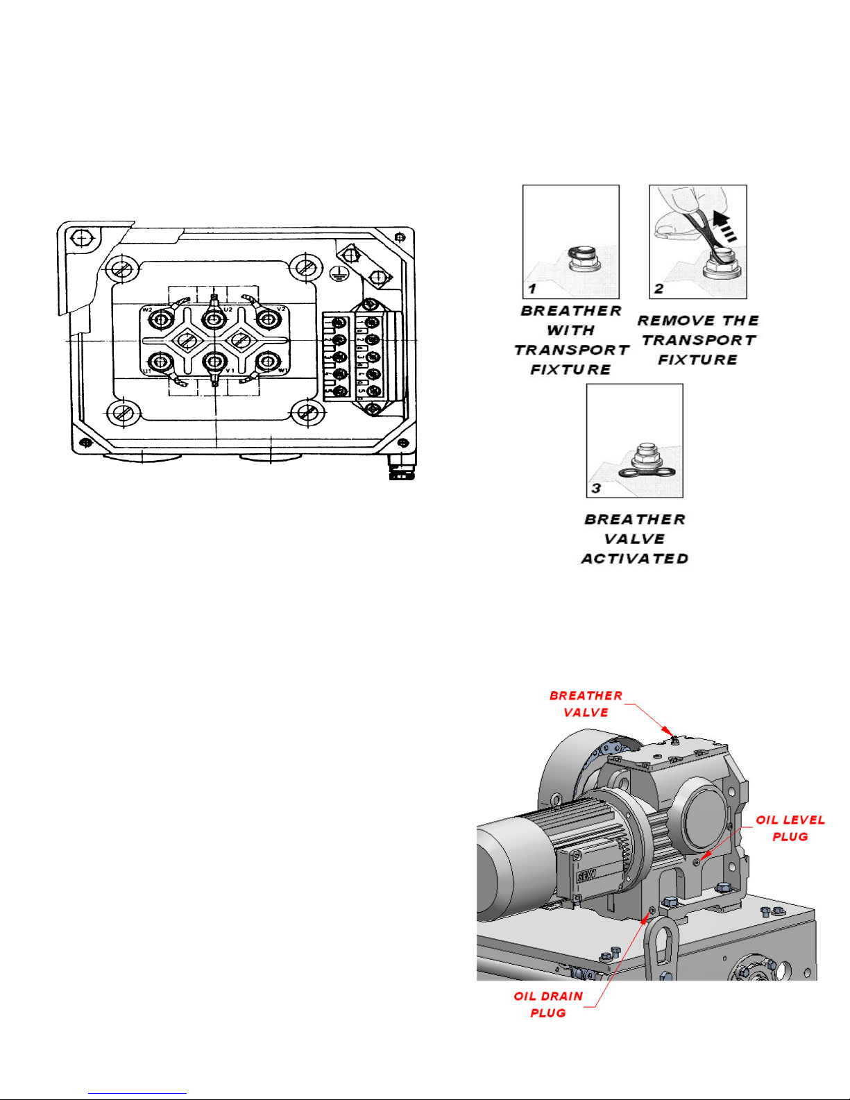
WARNING! FAILURE TO REMOVEL THE BREATHER
VALVE TRANSPORT FIXTURE MAY RESULT IN DAMAGE
TO THE GEARBOX.
WARNING! ONLY A QUALIFIED ELECTRICIAN SHOULD
PERFORM THIS WIRING. CAUTION MUST BE TAKEN
TO CAREFULLY READ AND UNDERSTAND THE WIRING SCHEMATIC FOUND ON THE INSIDE OF THE
COVER OF THE CONDUIT BOX.
1.7. Disengage the locking dog. Depressing either the
IN or OUT button on either the control box or the remote
station, test to make sure the winch drum turns in the appropriate direction; the rope must reel in from the bot-
tom of the winch drum. Should the winch drum turn in
the opposite direction than desired, open the conduit box
and disconnect two of the wires leading from the control
box. Reverse the position of those two wires in respect to
their original position. Reconnect each of the two wires to
each of the bundle of wires from the winch motor. Close
the conduit box. The winch drum should now turn in the
proper direction.
WARNING! TO REDUCE POTENTIAL OF ELECTRICAL
SHOCK OR OTHER INJURY, TURN OFF AND LOCK OUT
OR TAG OUT POWER SOURCE BEFORE INITIATING
ANY MAINTENANCE OR REPAIRS.
1.8. Coat all gear teeth with heavy-duty gear grease and
lubricate both sprockets and the roller chain.
1.9.Remove the Breather Valve Transport Fixture Shipping Plug
and discard properly. The gearbox must be checked to insure
the gearbox is fi lled to the proper level with oil. When touching
up paint on winches, DO NOT paint over the Breather Valve.
5
 Loading...