

Patterson HIGH-5 Installation Manual
HIGH-5
High Volume Ceiling Fan
Installation Manual
Blythewood, SC 29016 · 800.768.3985 · www.pattersonfan.com

Addendum
To
High-5
Installation
Instructions
(Mechanical Only)
Please Note: This document is meant to be used in conjunction with
the Installation Instruction drawings that accompany this unit.
Rev 3, Page 4

INCLUDED IN YOUR SHIPMENT
5 Fan Blades
1 Fan Assembly
1 Mounting Bracket
4 Turnbuckles ¼”
Bolts, nuts, washers, and clamps of various sizes (see High-5 Installation Instruction drawings
for types and quantities)
FAN SAFETY COMPONENTS PROVIDED
Assembly safety cable (1)
Guy wires (4)
Blade Safety plates (5)
Blade/Hub safety wire (1)
TOOLS TO GET STARTED
Scissor lift
Wrench and socket set (5/16” – ¾” needed)
¼” Nut driver
Torque wrench
Standard and Phillips screwdrivers
Level
Note: In order to protect personnel, equipment, and the fan, it is important that all of the
above safety components are installed per these instructions. Failure to properly install any or
all of these safeguards may void the manufacturer’s warranty.
FAN SPACING, PLACEMENT, AND CLEARANCE
Fans should be mounted such that the blades are a minimum of 10 feet above the floor. Also,
ensure that the fan blades have a clearance equal to 15% of the fan’s diameter in all directions.
Care should be taken when installing the fan around a fire sprinkler system. The VFD is
equipped with the ability to connect to the fire suppression system – emergency stopping the
fans in case of a fire. However, it is the responsibility of the installer to read and comply with
all local codes and regulations.
MAINTENANCE
Prior to performing any maintenance on the fan, it MUST be disconnected from the power
source by means of the lockable disconnect located on the VFD box.
Control Boxes – Clean inside of boxes occasionally, gently using a can of compressed air if
desired. Wipe down or dust the exterior of the boxes periodically
Rev 3, Page 5

Gearbox – Periodic maintenance will ensure your fan remains operational for its intended life.
While Patterson recommends that the end-user annually checks and changes the gearbox oil,
failure to do so will not void any warranties. Oil type used is Chevron® Delo Gear ESI 85W-140.
Contact Patterson at (800) 768-3985 for availability.
Hub Grease – Hub should be inspected yearly to ensure proper lubrication. Grease type is
Mobil Unirex EP2. Add grease as needed, filling slowly until grease passes through the upper
seal hole.
Mounting Hardware – All nuts and bolts related to mounting of the fan unit should be checked
for tightness annually. In addition, guy wires need to be inspected to ensure they remain taut
and show no signs of fraying.
Blades – Blades can be occasionally wiped down with a damp cloth. A mild detergent can also
be used if desired. Inspect safety devices yearly; ensure that safety plate bolts are tightened as
recommended and that safety cable remains in place.
Rev 3, Page 6

INSTALLATION PROCEDURES – KEY POINTS
Step 1: Install Mounting Hardware
- Reference: Page 11 and Page 16 of the High-5 Installation Instructions
A) It is important to attach the mounting hardware separately from the fan assembly.
B) Attach the mounting hardware as shown on page 11 of the Installation Instructions.
i) Refer to the diagram on page 11 to determine which set of bolt slots to
use on the mounting hardware. For I-beam width less than 7¼”, use slots
labeled “A”. I-beams wider than 7¼” should use slots labeled “B”.
ii) For I-beam thickness greater than ½”, use the provided spacer as shown
in Note 3, page 11.
iii) Be sure to tighten all nylon lock nuts to appropriate torque to prevent
them from vibrating loose during operation. Nuts can be used only once.
iv) If a downrod was ordered, attach one end of the rod to the swivel joint
on the mounting hardware using the downrod clamp (see page 11 of the
Installation Instructions).
Step 2: Attach Fan Assembly to Mounting Hardware
- Reference: Page 12, View A of the High-5 Installation Instructions
A) Using a scissor lift, raise the fan assembly until its mounting holes line up with the holes
on the swivel joint at the bottom of the mounting hardware (see page 12, view A). If a
downrod is used, attach the fan assembly to the holes provided on the end of the rod.
B) Important: Please note that the swivel joint (or downrod) must be located in between
the mounting holes on the fan assembly. Refer to page 12, View A.
C) Secure the fan assembly to the mounting hardware (or end of the downrod) as shown
on page 12 view A of the Installation Instructions.
Step 3: Install Fan Assembly Safety Cable
- Reference: Page 12, View A of the High-5 Installation Instructions
Note: This step is mandatory. Failure to install the safety cable may void the manufacturer’s
warranty.
A) Pass one end of the safety cable through the holes on the assembly’s vertical supports
(see page 12, view A).
Rev 3, Page 7
B) The opposite end of the safety cable should be passed over the top of the I-beam.
C) Connect the two ends of the cable together by means of 4 saddle clamps (provided) in
the manner shown on page 12, view A of the Installation Instructions. Tighten the
saddle clamps securely using a ½” socket.
Step 4: Install Guy Wires
- References: Page 12 and Page 17 of the High-5 Installation Instructions
Note: For maximum stability, the angle formed between the guy wire and the ceiling should be
less than 45 degrees.
This step is mandatory. Failure to install the guy wires may void the manufacturer’s
warranty. The following steps should be performed with the aid of a scissor lift.
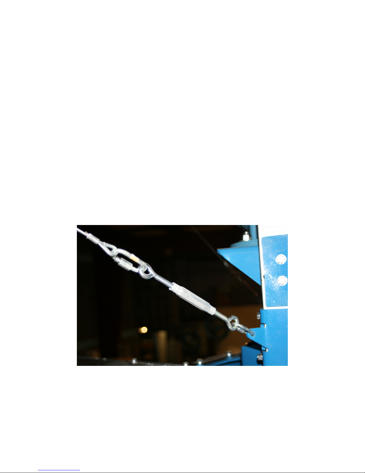
A) Open the quick link located on the fan assembly. Slide one eye of the 1/4” turnbuckle
into the link. Close the quick link.
B) On the opposite eye of the turnbuckle, attach another quick link, followed by the looped
end of the guy wire. It should appear like the picture below. Also see: page 12, View B.
C) Pass the opposite end of the guy wire through the eye bolt of a beam clamp (not
supplied). Pull the wire as tight as possible, making sure the fan assembly remains in
the vertical position. Use 3 saddle clamps to crimp the end of the guy wire together in
the manner shown on page 12, view D of the Installation Instructions.
Rev 3, Page 8
 Loading...