

Page 1 / 6
Important to Know:
1. If you are not familiar with state and local electrical
codes, it is recommended that you consult with a
qualified electrician.
2. This fixture requires a 120 VAC, 60 Hz power
source.
3. For general safety and to avoid any possible
damage to the sensor, be sure the power is
switched "off" before adjustment.
Maximum Wattage: 2-150 W (bulb included)
Working Temperature Range: - 40F ~ 1130F
ASSEMBLY AND INSTALLATION
INSTRUCTIONS
NOTES: 1. Before installing, consult local electrical codes for wiring and grounding requirements.
2. Customer Service: 1-800-887-6326 (weekdays 9 a.m. – 5 p.m. CST)
3. READ AND SAVE THESE INSTRUCTIONS.
356-9231 / 356-9232
150619
Features:
WARNING:
TO AVOID RISK OF ELECTRICAL SHOCK, BE SURE TO SHUT OFF
POWER BEFORE INSTALLING OR SERVICING THIS FIXTURE.
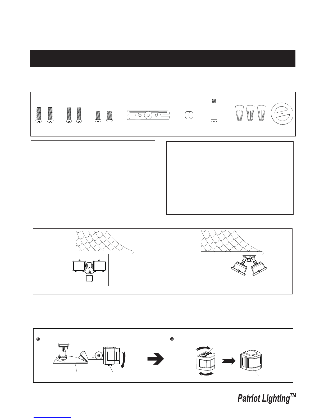
Note: Fixture can be wall mounted or eave mounted.
Wall Mounted
Eave Mounted
Read notes section on page 4 for additional information about mounting location of fixture.
Light fixture and sensor should be mounted as shown above when installed (depending upon type of installation)
Before installing the light fixture under an eave, the sensor head must be rotated as shown in the next two steps for
proper operation and to avoid the risk of electrical shock.
For eave mounted only:
Rotate the sensor head towards the back plate.
Rotate the sensor head clockwise 180˚ so the controls face down.
Controls
Back Plate
Controls
Controls
1. Motion sensor: turns light ON automatically when
motion is detected and turns light OFF automatically
when motion stops.
2. Photocell keeps the light OFF during daylight hours.
Hardware Package (included):
Decorative cover
Fixture Mounting Screw
Mounting Strap
Wire Nut X3
Gasket
Mounting Screw X2
#8/32X1/2 in
Mounting Screw X2
#6/32 X1/2 in
Mounting Screw X2
#10/24 X1/4 in
Installation Steps
Page 2 / 6
150619
Turn off the power at fuse or circuit box.
Turn on the power at fuse or circuit box.
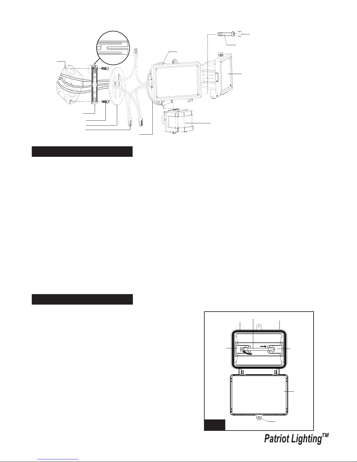
1. Install the mounting strap to the outlet box with the stamped word “FRONT” facing away from the outlet box, using
two mounting screws that best fit the outlet box. back plate should sit flush against wall surface when secured.
(Choose one matching pair of suitable mounting screws from the 3 pairs provided)
2. Fixture wires thread through gasket, then attach the gasket into back plate.
3. Pull out the source wires from the outlet box. Make wire connections using wire nuts as follows:
---Connect the black wire from the fixture to the “hot” wire from the power source. (usually black)
---Connect the white wire from the fixture to the neutral wire from the power source. (usually white)
---Connect the grounding wire from the fixture to the grounding wire from the power source. (usually green / yellow
insulation)
Carefully tuck the wires back into the outlet box.
4. Attach the back plate of the light fixture to the mounting strap, secure it with the fixture mounting screw.
5. Push the decorative cover firmly into the fixture mounting screw hole on the light.
6. With silicone caulking compound, caulk completely around where the back plate meets the wall surface.
CAUTION: Be sure to caulk completely where the back plate meets the wall surface to prevent water from
seeping into the outlet box.
Sensor
Mounting Strap
Outlet Box
Wire Nut
Back Plate
Mounting Screw
Fixture Mounting Screw
FRONT
Decorative cover
Gasket
T3 Halogen Bulb Max.150W
(included)
Light Head
Replacing Bulb Steps
Use a clean glove or cloth when handing the new blub. Use
isopropyl (rubbing) alcholol to clean the bulb if it is touched with
bare hands.
1. Using a phillips screwdriver (not included), loose the glass cover
locking screw on the light head and lower the glass cover.
2. To remove the bulb, push the bulb to the right until the left side
of the bulb is clear of the left bulb socket.
3. Place one end of the bulb on the contact in the right bulb socket.
While pushing the bulb agaist the contact, lower the other end of
the bulb onto the contact in the left bulb socket. The bulb should
spin easily if it is seated properly.
4.Before closing the glass cover, make sure the gasket is seated
properly in the groove around the edge of the light head. Close
the glass cover and tighten the locking screw securely.
Bulb
Gasket
Left Bulb
Socket
Right Bulb
Socket
Locking Screw
Glass
Cover
Light Head
Fig. 1
 Loading...